$ 0
0
$ 0
0

John Deere 310E Backhoe Loader Operation and Test Technical Manual (TM1648)

Format: PDF (Printable Document)

File Language: English
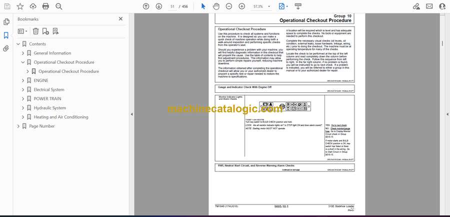
File Pages: 456

File Size: 9.58 MB (Speed Download Link)

Brand: John Deere

Model: 310E Backhoe Loader

Book No: TM1648

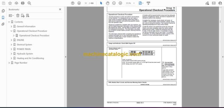
Type of Document: Operation and Test Technical Manual

Categories: ,

$ 40

Share:

John Deere 310E Backhoe Loader Operation and Test Technical Manual (TM1648)

John Deere 310E Backhoe Loader Operation and Test Technical Manual (TM1648)

📘 Show Index

John Deere 310E Backhoe Loader Index:

  • Contents
    • General Information
      • Safety Information
        • Handle Fluids Safely—Avoid Fires
        • Prevent Battery Explosions
        • Prepare for Emergencies
        • Prevent Acid Burns
        • Handle Chemical Products Safely
        • Avoid High-Pressure Fluids
        • Park Machine Safely
        • Support Machine Properly
        • Wear Protective Clothing
        • Work in Clean Area
        • Service Machines Safely
        • Work In Ventilated Area
        • Illuminate Work Area Safely
        • Replace Safety Signs
        • Use Proper Lifting Equipment
        • Remove Paint Before Welding or Heating
        • Avoid Heating Near Pressurized Fluid Lines
        • Keep ROPS Installed Properly
        • Service Tires Safely
        • Practice Safe Maintenance
        • Use Proper Tools
        • Decommissioning — Proper Recycling and Disposal of Fluids and Components
        • Live With Safety
      • General Specifications
        • 310E Backhoe Loader Dimensions
        • 310E Backhoe Loader Specifications
        • Other Information—310E Backhoe Loader
        • 310E Backhoe Loader Weight
        • 310E Buckets
        • 310E Backhoe Loader Drain and Refill Capacities
        • 310E Backhoe Loader Lifting Capacities—Standard Dipperstick
        • 310E Backhoe Loader Lifting Capacities—Extendible Dipperstick (Retracted)
        • 310E Backhoe Loader Lifting Capacities—Extendible Dipperstick (Extended)
      • Torque Values
        • Hardware Torque Specifications
        • ROPS Torque Specifications
        • Metric Bolt and Screw Torque Values
        • Additional Metric Cap Screw Torque Values
        • Unified Inch Bolt and Screw Torque Values
        • Check Oil Lines And Fittings
        • O-Ring Groove Connections
        • Service Recommendations for O-Ring Boss Fittings
        • Service Recommendations for Flat Face O-Ring Seal Fittings
        • Service Recommendations for Metric Series Four Bolt Flange Fitting
        • Service Recommendations For Inch Series Four Bolt Flange Fittings
      • Fuels and Lubricants
        • Diesel Fuel
        • Low Sulfur Diesel Fuel Conditioner
        • Diesel Fuel Storage
        • Do Not Use Galvanized Containers
        • Fuel Tank
        • Diesel Engine Oil — Non-Emissions Certified and Certified Tier 1 and Stage I
        • Diesel Engine Coolant (engine with wet sleeve cylinder liners)
        • Transmission, Axles and Mechanical Front Wheel Drive Oil
        • Hydraulic Oil
        • Grease
        • Grease for Extendible Dipperstick
        • Alternative and Synthetic Lubricants
        • Lubricant Storage
        • Mixing of Lubricants
    • Operational Checkout Procedure
      • Operational Checkout Procedure
        • Operational Checkout Procedure
          • Gauge and Indicator Check With Engine Off
          • FNR, Neutral Start Circuit, and Reverse Warning Alarm Checks
          • Park Brake, Seat Position Sensor, Tachometer/Hour Meter Circuit and Engine Speed Control Linkage Checks
          • Brake System Checks
          • Steering System Checks
          • Transmission Neutral Disconnect Circuit Check
          • Driving Checks
          • Ride Control Operational Checks (If Equipped)
          • Mechanical Front Wheel Drive (MFWD) Driving Check
          • Hydraulic System Checks
          • Check Operation of Accessories (Engine Stopped)
          • Cab Component Checks
          • Miscellaneous Checks
    • ENGINE
      • Theory of Operation
        • POWERTECHPOWERTECH is a trademark of Deere & Company® 4.5 L (4045) John Deere Engine—Use CTM104
        • Engine—Sectional View
        • General Engine Description
      • Diagnostic Information
        • POWERTECHPOWERTECH is a trademark of Deere & Company® 4.5 L (4045) John Deere Engine—Use CTM104
        • Make Visual Inspection of Engine and Supporting Systems
        • Diagnose Engine Malfunctions
      • Adjustments
        • POWERTECHPOWERTECH is a trademark of Deere & Company® 4.5 L (4045) John Deere Engine—Use CTM104
        • JT05801 Clamp-On Electronic Tachometer Installation
        • Adjust Speed Control Lever Tension
        • Engine Speed Control Linkage
        • Slow and Fast Idle
      • Tests
        • POWERTECHPOWERTECH is a trademark of Deere & Company® 4.5 L (4045) John Deere Engine—Use CTM104
        • JT05801 Clamp-On Electronic Tachometer Installation
        • JT05800 Digital Thermometer Installation
        • Air Intake System Leakage Test
        • Radiator Air Flow Test
        • Altitude Compensator Boost Pressure Engine Performance Test
        • Injection Pump Timing
        • Fuel Line Leakage Test
    • Electrical System
      • System Information
        • Visually Inspect Electrical System
        • Malfunctions
        • High Resistance Circuit
        • Open Circuit
        • Grounded Circuit
        • Shorted Circuit
        • Multimeter
        • Seven Step Electrical Test Procedure
        • System Functional Schematic Information
        • Reading a System Functional Schematic
        • Reading a Component Location Diagram
        • Electrical Schematic Symbols
      • System Diagrams
        • Component Identification Table
        • Fuse (Blade-Type) Color Codes
        • Fuse Specifications
        • Wiring and Schematic Diagrams Legend
        • System Functional Schematic Section Legend
        • System Functional Schematic
        • Cab Roof Harness (W5) Component Location
        • Cab Roof Harness (W5) Connectors, Wire, and Pin Location
        • Cab Side Console Harness (W6) Component Location
        • Cab Side Console Harness (W6) Connectors, Wire, and Pin Location
        • Front Console Harness (W7) Component Location
        • Front Console Harness (W7) Connectors, Wire, and Pin Location
        • Engine Harness (W8) Component Location
        • Engine Harness (W8) Connectors, Wire, and Pin Location
        • Blower Harness (W10) Component Location
        • Blower Harness (W10) Connectors, Wire, and Pin Location
        • Radio Harness (W12) Component Location
        • Radio Harness (W12) Connectors, Wire and Pin Location
        • Air Conditioning Compressor Harness (W11) Component Location
        • Air Conditioning Compressor Harness (W11) Connectors, Wire, and Pin Location
        • Auxiliary Flow Control Harness (W15) Component Location
        • Auxiliary Flow Control Harness (W15) Connectors, Wire, and Pin Location
        • Ride Control Harness (W17) Component Location
        • Ride Control Harness (W17) Connectors, Wire, and Pin Location
      • Sub-System Diagnostics
        • Power Circuit Operational Information
        • Power Circuit Theory of Operation
        • Power Circuit Schematic
        • Power Circuit Sub-System Diagnostics
          • Power Circuit Diagnostic Procedures
        • Start Circuit Operational Information
        • Start Circuit Theory of Operation
        • Start Circuit Schematic
        • Start Circuit Sub-System Diagnostics
          • Start Circuit Diagnostic Procedures
        • Charging Circuit Operational Information
        • Charging Circuit Theory of Operation
        • Charging Circuit Schematic
        • Charging Circuit Sub-System Diagnostics
          • Charging Circuit Diagnostic Procedures
        • Display Monitor Circuit Operational Information
        • Display Monitor Circuit Theory of Operation
        • Display Monitor Circuit Schematic
        • Display Monitor Sub-System Diagnostics
          • Display Monitor Diagnostic Procedures
        • Indicator Circuit Specifications
        • Indicator Circuit Operational Information
        • Indicator Circuit Theory of Operation
        • Indicator Circuit Schematic
        • Indicator Circuit Sub-System Diagnostics
          • Indicator Circuit Diagnostic Procedures
        • Park Brake/Neutral Disconnect Circuit Specifications
        • Park Brake/Neutral Disconnect Circuit Operational Information
        • Park Brake/Neutral Disconnect Circuit Theory of Operation
        • Park Brake/Neutral Disconnect Circuit Schematic
        • Park Brake/Neutral Disconnect Circuit Sub-System Diagnostics
          • Park Brake/Neutral Disconnect Circuit Diagnostic Procedures
        • Ride Control Circuit Operational Information
        • Ride Control Circuit Theory of Operation
        • Ride Control Circuit Schematic
        • Ride Control Circuit Sub-System Diagnostics
          • Ride Control Circuit Diagnostic Procedures
      • References
        • Alternators and Starting Motors—Use CTM77
        • JT05801 Clamp-On Electronic Tachometer Installation
        • Battery Operation
        • Battery Specifications
        • Diagnose Battery Malfunctions
        • Check Battery Electrolyte Level and Terminals
        • Using Booster Batteries—12 Volt System
        • Alternator Operation—65 Amp and 95 Amp Bosch
        • Alternator Operation—65 Amp and 95 Amp Bosch—Continued
        • Tachometer Calibration (Serial No. —852337)
        • Tachometer Calibration (Serial No. 852338— )
    • POWER TRAIN
      • Theory of Operation
        • Standard Differential MFWD Operation
        • Power Train Overview
        • Torque Converter Operation
        • Clutch Pack, Forward or Reverse Operation
        • Synchronizer Operation
        • Transmission Pump Operation
        • Transmission Filter Operation
        • Manual Shift Transmission Operation—First Gear Forward
        • Manual Shift Transmission Operation—Third Gear Reverse
        • Mechanical Front Wheel Drive (MFWD) Operation
        • Transmission Control Valve Operation
        • Transmission Control Circuit—Neutral With Park Brake Off
        • Transmission Control Circuit—Forward
        • Transmission Control Circuit—Reverse
        • Modulation Valve Operation
        • Differential Operation
        • Differential Lock Operation
        • Brake Valve Operation
        • Service Brake Operation
        • Park Brake Operation
        • MFWD Differential Operation—Unequal Traction (If Equipped)
        • MFWD Differential Operation—Equal Traction
      • System Diagnostic Information
        • Diagnose Manual Shift Power Train Malfunctions
        • Diagnose MFWD Malfunctions
        • Diagnose Rear Axle Malfunctions
        • Hydraulic Circuit—Symbols
      • Adjustments
        • Adjust Brake Pedals and Equalizing Valves
        • Bleeding Brakes
        • Check and Adjust Toe-In
      • Tests
        • JT05801 Clamp-On Electronic Tachometer Installation
        • JT05800 Digital Thermometer Installation
        • Transmission Oil Warm-Up Procedure
        • Overall Test Connections, Ports, and Locations
        • Torque Converter Stall Speed Test
        • Converter-In Relief Valve Test
        • Brake Valve Leakage Test
        • Park Brake Release Pressure Test
        • System Pressure Test
        • Manual Shift Forward and Reverse Clutch Pressure Test
        • Reducing Valve Pressure Test
        • Modulation Valve Pressure Test
        • Differential Lock Pressure Test
        • MFWD Pressure Test—If Equipped
        • Cooler In and Cooler Out Pressure Test
        • Solenoid Circuit Leakage Test
        • Pump Flow Test
    • Hydraulic System
      • Theory of Operation
        • Open-Center Hydraulic System
        • Hydraulic System Component Location
        • Backhoe Hydraulic Component Location
        • Main Hydraulic Component Location Operation (Neutral)
        • Hydraulic System Schematic—Neutral
        • Pump, Hydraulic
        • Hydraulic Filter Operation
        • Steering Valve Operation
        • Priority Valve Operation
        • Ride Control Hydraulic Circuit Component Location and Operation—Circuit Off
        • Ride Control Hydraulic Circuit Component Location and Operation—Circuit On
        • System Relief Valve (S.N. —943225)
        • System Relief Valve (S.N. 943226—)
        • Circuit Relief Valve Without Anti-Cavitation
        • Circuit Relief Valve With Anti-Cavitation—Backhoe Swing, Boom Lower, Crowd In, and System Relief
        • Circuit Relief Valve With Anti-Cavitation—Backhoe Bucket Curl and Loader Bucket Dump
        • Backhoe Valve Auxiliary Flow Control Section—If Equipped
        • Backhoe Valve Swing Section—Swing Left Position
        • Backhoe Valve Boom Section—Boom Lower Position
        • Backhoe Valve Bucket Section—Bucket Curl Position
        • Backhoe Valve Crowd Section—Crowd Out Position
        • Backhoe Valve Auxiliary Section—Neutral Position with Upstream Function Activated
        • Loader Valve Inlet Section
        • Loader Valve Bucket Section—Bucket Rollback Position
        • Loader Valve Boom Section—Boom Raise Position
        • Loader Valve Auxiliary Section—Neutral Position
        • Stabilizer Valve Operation
      • Diagnostic Information
        • Use These Seven Basic Steps to Diagnose and Test the Hydraulic System
        • Make a Pretest Inspection and an Operation Check of the Machine
        • Hydraulic System Pretest
        • Diagnose Hydraulic System Problems
      • Adjustments
        • Loader Bucket Self-Leveling Linkage Indicator and Return-to-Dig Switch Adjustment
        • Loader Control Valve Linkage Adjustment
        • Backhoe Valve Linkage Adjustment
        • Stabilizer Valve Linkage Adjustment
        • Adjust Auxiliary Flow Control Valve—If Equipped
        • Charging the Ride Control Accumulator
        • Charging the Ride Control Accumulator—Procedure “A” (14.2 in. accumulator)
        • Charging the Ride Control Accumulator—Procedure “B” (17.2 in. accumulator)
        • Ride Control Accumulator—Discharge Procedure
      • Tests
        • JT05801 Clamp-On Electronic Tachometer Installation
        • JT05800 Digital Thermometer Installation
        • Hydraulic Oil—Procedure Warm-Up
        • Pump Flow Test
        • Backhoe/Stabilizer System Relief Pressure Test
        • Steering Priority System Relief Pressure Test
        • Loader System Relief Pressure Test
        • Hydraulic Oil Cooler Restriction Test
        • Circuit Relief Valve Test—With Remote Pump
        • Steering System Leakage Test
        • Steering Cylinder Leakage Test
        • Hydraulic Cylinder—Drift Test
        • Function Drift Test
        • Cylinder Leakage Test
        • Stabilizer Valve Lockout Leakage Test
        • Cycle Time Specifications
    • Heating and Air Conditioning
      • Theory of Operation
        • Proper Refrigerant Handling
        • R134a Refrigerant Cautions
        • Refrigerant Theory of Operation
        • Air Conditioning Circuit Operational Information
        • Air Conditioning Circuit Theory of Operation
        • Air Conditioning Circuit Schematic
        • Blower Circuit Operational Information
        • Blower Circuit Theory of Operation
        • Blower Circuit Schematic
        • Receiver/Dryer Operation
        • Expansion Valve Operation
        • Compressor Relief Valve Operation
        • Temperature Control
      • System Operational Checks
        • Air Conditioning Operational Checks
          • Visual Inspection of Components
          • System Operating Checks
          • System Performance Checks
          • Blower/Air Conditioning Circuit Checks
      • Diagnostic Information
        • Diagnose Air Conditioning Electrical Malfunctions
        • Air Conditioning Component Location
      • Adjustments
        • Proper Refrigerant Handling
        • R134a Refrigerant Cautions
        • R134a Compressor Oil Charge Check
        • R134a Compressor Oil Removal
        • R134a Component Oil Charge
        • R134a Refrigerant Recovery/Recycling and Charging Station Installation Procedure
        • Recover R134a System
        • Evacuate R134a System
        • Charge R134a System
      • Tests
        • Proper Refrigerant Handling
        • R134a Refrigerant Cautions
        • R134a Air Conditioning System Test
        • Pressure Diagnostic Chart
        • Low Pressure Switch Test
        • High Pressure Switch Test
        • A/C Freeze Control Switch Test
        • Leak Testing
        • Refrigerant Hoses and Tubing Inspection
  • Page Number
    • Section 9000
      • Group 01
      • Group 02
      • Group 03
      • Group 04
    • Section 9005
      • Group 10
    • Section 9010
      • Group 05
      • Group 15
      • Group 20
      • Group 25
    • Section 9015
      • Group 05
      • Group 10
      • Group 15
      • Group 20
    • Section 9020
      • Group 05
      • Group 15
      • Group 20
      • Group 25
    • Section 9025
      • Group 05
      • Group 15
      • Group 20
      • Group 25
    • Section 9031
      • Group 05
      • Group 10
      • Group 15
      • Group 20
      • Group 25

John Deere

Latest Product

0
    0
    Your Cart
    Your cart is emptyReturn to Shop