$ 0
0
$ 0
0

Cubex QXR 1120 Surface Drill Maintenance Manual

Format: PDF (Printable Document)

File Language: English

File Pages: 545

File Size: 32.68 MB (Speed Download Link)

Brand: Cubex

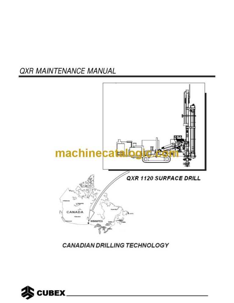
Model: QXR 1120 Surface Drill

Type of Document: Maintenance Manual

Category:

$ 45

Share:

Cubex QXR 1120 Surface Drill Maintenance Manual

Cubex QXR 1120 Surface Drill Maintenance Manual

📘 Show Index

Cubex QXR 1120 Surface Drill Index:

  • 1.1 Operating/Maintenance Safety
    • 1.1.1 Drill Operation and Maintenance Safety
    • 1.1.2 General Safety Instructions
    • 1.1.3 Safety Instructions for Driving and Operating
    • 1.1.4 Safety Instructions for Servicing
    • 1.1.6 Fluid and Filter Notices:
    • 1.1.7 Safety Reminders:
  • 2.1 Drill Assembly
  • 2.2 Break-in Maintenance
  • 2.3 Preventative Maintenance Program
    • 2.3.1 Lubrication
      • 2.3.1.1 Rock Drill Grease
      • 2.3.1.2 Lubrication Points and Intervals
      • 2.3.1.3 Lubrication Types
      • 2.3.1.4 Lubrication Cross-over
      • 2.3.1.5 QXR Automatic Lubrication System
    • 2.3.2 Bolt Torque
    • 2.3.3 Drill Filtration Points and Intervals
    • 2.3.4 Pipe Thread Grease Pump
      • 2.3.4.1 Safety
      • 2.3.4.2 Maintenance
  • 2.4 Recommended Tools:
  • 3.1 Track Adjustment
  • 3.2 Final Drive
  • 4.1 Mast Feed System
    • 4.1.1 QXR Feed Chain Adjustment
    • 4.1.2 Slider Adjustment
    • 4.1.3 Carrier Block
    • 4.1.4 Feed Chain Block
    • 4.1.5 Jib Boom
    • 4.1.6 Triple Jaw Breakout (TJBO)
      • 4.1.6.1 Overhaul procedure
  • 4.2 Top Drive
    • 4.2.1 Using the Right Equipment
    • 4.2.2 Checking Bearing Pre-load
    • 4.2.3 Adjusting Bearing Pre-load
    • 4.2.4 Removing Top Drive
    • 4.2.5 Disassembly Procedure
    • 4.2.6 Assembly Procedure
      • 4.2.6.1 Lower Gear Housing Assembly
      • 4.2.6.2 Upper Gear Housing Assembly
      • 4.2.6.3 Driveshaft Assembly
      • 4.2.6.4 Final Assembly
    • 4.2.7 Top Drive Installation
    • 4.2.8 Saver Sub Field Procedures
      • 4.2.8.1 Removal
      • 4.2.8.2 Installation
    • 4.2.9 Air Swivel Field Procedures
      • 4.2.9.1 Removing Air Swivel
      • 4.2.9.2 Installation of Air Swivel
      • 4.2.9.3 Dismantling Air Swivel
      • 4.2.9.4 Assembly Procedure
      • 4.2.9.5 Inspection of Parts
  • 4.3 Top Drive Motor
  • 4.4 Breakout Wrench
  • 4.5 Carousel Assembly
    • 4.5.1 Carousel Adjustment
      • 4.5.1.1 Pipe Clamp Adjustment
      • 4.5.1.2 Clamp Arm Adjustment
  • 4.6 Expander Pin System – Mast Boom
    • 4.6.1 Torque and Maintenance Intervals
      • 4.6.1.2 Torque Schedule
      • 4.6.1.3 Mounting/Dismounting Tools
      • 4.6.1.4 Installation
      • 4.6.1.5 Dismounting
  • 5.1 Hydraulic Symbols
    • 5.1.1 Hydraulic Schematic
  • 5.2 Hydraulic Circuits
  • 5.3 Hydraulic Pump
    • 5.3.1 Installation
      • 5.3.1.1 Pre Start-up
      • 5.3.1.2 Start-up
    • 5.3.2 Adjustments
      • 5.3.2.1 System (Operating) Pressure Adjustment
      • 5.3.2.2 Stand-by Pressure Adjustment
    • 5.3.3 Testing the Pump
    • 5.3.4 Troubleshooting the Pump
    • 5.3.5 Factors Affecting the Pump’s Life
      • 5.3.5.1 Contaminated Fluid
      • 5.3.5.2 Poor Suction Conditions
      • 5.3.5.3 Excessive Case Pressure
      • 5.3.5.4 Too Low an Operating Pressure
      • 5.3.5.5 Cavitation/Aeration
  • 5.4 Hydraulic Cylinders
    • 5.4.1 Double Acting Cylinders
    • 5.4.2 Cylinder Inspection
    • 5.4.3 Cylinder Overhaul
  • 5.5 Control Valves – On/Off Types
    • 5.5.1 Control Valves
    • 5.5.2 Relief Valve Adjustment
    • 5.5.3 Valve Pressure Adjustment
    • 5.5.4 Valve Flow Adjustment
    • 5.5.5 Valve Overhaul
    • 5.5.6 Valve Sections
    • 5.5.7 Solenoid
    • 5.5.8 Lever Section
    • 5.5.9 Valve Assembly
    • 5.5.10 Inlet Section
  • 5.6 Manifold Blocks
    • 5.6.1 Servicing Cartridge Valves
    • 5.6.2 Troubleshooting Cartridge Valves
    • 5.6.3 Installation Torque Values
  • 5.7 Counterbalance Valves
    • 5.7.1 Making Adjustments
    • 5.7.2 Troubleshooting
  • 5.8 Hydraulic Filtration
    • 5.8.1 Change Hydraulic Fluid Every 2000 Hours
    • 5.8.2 Return Filters
    • 5.8.3 Pressure Filter Element
  • 5.9 Proportional Valves
    • 5.9.1 Proportional Valve Settings
    • 5.9.2 Flow Settings
    • 5.9.3 Pressure Setting
  • 6.1 Air Schematic
  • 6.2 Sullair Compressor
    • 6.2.1 Compressor Unit Functional Description
    • 6.2.2 Compressor Discharge System Functional Description
    • 6.2.3 Compressor Cooling and Lubrication System Functional Description
    • 6.2.4 Air Inlet System Functional Description
    • 6.2.5 Lubrication Guide
    • 6.2.6 Application Guide
    • 6.2.7 Control System
      • 6.2.7.1 Purpose of Controls
      • 6.2.7.2 Butterfly Inlet Valve Functional Description
      • 6.2.7.3 Closed Inlet Start Program
      • 6.2.7.4 Normal Operation
      • 6.2.7.5 Modulation
      • 6.2.7.6 Unload
      • 6.2.7.7 Compressor Start Up Mode and Running Mode Low Air Pressure
      • 6.2.7.8 Manual Unload Mode
      • 6.2.7.9 Running Mode 350 psi Air Pressure
      • 6.2.7.10 Running Mode 500 psi Air Pressure
      • 6.2.7.11 Instrumentation and Protection
      • 6.2.7.12 Start Up and Shutdown Procedures
      • 6.2.7.13 Adjustment Procedures
    • 6.2.8 Compressor Maintenance
      • 6.2.8.1 Main Fluid Filter Service
      • 6.2.8.2 Thermal/Bypass Valve
      • 6.2.8.3 Separator Element Replacement
      • 6.2.8.4 Running Blowdown Valve Maintenance
      • 6.2.8.5 Shutdown Blowdown Valve Maintenance
      • 6.2.8.6 Minimum Pressure/Check Valve Maintenance
      • 6.2.8.7 Discharge Check Valve Maintenance
      • 6.2.8.8 Safety Valve
      • 6.2.8.9 Pressure Regulator (Low / High Air Pressure Regulator)
      • 6.2.8.10 Fluid Stop Valve
    • 6.2.9 Screw Compressor
      • 6.2.9.1 Screw Compressor Arrangement
      • 6.2.9.2 Compressor Operator Daily Checklist
      • Compressor Operator Daily Checklist
      • 6.2.9.3 Maintenance Schedules
      • 6.2.9.4 Compressor Lubrication Crossover
      • 6.2.9.5 Compressor Troubleshooting
  • 6.3 Water Pump
    • 6.3.1 Pump Speed Adjustment
    • 6.3.2 Preventative Maintenance
    • 6.3.3 Troubleshooting the Water Pump
    • 6.3.4 Service Procedures
    • 6.3.5 Water Pump Coupling Annual Maintenance
      • 6.3.5.1 Periodic Lubrication
  • 6.4 Grease Injection
    • 6.4.1 To Fill Reservoir
    • 6.4.2 To Prime System
    • 6.4.3 Operation
    • 6.4.4 Adjusting Flow Rate
      • 6.4.4.1 Setting for a 4” Hammer
      • 6.4.4.2 Setting for a 6” Hammer
    • 6.4.5 PanelView Settings for QXR
  • 7.1 Electrical Circuits
  • 7.2 Electrical Components
  • 7.3 On/Off Valve Activation
  • 7.4 Types of Valves
  • 7.5 Testing of Valve Solenoids
  • 7.6 Testing On/Off Valves
  • 7.7 Proportional Valves
  • 7.8 Fault Monitoring System
    • 7.8.1 Testing Proportional Valves
  • 7.9 Accra-Feed Control System
    • 7.9.1 Accra-Feed Operation
    • 7.9.2 Accra-Feed Components
    • 7.9.3 PLC Operation
    • 7.9.4 Maintenance of PLC in Accra-Feed System
    • 7.9.5 Troubleshooting Guide
  • 7.10 Operator Interface PanelView 1000
    • 7.10.1 Maintenance of PanelView Terminal
    • 7.10.2 Troubleshooting PanelView Terminal
    • 7.10.3 Alarm Messages on the Terminal
  • 7.11 QXR Canbus Electrical System
    • 7.11.1 Components
      • 7.11.1.1 Cab Control Panel
      • 7.11.1.2 Rear Control Panel
      • 7.11.1.3 PanelView
      • 7.11.1.4 Joysticks
      • 7.11.1.5 Mast Sensor Junction Box
      • 7.11.1.6 Carousel Junction Box
      • 7.11.1.7 10-Channel Low-Pass Filter Module
    • 7.11.2 Canbus Components
      • 7.11.2.1 Vansco Multiplexing Module (VMM) 1210 Multiplexing Module
      • 7.11.2.2 Pocket Gateway Module (PGM)
    • 7.11.3 Operation
    • 7.11.4 VMM 1210 Hardware and Software
      • 7.11.4.1 Hardware
      • 7.11.4.2 VMM 1210 Software
      • 7.11.4.3 Updating the VMM1210 Software
      • 7.11.4.4 PC Software Installation
    • 7.11.5 Functions
      • 7.11.5.1 QXR Input/Output List – Cab Control Panel – VMM1 PLC22
      • 7.11.5.2 QXR Input/Output List – Cab Control Panel – VMM2 PLC62
      • 7.11.5.3 QXR Input/Output List – Cab Control Panel VMM3 PLC102
      • 7.11.5.4 QXR Input/Output List – Rear Control Panel VMM4 PLC222
      • 7.11.5.5 QXR Input/Output List – Rear Control Panel VMM5 PLC262
      • 7.11.5.6 QXR Input/Output List – Rear Control Panel VMM6 PLC302
      • 7.11.5.7 QXR Input/Output List – Rear Control Panel VMM7 PLC342
      • 7.11.5.8 QXR Input/Output List – Rear Control Panel VMM8 PLC382
      • 7.11.5.9 QXR Input/Output List – Rear Control Panel VMM9 PLC422
      • 7.11.5.10 QXR Input/Output List – Mast Valve Junction Box VMM10 PLC482
      • 7.11.5.11 QXR Input/Output List – Mast Valve Junction Box VMM11 PLC522
      • 7.11.5.12 QXR Input/Output List – Mast Sensor Junction Box VMM12 PLC582
  • 8.0 Troubleshooting
  • 8.1 Troubleshooting the Tram Drive
    • Crawler Does Not Run but Tramming Motors Are Operating
    • Crawler Does Not Move and Tramming Motor Does Not Run
    • Crawler Does Not Tram Straight
  • 8.2 Troubleshooting the Hydraulic System
    • Pump Does Not Deliver Oil
    • Pump is Running Hot
    • Cavitation or Pump Noise
    • Insufficient Pressure
    • Slow Rotation at Top Drive
    • No Rotation at Top Drive Assembly
    • Slow or No Feed
    • Mast Does Not Rotate
    • Actuator Allows Mast to Move After Being Set
  • 8.3 Troubleshooting the Water Injection Pump
    • Discharge Pressure is Too Low
    • Cavitation Problems
    • No Water Discharge
    • Excessive Pump Noise
  • 8.4 Troubleshooting the Air Driven Oil Injection Pump
    • Air Motor Does Not Operate
    • Air Seepage from Air Exhaust While Pump is Not Working
    • Loss of Pressure, Volume, or Continuous Operation of Pump when Not in Normal Use
    • Excessive Amount of Air in Lubricant or Excessive Amount of Lubricant in Air
  • 8.5 Troubleshooting the Air Driven Grease Injection
    • Air Motor Does Not Operate
    • Grease Is Not Delivered to the Drilling Air Line
  • 8.6 Troubleshooting the Air Delivery System
    • Air Pressure Builds too Slowly
    • Compressor Shuts Down with Air Demand Present
    • Compressor Does Not Build-Up Full Discharge Pressure
    • Compressor Unloading with an Excessive Pressure Build-Up
    • Excessive Compressor Fluid Consumption
    • Compressor Overheating
  • 8.7 Troubleshooting the Hammer
    • Tool Does Not Start
    • Tool Stops Operating
    • Operating Pressure is Lower than Specifications
    • Low Penetration Rate
    • Galling of Internal Parts
  • 8.8 Troubleshooting the Drill Bit
    • Abrasive Wear
    • Loss of Carbides in Bit
    • Bit Breakage and Carbide Failure
    • Carbide Breakage
    • Uneven Wear Conditions
  • 8.9 Troubleshooting Depth Laser
    • Laser appears not working. No red light is coming out of aperture.
    • Laser appears working; red light is pulsing in even intervals, no output signal.
    • Laser appears working, red light is pulsing but in un-even intervals
    • General notes:

Cubex


Latest Product

0
    0
    Your Cart
    Your cart is emptyReturn to Shop