$ 0
0
$ 0
0

Cubex QXR 1120 10305 Surface Drill Operators Manual

Format: PDF (Printable Document)

File Language: English
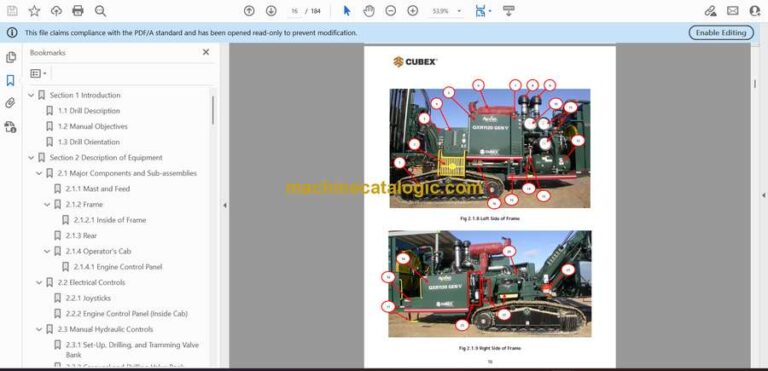
File Pages: 184

File Size: 12.06 MB (Speed Download Link)
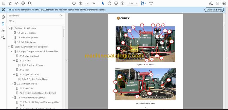
Brand: Cubex

Model: QXR 1120 10305 Surface Drill

Type of Document: Operators Manual

Category:

$ 45

Share:

Cubex QXR 1120 10305 Surface Drill Operators Manual

Cubex QXR 1120 10305 Surface Drill Operators Manual

Out on a bench or quarry face, this Cubex surface drill spends its life working hard on uneven ground, around loose rock and tight patterns. This operators manual is what I’d keep handy to understand how the controls should feel, how the machine should react under load, and what to check before and after a shift. If, for example, the feed isn’t tracking straight or the rotation bogs when you start a hole, this is the reference I’d use to verify proper operating steps before assuming there’s a mechanical failure.

Applications & Use Cases

  • Daily walk‑around checks so you catch leaks, loose hardware or damaged hoses before they turn into downtime.
  • Learning control functions to smoothly start, stop and adjust drilling on sloped or broken ground without shocking the structure.
  • Optimizing drilling technique to keep bit life up and avoid stalling or binding in hard or fractured rock.
  • Understanding machine reactions under load so you can tell normal vibration from a problem that needs inspection.
  • Training new operators to use safe habits around the mast, rotation head and moving tracks.

FAQ

Q: Can I keep this manual on a tablet in the cab?

A: Yes, it’s practical to use digitally; you can zoom diagrams and quickly search terms while the drill is parked.

Q: Is it worth printing parts of this manual?

A: Many crews print the daily checklists and control overviews, laminate them, and keep them in the service truck or cab for quick reference.

Safety Note

Always follow the manual’s operating steps and lockout procedures before working near the mast, rotation head or any pressurized system.

📘 Show Index

Cubex QXR 1120 10305 Surface Drill Index:

  • Section 1 Introduction
    • 1.1 Drill Description
    • 1.2 Manual Objectives
    • 1.3 Drill Orientation
  • Section 2 Description of Equipment
    • 2.1 Major Components and Sub-assemblies
      • 2.1.1 Mast and Feed
      • 2.1.2 Frame
        • 2.1.2.1 Inside of Frame
      • 2.1.3 Rear
      • 2.1.4 Operator’s Cab
        • 2.1.4.1 Engine Control Panel
    • 2.2 Electrical Controls
      • 2.2.1 Joysticks
      • 2.2.2 Engine Control Panel (Inside Cab)
    • 2.3 Manual Hydraulic Controls
      • 2.3.1 Set-Up, Drilling, and Tramming Valve Bank
      • 2.3.2 Carousel and Drilling Valve Bank
    • 2.4 Display Screens
      • 2.4.1 System Screen
      • 2.4.2 Status Bar
      • 2.4.3 Menu Buttons
      • 2.4.4 Status Indicator
      • 2.4.5 QXR Shutdowns and Warnings
      • 2.4.6 Configuration Menu
        • 2.4.6.1 Tram Settings
        • 2.4.6.2 Make-up / Breakout Settings
        • 2.4.6.3 Weight on Bit Settings
        • 2.4.6.4 Hourmeter Settings
        • 2.4.6.5 Accra-Feed Configuration Settings
        • 2.4.6.6 Lube/Grease/Water Configuration Settings
        • 2.4.6.7 Pre-set Configuration – Setting Hole Depth
        • 2.4.6.8 Miscellaneous Settings
        • 2.4.6.9 Diagnostic Screen
      • 2.4.7 Tramming and Oscillation
      • 2.4.8 Set-up Screens
        • Set-up Screen – Layer 1
        • Set-up Screen – Layer 2
        • Set-up Screen – Layer 3
      • 2.4.9 Drill Screens
        • Drill Screen – Layer 1
        • Drill Screen – Layer 2
        • Drill Screen – Layer 3
        • Drill Screen – Manual Drilling Layer 1
      • 2.4.10 Accra-Feed Screen – Layer 1
  • Section 3 Start-Up and Tramming
    • 3.1 Operating Procedures for Start-Up
      • 3.1.1 Pre-start Inspection
      • QXR Operator Pre-Start Checklist
    • 3.2 Start-Up
      • 3.2.1 Inside Cab
      • 3.2.2 Outside Cab
    • 3.3 Tramming
      • 3.3.1 Tramming from the Tram Station
      • 3.3.2 Tramming from the Cab
      • 3.3.3 Tramming Stability
    • 3.4 Set-up
      • 3.4.1 Set-Up from the Cab
      • 3.4.2 Indexing the Swing Cylinder
    • 3.5 Shutdown Procedure
    • 3.6 Towing
      • 3.6.1 Towing Guidelines and Precautions
      • 3.6.2 Tow Disconnect – Sun Gear Removal Procedure
      • 3.6.3 Sun Gear Re-install
  • Section 4 Drilling
    • 4.1 Drilling Procedures
      • 4.1.1 Hammer Installation Procedure
      • 4.1.2 Drill Pipe Installation (Adding Rods)
      • 4.1.3 Drill Pipe Removal
    • 4.2 Delivery Systems
      • 4.2.1 Water Injection Procedure
      • 4.2.2 Grease Injection Procedure
      • 4.2.3 Oil Injection Procedure
    • 4.3 Drilling
      • 4.3.1 Manual Drilling
      • 4.3.2 Drilling with Accra-Feed Feature (Optional)
  • Section 5 Maintenance and Safety
    • 5.1 Daily Maintenance Procedures
      • Safety Instructions for Servicing
        • REMEMBER
        • Fluid Notices
    • 5.2 Lubrication
      • 5.2.1 Rock Drill Grease
      • 5.2.2 Lubrication Points and Intervals
      • 5.2.3 Automatic Machine Lubrication
    • 5.3 Safety Procedures
      • 5.3.1 Personal Protection Equipment
      • 5.3.2 Overhead and Buried Utilities
      • 5.3.3 Ask for Assistance
      • 5.3.4 Safety Shutdowns
      • 5.3.5 Safety Labels
      • 5.3.6 General Safety and Maintenance Instructions
  • Section 6 Troubleshooting
    • 6.1 Troubleshooting the Tram Drive
      • Crawler Does Not Run but Tramming Motors Are Operating
      • Crawler Does Not Move and Tramming Motor Does Not Run
      • Crawler Does Not Tram Straight
    • 6.2 Troubleshooting the Hydraulic System
      • Pump Does Not Deliver Oil
      • Pump is Running Hot
      • Cavitation or Pump Noise
      • Insufficient Pressure
      • Slow Rotation at Top Drive
      • No Rotation at Top Drive Assembly
      • Slow or No Feed
      • Mast Does Not Rotate
      • Actuator Allows Mast to Move after Being Set
    • 6.3 Troubleshooting the Water Injection Pump
      • Discharge Pressure is Too Low
      • Cavitation Problems
      • No Water Discharge
      • Excessive Pump Noise
    • 6.4 Troubleshooting the Air Driven Oil Injection Pump
      • Air Motor Does Not Operate
      • Air Seepage from Air Exhaust While Pump is Not Working
      • Loss of Pressure, Volume, or Continuous Operation of Pump when Not in Normal Use
      • Excessive Amount of Air in Lubricant or Excessive Amount of Lubricant in Air
    • 6.5 Troubleshooting the Air Driven Grease Injection
      • Air Motor Does Not Operate
      • Grease Is Not Delivered to the Drilling Air Line
    • 6.6 Troubleshooting the Air Delivery System
      • Air Pressure Builds too Slowly
      • Compressor Shuts Down with Air Demand Present
      • Compressor Does Not Build-Up Full Discharge Pressure
      • Compressor Unloading with an Excessive Pressure Build-Up
      • Excessive Compressor Fluid Consumption
      • Compressor Overheating
    • 6.7 Troubleshooting the Hammer
      • Tool Does Not Start
      • Tool Stops Operating
      • Operating Pressure is Lower than Specifications
      • Low Penetration Rate
      • Galling of Internal Parts
    • 6.8 Troubleshooting the Drill Bit
      • Abrasive Wear
      • Loss of Carbides in Bit
      • Bit Breakage and Carbide Failure
      • Carbide Breakage
      • Uneven Wear Conditions
    • 6.9 Troubleshooting Depth Laser
      • Laser appears not working. No red light is coming out of aperture.
      • Laser appears working, red light is pulsing in even intervals, no output signal.
      • Laser appears working, red light is pulsing but in un-even intervals
      • General notes:
  • Cubex Terra DGS Operation Manual
  • Section 1 Introduction
    • 1.1 Features
  • Section 2 Software Removal and Installation
    • 2.1 Removal / Installation Procedure:
    • 2.2 Sensor Installation
      • 2.2.1 Installing Wires in Sensor Box
      • 2.2.2 Screen Installation
  • Section 3 Operation
    • 3.1 ZERO-OFFSET Calibration Procedure
    • 3.2 Local and Absolute Heading Measurements

Cubex


Latest Product

0
    0
    Your Cart
    Your cart is emptyReturn to Shop