Format: PDF (Printable Document)
File Language: English
File Pages: 168
File Size: 26.53 MB (Speed Download Link)
Brand: Kohler
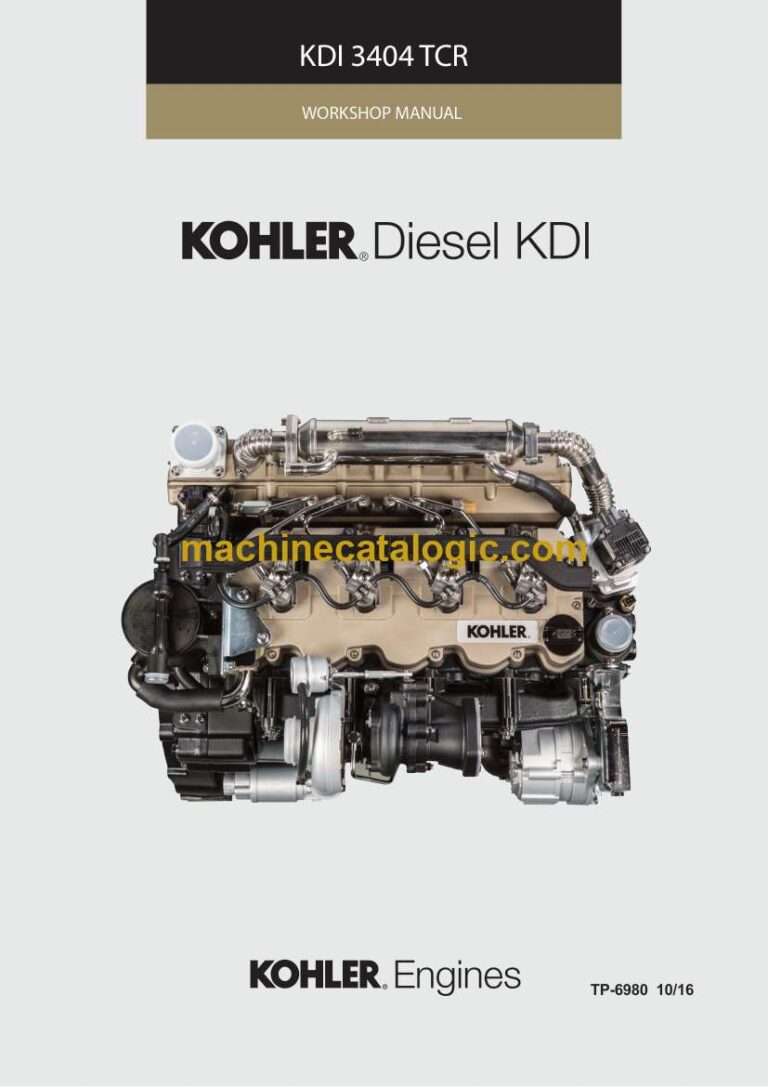
Model: KDI 3404 TCR Diesel
Book No: tp6980
Type of Document: Workshop Manual
$ 40
These KDI 3404 TCR engines usually live in rough places—loaders in gravel yards, telehandlers on construction sites, generators in dusty plants. This workshop manual is what I’d keep open on the bench when I’m tearing one down and putting it back together, so I don’t miss a critical shim, seal, or timing step. If you’re chasing a hard-start complaint after an injector swap or a top-end refresh, this book walks you through the proper teardown, inspection, and reassembly sequence so you fix it once instead of pulling it apart twice.
Applications & Use Cases
FAQ
Q: Can I use this manual on a tablet at the machine?
A: Yes, it works well digitally; you can zoom diagrams and keep it open while you trace hoses and harnesses on-site.
Q: Is it worth printing sections of this manual?
A: Definitely—most techs print just the procedures they’re doing that day and tape them to the cart to avoid greasy devices.
Safety Note
Always lock out the machine, support all heavy components securely, and never work under a suspended load when following these procedures.
1 GENERAL INFORMATION 11
1.1 Useful information 11
1.2 Manufacturer and engine identification 12
1.3 Name plate for EPA regulations 13
1.4 Identification of main internal components of the engine and operating references 14
1.5 Identification of external components of the engine 16
2 TECHNICAL INFORMATION 18
2.1 Engine specifications 18
2.2 Engine dimensions (mm) 20
2.3 Performance diagrams 21
2.4 Oil 22
2.4.1 SAE classification 22
2.4.2 International lubricant specifications 22
2.5 Fuel 23
2.5.1 Fuel for low temperatures 23
2.5.2 Biodiesel fuel 23
2.5.3 Emissions – Regarding installation instructions 24
2.6 Coolant 24
2.7 Battery features 24
2.8 Scheduled maintenance 25
2.9 Fuel system 26
2.9.1 Injection circuit (2000 bar) 26
2.9.2 Fuel return circuit 27
2.9.3 High-pressure injection pump (2000 bar) 28
2.9.4 Electronic injector 29
2.9.5 Common rail 30
2.9.6 Fuel filter 31
2.9.7 Electric fuel pump (optional) 32
2.9.8 Guards for fuel injection circuit components 33
2.10 Lubrication circuit 34
2.10.1 Lubrication circuit diagram 34
2.10.2 Oil pump 35
2.10.3 Lub. oil filter and Oil Cooler 36
2.11 Coolant circuit 37
2.11.1 Coolant circuit diagram 37
2.11.2 Coolant pump 38
2.11.3 Thermostatic valve 38
2.11.4 EGR gas circuit cooling (EGR Cooler) 38
2.12 Intake and exhaust circuit 39
2.12.1 Turbocharger 39
2.12.2 Catalyst (optional) 39
2.12.3 Intake and exhaust circuit diagram with EGR 40
2.13 Electric system 42
2.13.1 ECU input and output signals diagram 42
2.13.2 Control unit (ECU) 43
2.13.2.1 Installation rules 43
2.13.3 Engine electrical wiring 44
2.13.3.1 Wiring disconnection 45
2.14 Sensors and switches 47
2.14.1 Speed sensor on phonic wheel 47
2.14.2 Phase sensor indicator on camshaft 47
2.14.3 T-MAP sensor 47
2.14.4 Common Rail pressure sensor 47
2.14.5 Fuel filter water detection sensor 48
2.14.6 Fuel temperature sensor on fuel injection pump 48
2.14.7 Oil pressure switch 48
2.14.8 Coolant temperature sensor 48
2.15 Electrical components 49
2.15.1 Alternator 49
2.15.2 Poly-V belt alternator (optional) 49
2.15.3 Starter Motor 49
2.15.4 EGR valve 49
INDEX OF CHAPTERS
4
–
ED0053030470_03
INDEX OF CHAPTERS
2.15.5 Cold starting device 49
2.15.6 Fuel intake regulating valve (SCV) 50
2.15.7 Electric fuel pump (optional) 51
2.16 Timing system and tappets 52
2.16.1 Components identification 52
2.16.2 Timing system phasing angles 53
2.16.3 Rocker arm gudgeon 53
2.16.4 Rocker arm 53
2.16.5 Hydraulic tappets 54
2.16.5.1 Hydraulic tappet operation 54
2.16.5.2 Difficult operating conditions 54
2.17 Balancer device 55
2.18 Components handling 56
2.18.1 High-pressure fuel injection pump 56
2.18.2 Electronic injector 56
2.18.3 Common Rail 56
2.18.4 Turbocharger 56
2.19 Turbocharger 57
2.19.1 What to do and what not to do 57
2.19.2 Practical operating rules 57
2.19.3 Before installing a new turbocharger 58
2.19.4 Installation instructions 59
2.19.5 Replacement instructions 59
3 SAFETY INFORMATION 60
3.1 Pre-start check 60
3.2 Safety precautions 60
3.3 General remarks 60
3.3.1 Manufacturer’s notes 60
3.3.2 Notes for the end user 60
3.4 Safety label description 62
3.4.1 Adhesive safety plates 62
3.4.2 Warnings 62
3.4.3 Safety guards 62
3.5 Information and safety labels 63
3.6 Safety and environmental impact 63
3.7 Location of safety labels on engine 64
4 STORAGE INFORMATION 65
4.1 Product preservation 65
4.2 Engine storage (up to 6 months) 65
4.3 Engine storage (over 6 months) 65
4.4 Engine starting after storage 65
5 LIQUID DRAINAGE INFORMATION 67
5.1 Coolant liquid 67
5.2 Engine oil 67
6 INFORMATION FOR REPLACING FUNCTIONAL UNITS 69
6.1 Electronic injector replacement 69
6.1.1 Fuel return tubes disassembly (Common Rail/electronic injectors) 69
6.1.2 High pressure fuel tubes disassembly (Common Rail/electronic injectors) 70
6.1.3 Electronic injector disassembly 70
6.1.4 Electronic injector assembly 70
6.1.5 High-pressure fuel lines assembly 71
6.1.6 Fuel return tubes assembly 71
6.2 High-pressure fuel injection pump replacement 72
6.2.1 High pressure fuel tube disassembly (from injection pump to Common Rail) 72
6.2.2 High-pressure fuel injection pump disassembly 73
6.2.3 High-pressure fuel injection pump assembly 74
6.2.4 High-pressure line assembly (injection pump / Common Rail) 75
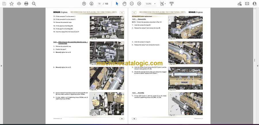
6.3 EGR cooler unit replacement 76
6.3.1 Disassembly 76
6.3.2 Assembly 76
6.4 EGR valve replacement 77
6.4.1 Disassembly 77
6.4.2 Assembly 77
6.5 Coolant pump replacement 78
6.5.1 Disassembly 78
6.5.2 Assembly 79
6.6 Target wheel replacement 79
6.6.1 Disassembly 79
6.6.2 Assembly 80
6.7 Oil steam separator replacement 81
6.7.1 Disassembly 81
6.7.2 Assembly 81
6.8 Oil Cooler Unit and lub. oil filter replacement 82
6.8.1 Oil Cooler unit disassembly 82
6.8.2 Oil filter cartridge replacement 82
6.8.3 Oil Cooler unit assembly 83
6.9 Fuel filter replacement 84
6.9.1 Disassembly 84
6.9.2 Assembly 84
7 INFORMATION FOR DISASSEMBLY 86
7.1 Recommendations for disassembly 86
7.2 EGR circuit disassembly 86
7.2.1 EGR Cooler Unit 86
7.3 Coolant recirculation components disassembly 87
7.3.1 Oil Cooler manifold 87
7.3.2 Coolant pump 87
7.3.3 Thermostatic valve 87
7.4 Electric components disassembly 88
7.4.1 Electric wiring 88
7.4.2 Starter motor 89
7.4.3 Belt and alternator 89
7.4.4 EGR Valve 89
7.4.5 Sensors and switches 90
7.4.5.1 Oil pressure switch 90
7.4.5.2 Coolant temperature sensor 90
7.4.5.3 Speed sensor 90
7.4.5.4 Camshaft phase sensor 90
7.4.5.5 T-MAP sensor 91
7.4.5.6 Fuel filter water detection sensor 91
7.5 Turbocharger disassembly 91
7.6 Exhaust manifold disassembly 92
7.7 Crankshaft and target wheel pulley disassembly 92
7.8 Flange unit disassembly 92
7.8.1 Flywheel 92
7.8.2 Flange bell 92
7.9 Lubrication circuit disassembly 93
7.9.1 Oil pump 93
7.9.2 Oil pressure valve 93
7.9.3 Oil Cooler Unit and lub. oil filter 93
7.9.4 Oil steam separator unit 93
7.10 Fuel system disassembly 94
7.10.1 Fuel return tubes 94
7.10.2 Fuel flow tubes 94
7.10.3 High-pressure fuel lines 94
7.10.4 Common rail 95
7.10.5 Electronic injectors 95
7.10.6 Fuel filter 95
7.10.7 High-pressure fuel injection pump 96
7.11 Intake manifold disassembly 96
6
–
ED0053030470_03
7.12 Cylinder head unit disassembly 97
7.12.1 Rocker arm cover 97
7.12.2 Rocker arm gudgeon 97
7.12.2.1 Rocker arms 97
7.12.3 Valve rods and bridges 97
7.12.4 Cylinder head 98
7.12.4.1 Valves 98
7.12.4.2 Electronic injector sleeves 99
7.12.4.3 Valve stem gasket 99
7.12.4.4 Lifting eyebolts 99
7.13 Timing system gear disassembly 100
7.14 Oil sump unit disassembly 100
7.14.1 Oil sump 100
7.14.2 Oil suction pipe 100
7.14.3 Oil drain pipe 100
7.15 Short block disassembly 101
7.15.1 Piston unit / connecting rod and crankshaft 101
7.15.2 Lower crankcase 102
7.15.3 Crankshaft 103
7.15.4 Piston 103
7.15.4.1 Rings 104
7.15.5 Oil spray nozzles 104
7.15.6 Camshaft tappets 104
7.15.7 Crankshaft bushings 105
8 INFORMATION ABOUT OVERHAULING AND TUNING 106
8.1 Recommendations for overhauls and tuning 106
8.2 Crankcase 106
8.2.1 Oil tubes check 106
8.2.2 Cylinders Check 107
8.2.3 camshaft housing check 108
8.2.4 camshaft check 108
8.3 Tappets and tappet housings 109
8.3.1 Tappets check 109
8.3.2 Tappet housing check 109
8.4 Crankshaft 110
8.4.1 Dimensional check and overhauling 110
8.4.2 Check the axial clearance of the crankshaft 111
8.5 Connecting rod-piston 111
8.5.1 Connecting rod dimension check 111
8.5.2 Checking the gudgeon pin-pin axes are parallel 112
8.5.3 Piston rings check 112
8.5.4 Piston dimension check 112
8.6 Cylinder head 113
8.6.1 Flatness check 113
8.6.2 Valve seats check 114
8.6.3 Valve springs 114
8.6.4 Valve guides check 114
8.6.5 Valve guides replacement 115
8.6.6 Controllo bilancieri 115
8.7 Oil pump check 116
8.7.1 Rotors clearance check 116
8.7.2 Oil pressure valve check 116
9 ASSEMBLY INFORMATION 117
9.1 Information on engine configuration 117
9.2 Assembly recommendations 117
9.3 Short block assembly 118
9.3.1 Crankshaft bushings 118
9.3.2 Tappets 118
9.3.3 Oil spray nozzles 118
9.3.4 Crankshaft 119
9.3.6 Camshaft 121
9.3.7 Rings 122
9.3.8 Piston 122
9.3.9 Piston and connecting rod unit 123
9.4 Oil sump unit assembly 125
9.4.1 Oil drain pipe 125
9.4.2 Oil suction pipe 125
9.4.3 Oil Sump 125
9.5 Cylinder head unit assembly 126
9.5.1 Valve stem gasket 126
9.5.2 Electronic injector sleeves 126
9.5.3 Electronic injector projection 127
9.5.4 Valves 127
9.5.5 Cylinder head 127
9.5.6 Valve rods and bridges 129
9.5.7 Rocker arm 130
9.5.8 Rocker arm gudgeon unit 130
9.5.9 Rocker arm cover 131
9.6 Intake manifold assembly 132
9.6.1 Internal half-manifold 132
9.6.2 External half-manifold 132
9.7 Fuel system assembly 132
9.7.1 High-pressure fuel injection pump 132
9.7.2 Fuel filter 133
9.7.3 Electronic injectors 133
9.7.4 Common Rail 134
9.7.5 High-pressure fuel lines 134
9.7.6 Fuel flow tubes 135
9.7.7 Fuel return tubes 135
9.8 Lubrication circuit assembly 136
9.8.1 Oil steam separator unit 136
9.8.2 Oil Cooler unit and lub. oil filter 136
9.8.3 Oil pressure valve 137
9.8.4 Oil pump 137
9.9 Flange unit assembly 138
9.9.1 Flange bell 138
9.9.2 Flywheel 138
9.10 Exhaust manifold assembly 139
9.11 Crankshaft and phonic wheel pulley unit 139
9.12 Turbocharger assembly 140
9.13 Electric components assembly 141
9.13.1 Sensors and switches 141
9.13.1.1 T-MAP sensor 141
9.13.1.2 Water temperature sensor 141
9.13.1.3 Oil pressure switch 141
9.13.1.4 Camshaft phase sensor 141
9.13.1.5 Speed sensor 142
9.13.1.6 Fuel filter water detection sensor 142
9.13.2 EGR valve 143
9.13.3 Alternator 143
9.13.4 Starter motor 143
9.13.5 Electric cabling 144
9.14 Coolant circuit assembly 146
9.14.1 Thermostatic valve 146
9.14.2 Water pump 146
9.14.3 Oil Cooler Manifold 146
9.15 EGR circuit assembly 147
9.15.2 EGR Cooler Unit 147
INDEX OF CHAPTERS
8
–
ED0053030470_03
10 FLUIDS FILLING INFORMATION 152
10.1 Engine oil 152
10.2 Coolant 152
11 INFORMATION ABOUT OPTIONAL COMPONENTS 153
11.1 Heater (replacement) 153
11.1.1 Disassembly 153
11.1.2 Assembly 153
11.2 Idler gear (for 3rd / 4th PTO) 154
11.2.1 Disassembly 154
11.2.2 Assembly 154
11.3 III PTO (replacement) 155
11.3.1 Disassembly 155
11.3.2 Assembly 155
11.4 IV PTO (replacement) 155
11.4.1 Disassembly 155
11.4.2 Assembly 155
11.5 Balancer device (replacement) 156
11.5.1 Disassembly 156
11.5.2 Assembly 156
12 INFORMATION REGARDING REGULATIONS 157
12.1 Waste Gate opening valve regulation 157
12.2 Air filter check 158
12.3 Oil steam separator check 158
12.4 Rubber hose and manifold control 158
12.5 Oil leak check 159
12.6 Oil pressure check 159
13 INFORMATION REGARDING TOOLS 161
13.1 Information regarding specific tools 161
14 INFORMATION REGARDING FAILURES 162


