Format: PDF (Printable Document)
File Language: English
File Pages: 143
File Size: 22.34 MB (Speed Download Link)
Brand: Kohler
Model: KDI 3404 TM Diesel
Book No: tp6983
Type of Document: Workshop Manual
$ 40
These KDI 3404 TM diesels usually live in rough places—loaders in quarries, telehandlers on construction sites, generators in dusty yards—running hard and long. This workshop manual is what I’d pull out when we’re doing a full top‑end or bottom‑end job and can’t afford to redo anything. It walks you through how to strip, inspect, and rebuild the engine in a logical order, so you don’t miss a seal, mis-time the gear train, or forget a critical torque step. For example, if you’ve got hard starting, low power, and blow-by, this is the guide I’d use to tear down, check wear points, and reassemble so it starts right the first time.
Applications & Use Cases
FAQ
Q: Can I use this manual on a tablet in the field?
A: Yes, it works well digitally; you can zoom diagrams and use search to jump straight to the system you’re working on.
Q: Is it worth printing sections of this manual?
A: Many techs print the procedures they’re doing that day, so they can mark notes, keep them next to the engine, and avoid getting a device oily.
Safety Note
Always follow the manual’s lifting, locking, and pressure-relief instructions before loosening or removing any major engine component.
1.1 Useful information 11
1.1.1 Useful Information -accident prevention – environmental impact 11
1.2 Manufacturer and engine identification 12
1.3 Name plate for EPA regulations 13
1.4 Identification of the main internal components of the engine and operating reference
(BASE CONFIGURATION)
14
1.5 Identification of the external components of the engine (BASE CONFIGURATION) 16
2 TECHNICAL INFORMATION 18
2.1 Engine specifications 18
2.2 Engine dimensions (mm) 20
2.3 Performance 21
2.4 Oil 22
2.4.1 SAE oil classification 22
2.4.2 International lubricant specifications 22
2.5 Fuel 23
2.5.1 Fuel for low temperatures 23
2.5.2 Biodiesel fuel 23
2.5.3 Emission-Related Installation Instructions 24
2.6 Coolant 24
2.7 Battery features 24
2.8 Periodic maintenance 25
2.9 Fuel system 26
2.9.1 Supply system 26
2.9.2 Fuel return circuit 27
2.9.3 Injection pump 27
2.9.4 Injector 28
2.9.5 Fuel filter 28
2.9.6 Electric fuel pump (optional) 29
2.9.7 Guards for fuel injection circuit components 29
2.10 Lubrication circuit 30
2.10.1 Lubrication circuit diagram 30
2.10.2 Oil pump 31
2.10.3 Oil filter and Oil Cooler 32
2.11 Coolant circuit 33
2.11.1 Coolant circuit diagram 33
2.11.2 Coolant pump 34
2.11.3 Thermostatic valve 34
2.11.4 Radiator (optional) 35
2.12 Intake and exhaust circuit 36
2.12.1 Intake and exhaust circuit diagram with Intercooler 36
2.12.2 Intake and exhaust circuit diagram without Intercooler 37
2.12.3 Turbocharger 37
2.12.4 Air filter (optional) 38
2.12.5 Internal EGR 38
2.13 Electric system 39
2.13.1 Engine electrical wiring (opzional) 39
2.13.1.1 Connector panel on the engine/machine 40
2.13.1.2 Accessories panel connector 40
2.13.1.3 Wiring disconnection 41
2.14 Sensors and switches 42
2.14.1 Fuel filter water detection sensor 42
2.14.2 Oil pressure switch 42
2.14.3 Coolant temperature sensor 42
2.14.4 Air cleaner clogging switch 43
2.15 Electrical components 43
2.15.1 Alternator 43
2.15.2 Starter motor 43
2.15.3 Cold starting device (Heater) 43
2.15.4 Electric fuel pump (optional) 44
2.15.5 Cold Start Advance 45
2.15.6 Electro-Stop 45
2.15.7 Starting Relay 45
INDEX OF CHAPTERS
4
–
ED0053030410_04
INDEX OF CHAPTERS
2.15.8 Fuse 45
2.15.9 Control panel (optional) 45
2.16 Timing system and tappets 46
2.16.1 Components identification 46
2.16.2 Timing system phasing angles 47
2.16.3 Rocker arm pin 47
2.16.4 Rocker arms 47
2.16.5 Hydraulic tappets 48
2.16.5.1 Hydraulic tappet operation 48
2.16.5.2 Difficult operating conditions 48
2.17 Components handling 49
2.17.1 Injection pump 49
2.17.2 Injector 49
2.17.3 Turbocharger 49
2.18 Turbocharger 50
2.18.1 What to do and what not to do 50
2.18.2 Practical operating rules 50
2.18.3 Before installing a new turbocharger 51
2.18.4 Installation instructions 52
2.18.5 Replacement instructions 52
3 SAFETY INFORMATION 53
3.1 Before start-up 53
3.2 Safety precautions 53
3.3 General remarks 53
3.3.1 Note for OEM 53
3.3.2 Note for end user 53
3.4 Safety signal description 55
3.4.1 Adhesive safety plates 55
3.4.2 Warnings 55
3.4.3 Safety guards 55
3.5 Information and safety signals 56
3.6 Safety and environmental impact 56
3.7 Location of safety signals on engine 57
4 STORAGE INFORMATION 58
4.1 Product preservation 58
4.2 Engine storage (up to 6 months) 58
4.3 Engine storage (over 6 months) 58
4.4 Engine starting after storage 58
5 INFORMATION REGARDING DISCHARGE OF LIQUIDS 60
5.1 Coolant 60
5.2 Engine oil 61
6 INFORMATION FOR REPLACING THE FUNCTIONAL UNITS 62
6.1 Injector and injection pump replacement 62
6.1.1 Injection fuel pipes disassembly(injection pump/injectors) 62
6.1.2 Rocker arms cover disassembly 62
6.1.3 Fuel return pipes disassembly 63
6.1.4 Injectors disassembly 63
6.1.5 Injection pump disassembly 63
6.1.6 Injection pump assembly 66
6.1.7 Injector assembly 67
6.1.8 Assembly of the injector return pipes 68
6.1.9 Assembly Rocker arm cover 69
6.1.10 Installation of the fuel injector pipes (pump injector/injectors) 69
6.2 Coolant pump replacement 70
6.2.1 Disassembly 70
6.2.2 Assembly 71
6.3 Oil vapour separator replacement 72
6.3.1 Disassembly 72
6.3.2 Assembly 72
6.4 Oil cooler unit and oil filter replacement 73
6.4.1 Oil Cooler unit disassembly 73
6.4.2 Oil filter cartridge replacement 73
6.4.3 Oil Cooler unit assembly 74
6.5 Fuel filter replacement 75
6.5.1 Disassembly 75
6.5.2 Assembly 75
7 DISASSEMBLY INFORMATION 77
7.1 Recommendations for disassembly 77
7.2 Turbocharger disassembly 77
7.3 Coolant recirculation components disassembly 78
7.3.1 Oil Cooler manifold 78
7.3.2 Thermostatic valve 78
7.3.3 Coolant pump 78
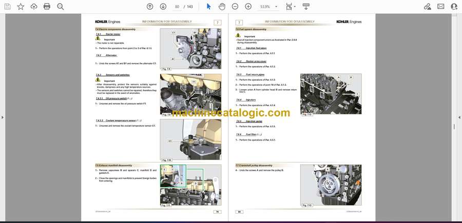
7.4 Electric components disassembly 79
7.4.1 Electric wiring 79
7.4.2 Starter motor 79
7.4.3 Belt and alternator 79
7.4.3.1 Oil pressure switch disassembly 79
7.4.3.2 Coolant temperature sensor 79
7.5 Exhaust manifold disassembly 79
7.6 Fuel system disassembly 80
7.6.1 Fuel injection pipes 80
7.6.2 Rocker arm cover 80
7.6.3 Fuel return pipes 80
7.6.4 Injector 80
7.6.5 Injection pump 80
7.6.6 Fuel filter 80
7.7 Crankshaft pulley disassembly 80
7.8 Flange unit disassembly 81
7.8.1 Flywheel 81
7.8.2 Flange housing 81
7.9 Lubrication circuit disassembly 81
7.9.1 Oil pump 81
7.9.2 Oil pressure valve 81
7.10 Cylinder head unit disassembly 82
7.10.1 Rocker arm pin 82
7.10.1.1 Rocker arm 82
7.10.2 Valve rods and bridges 82
7.10.3 Cylinder head 83
7.10.3.1 Valves 83
7.10.3.2 Injector sleeve 84
7.10.3.3 Valve stem gasket 84
7.10.3.4 Lifting eyebolts 84
7.11 Oil sump unit disassembly 85
7.11.1 Oil sump 85
7.11.2 Oil intake pipe 85
7.11.3 Oil drain pipe 85
7.12 Engine block disassembly 86
7.12.1 Piston unit / connecting rod 86
7.12.2 Timing system gear disassembly 87
7.12.3 Lower semi-crankcase 88
7.12.4 Crankshaft 89
7.12.5 Piston 89
7.12.5.1 Rings 89
7.12.6 Oil spray nozzles 89
7.12.7 Camshaft 90
7.12.8 Camshaft tappets 90
7.12.9 Crankshaft bushings 90
6
–
ED0053030410_04
8 INFORMATION ABOUT OVERHAULING 91
8.1 Recommendations for overhauls and tuning 91
8.2 Crankcase 91
8.2.1 Oil line check 91
8.2.2 Cylinder check 92
8.2.3 Camshaft housing check 93
8.2.4 Camshaft control 93
8.2.5 Camshaft control with internal EGR 93
8.3 Tappets and tappet housings 94
8.3.1 Tappets check 94
8.3.2 Tappet housing check 94
8.4 Crankshaft 95
8.4.1 Dimensional check and overhauling 95
8.4.2 Checking the axial clearance of the crankshaft 96
8.5 Connecting rod – piston assembly 96
8.5.1 Connecting rod dimensions check 96
8.5.2 Checking the gudgeon pin-pin axes are parallel 97
8.5.3 Piston rings check 97
8.5.4 Piston dimension check 97
8.6 Cylinder head 98
8.6.1 Flatness check 98
8.6.2 Valve seats check 99
8.6.3 Valve springs 99
8.6.4 Valve guides check 99
8.6.5 Valve guides replacement 100
8.6.6 Valve guides replacement 100
8.7 Oil pump check 101
8.7.1 Dimensional and visual check 101
8.7.2 Oil pressure valve check 101
9 ASSEMBLY INFORMATION 102
9.1 Information on engine configuration 102
9.2 Assembly recommendations 102
9.3 Engine block assembly 103
9.3.1 Semi main bearings 103
9.3.2 Tappets 103
9.3.3 Oil spray nozzles 103
9.3.4 Crankshaft 104
9.3.5 Lower crankcase 104
9.3.6 Camshaft 106
9.3.7 Timing system gear assembly 106
9.3.8 Piston rings 107
9.3.9 Piston 107
9.3.10 Piston and connecting rod assembly 108
9.4 Oil sump unit assembly 110
9.4.1 Oil drain pipe 110
9.4.2 Oil suction pipe 110
9.4.3 Oil Sump 110
9.5 Cylinder head unit assembly 111
9.5.1 Valve stem gasket 111
9.5.2 Injector sleeves 111
9.5.3 Injectors projection 112
9.5.4 Valves 112
9.5.5 Cylinder head 113
9.5.6 Rods and valve bridges 114
9.5.7 Rocker arms 115
9.5.8 Rocker arm pin assembly 115
9.6 Lubrication circuit assembly 116
9.6.1 Oil pressure relief valve 116
9.7 Flange unit assembly 117
9.7.1 Flange housing 117
9.7.2 Flywheel 117
9.8 Fuel system assembly 118
9.8.1 High-pressure injection pump 118
9.8.2 Injector 118
9.8.3 Fuel injector ricicle pipe 118
9.8.4 Rocker arm cover 118
9.8.5 Installation of the fuel injector pipes (injection pump/injectors) 118
9.8.6 Fuel filter 118
9.9 Crankshaft pulley assembly 118
9.10 Coolant circuit assembly 119
9.10.1 Thermostatic valve 119
9.10.2 Coolant pump 119
9.10.3 Oil Cooler hoses 119
9.11 Exhaust manifold assembly 120
9.12 Turbocharger Assembly 120
9.13 Electric component assembly 121
9.13.1 Sensors and switches 121
9.13.1.1 Water temperature sensor 121
9.13.1.2 Oil Pressure Switch 121
9.13.2 Alternator 121
9.13.3 Starter Motor 121
9.14 Summary table of tightening torques and the use of sealants 122
10 FLUIDS SUPPLY INFORMATION 126
10.1 Engine oil 126
10.2 Coolant 126
11 INFORMATION ABOUT OPTIONAL COMPONENTS 129
11.1 Heater (replacement) 129
11.1.1 Disassembly 129
11.1.2 Assembly 129
11.2 Air filter (cartridge replacement) 129
11.3 Cooling circuit (replacement) 130
11.3.1 Radiator disassembly 130
11.3.2 Fan disassembly 131
11.3.3 Fan assembly 131
11.3.4 Radiator assembly 131
12 INFORMATION ON ADJUSTMENTS and checks 133
12.1 Waste Gate opening valve regulation 133
12.2 Air filter check 134
12.3 Oil steam separator check 134
12.4 Rubber hose and manifold control 134
12.5 Oil leak check 135
12.6 Oil pressure check 135
13 TOOLS INFORMATION 137
13.1 Information regarding specific tools 137
14 INFORMATION ABOUT FAILURES 138
14.1 Possible causes and trouble shooting 138
15 GLOSSARY 140


