Format: PDF (Printable Document)
File Language: English
File Pages: 213
File Size: 12.92 MB (Speed Download Link)
Brand: Yanmar
Model: 3TNV82A, 3TNV84T, 4TGNV84T, 3TNV88, 4TNV88, 4TNV94L, 4TNV98, 4TNV98T, TNV106, 4TNV1065T
Book No: tp6293
Type of Document: Service Manual
$ 40
These Yanmar TNV engines usually live in compact excavators, skid steers, generators, and small loaders that work in dust, mud, and tight spaces all day. This service manual is what I reach for when I need to trace a hard-start, smoke, or power-loss complaint without just throwing parts at it. For example, if one cylinder is lazy, I’ll use this book to step through the checks, confirm fuel and valve timing, and only then decide if it’s an injector, pump issue, or something mechanical.
Applications & Use Cases
FAQ
Q: Can I use this manual on a tablet in the field?
A: Yes, it’s practical on a tablet; you can zoom diagrams and keep it clean while working around the machine.
Q: Is it worth printing parts of this manual?
A: I usually print the pages for the specific job, put them in a sleeve, and mark notes or test results as I go.
Safety Note
Always lock out the machine, let the engine cool, and follow all Yanmar safety warnings before starting any work.
1. General …………………………………………………………………………………………. 1
1.1 Engine Nomenclature ……………………………………………………………………………………………….. 1
1.2 Specifications…………………………………………………………………………………………………………… 1
1.3 Fuel Oil, Lubricating Oil and Cooling Water………………………………………………………………… 14
1.3.1 Fuel oil……………………………………………………………………………………………………………………14
1.3.2 Lubricating oil ………………………………………………………………………………………………………….15
1.3.3 Cooling water ………………………………………………………………………………………………………….15
1.4 Engine External Views…………………………………………………………………………………………….. 16
1.5 Structural Description………………………………………………………………………………………………. 17
1.6 Exhaust gas emission regulation………………………………………………………………………………. 18
1.6.1 The Emission Standard in USA ………………………………………………………………………………….18
1.6.2 Engine identification …………………………………………………………………………………………………19
1.6.3 Guarantee Conditions for the EPA Emission Standard…………………………………………………..20
2. Inspection and Adjustment……………………………………………………………… 22
2.1 Periodic Maintenance Schedule ……………………………………………………………………………….. 22
2.2 Periodic Inspection and Maintenance Procedure ………………………………………………………… 23
2.2.1 Check before Daily Operation ……………………………………………………………………………………23
2.2.2 inspection after initial 50 hours operation …………………………………………………………………….25
2.2.3 Inspection every 50 hours …………………………………………………………………………………………28
2.2.4 Inspection every 250 hours or 3 months ……………………………………………………………………..32
2.2.5 Inspection every 500 hours or 6 months ……………………………………………………………………..35
2.2.6 Inspection every 1,000 hours or one year ……………………………………………………………………37
2.2.7 Inspection every 2000 hours or 2 years ………………………………………………………………………46
2.3 Adjusting the no-load maximum or minimum speed…………………………………………………….. 49
2.4 Sensor Inspection…………………………………………………………………………………………………… 50
2.4.1 Oil pressure switch…………………………………………………………………………………………………..50
2.4.2 Thermo switch …………………………………………………………………………………………………………50
2.5 Water leak check in cooling water system………………………………………………………………….. 50
2.6 Radiator cap inspection …………………………………………………………………………………………… 51
2.7 Thermostat Inspection …………………………………………………………………………………………….. 51
2.8 Adjusting Operation ………………………………………………………………………………………………… 52
2.9 Long storage………………………………………………………………………………………………………….. 52
3. TROUBLESHOOTING…………………………………………………………………… 53
3.1 Preparation before troubleshooting …………………………………………………………………………… 53
3.2 Quick Reference Table for Troubleshooting ……………………………………………………………….. 54
3.3 Troubleshooting by measuring Compression Pressure………………………………………………… 57
4. Disassembly, Inspection and Reassembly of Engines………………………… 59
4.1 Complete disassembly and reassembly …………………………………………………………………….. 59
4.1.1 Introduction …………………………………………………………………………………………………………….59
4.1.2 Special service tools…………………………………………………………………………………………………60
4.1.3 Complete disassembly ……………………………………………………………………………………………..65
4.1.4 Precautions before and during reassembly ………………………………………………………………….69
4.1.5 Adjusting operation…………………………………………………………………………………………………..69
4.2 Cylinder Head: Disassembly, Inspection and Reassembly……………………………………………. 70
4.2.1 Components (2-valve cylinder head)…………………………………………………………………………..70
4.2.2 Disassembly procedure:……………………………………………………………………………………………70
4.2.3 Reassembly procedure: ……………………………………………………………………………………………71
4.2.4 Servicing points ……………………………………………………………………………………………………….72
4.2.5 Parts Inspection and measurement…………………………………………………………………………….76
4.2.6 Valve seat correction ………………………………………………………………………………………………..80
4.2.7 Valve guide replacement …………………………………………………………………………………………..81
4.2.8 Valve stem seal replacement……………………………………………………………………………………..82
4.3 Gear Train and Camshaft ………………………………………………………………………………………… 83
4.3.1 Components……………………………………………………………………………………………………………83
4.3.2 Disassembly procedure:……………………………………………………………………………………………83
4.3.3 Reassembly procedure: ……………………………………………………………………………………………83
4.3.4 Servicing points ……………………………………………………………………………………………………….84
4.3.5 Parts inspection and measurement …………………………………………………………………………….87
4.3.6 Oil seal replacement (Gear case side) ………………………………………………………………………..89
4.3.7 Camshaft bushing replacement………………………………………………………………………………….89
4.4 Cylinder Block………………………………………………………………………………………………………… 90
4.4.1 Components……………………………………………………………………………………………………………90
4.4.2 Disassembly procedure:……………………………………………………………………………………………90
4.4.3 Reassembly procedure: ……………………………………………………………………………………………90
4.4.4 Servicing points ……………………………………………………………………………………………………….91
4.4.5 Parts inspection and measurement …………………………………………………………………………….95
4.4.6 Cylinder bore correction ………………………………………………………………………………………….106
4.4.7 Piston pin bushing replacement ……………………………………………………………………………….107
4.4.8 Oil seal replacement (Flywheel housing side) …………………………………………………………….107
5. LUBRICATION SYSTEM ……………………………………………………………… 108
5.1 Lubrication System Diagram ………………………………………………………………………………….. 108
5.2 Trochoid Pump Components ………………………………………………………………………………….. 109
5.3 Disassembly(Reverse the procedure below for assembly) …………………………………………. 109
5.4 Servicing Points……………………………………………………………………………………………………. 109
5.5 Parts Inspection and Measurement…………………………………………………………………………..110
5.5.1 Trochoid pump inspection and measurement……………………………………………………………..110
6. COOLING SYSTEM………………………………………………………………………112
6.1 Cooling Water System…………………………………………………………………………………………….112
6.2 Cooling Water Pump Components ……………………………………………………………………………112
6.3 Disassembly (Reverse the procedure below for assembly) ………………………………………….113
6.4 Servicing Points……………………………………………………………………………………………………..113
7. FUEL INJECTION PUMP/GOVERNOR……………………………………………114
7.1 Introduction ……………………………………………………………………………………………………………114
7.2 Fuel Injection Pump………………………………………………………………………………………………..114
7.2.1 Fuel system diagram………………………………………………………………………………………………114
7.2.2 External view and components…………………………………………………………………………………115
7.2.3 Disassembly procedure:………………………………………………………………………………………….115
7.2.4 Assembly procedure……………………………………………………………………………………………….116
7.2.5 Servicing points ……………………………………………………………………………………………………..116
8. TURBOCHAGER: Disassembly, inspection and reassembly…………………118
8.1 Structure and Functions…………………………………………………………………………………………..118
8.1.1 Main specifications …………………………………………………………………………………………………118
8.1.2 Construction ………………………………………………………………………………………………………….118
8.1.3 Structural and functional outline ……………………………………………………………………………….119
8.1.4 Components………………………………………………………………………………………………………….120
8.2 Service Standards and Tightening Torque………………………………………………………………… 121
8.2.1 Service standards…………………………………………………………………………………………………..121
8.2.2 Tightening torque……………………………………………………………………………………………………122
8.3 Periodic Inspection Procedure………………………………………………………………………………… 123
8.3.1 Periodic inspection intervals …………………………………………………………………………………….123
8.3.2 Inspection procedure………………………………………………………………………………………………124
8.3.3 Waste gate valve adjustment procedure ……………………………………………………………………125
8.4 Disassembly Procedure…………………………………………………………………………………………. 127
8.4.1 Preparation for disassembly…………………………………………………………………………………….127
8.4.2 Inspection before disassembly …………………………………………………………………………………128
8.4.3 Disassembly………………………………………………………………………………………………………….128
8.5 Washing and Inspection procedure …………………………………………………………………………. 130
8.5.1 Washing ……………………………………………………………………………………………………………….130
8.5.2 Inspection procedure………………………………………………………………………………………………131
8.6 Reassembly Procedure …………………………………………………………………………………………. 134
8.6.1 Preparation for reassembly………………………………………………………………………………………134
8.6.2 Reassembly ………………………………………………………………………………………………………….134
8.7 Handling after Disassembly and Reassembly …………………………………………………………… 137
8.7.1 Instructions for turbocharger installation…………………………………………………………………….137
8.8 Troubleshooting ……………………………………………………………………………………………………. 138
8.8.1 Excessively exhaust smoke …………………………………………………………………………………….138
8.8.2 White smoke generation………………………………………………………………………………………….138
8.8.3 Sudden oil decrease……………………………………………………………………………………………….139
8.8.4 Decrease in output …………………………………………………………………………………………………139
8.8.5 Poor (slow) response (starting) of turbocharger ………………………………………………………….139
8.8.6 Abnormal sound or vibration…………………………………………………………………………………….139
9. STARTING MOTOR…………………………………………………………………….. 140
9.1 For 4TNV94L/ 98 ………………………………………………………………………………………………….. 140
9.1.1 Specifications ………………………………………………………………………………………………………..140
9.1.2 Components………………………………………………………………………………………………………….141
9.1.3 Troubleshooting……………………………………………………………………………………………………..142
9.1.4 Names of parts and disassembly procedure ………………………………………………………………143
9.1.5 Inspection and Maintenance ……………………………………………………………………………………147
9.1.6 Service standards…………………………………………………………………………………………………..152
9.1.7 Assembly………………………………………………………………………………………………………………153
9.1.8 Characteristic test…………………………………………………………………………………………………..155
9.2 For 4TNV106(T) …………………………………………………………………………………………………… 156
9.2.1 Specifications ………………………………………………………………………………………………………..156
9.2.2 Congiguration drawing ……………………………………………………………………………………………156
9.2.3 Troubleshooting ……………………………………………………………………………………………………..157
9.2.4 Component names and disassembly procedure …………………………………………………………158
9.2.5 Disassembly procedure…………………………………………………………………………………………..159
9.2.6 Inspection and maintenance ……………………………………………………………………………………167
9.2.7 Assembly………………………………………………………………………………………………………………173
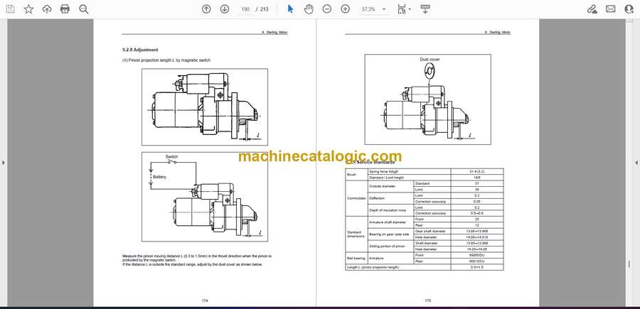
9.2.8 Adjustment ……………………………………………………………………………………………………………174
9.2.9 Service standards…………………………………………………………………………………………………..175


