Mitsubishi S16R-Y1PTA-2 Diesel Engine Service Manual (TP6527)
These S16R-Y1PTA engines usually sit in generator sets or heavy industrial installations, running long hours in hot, dusty, or coastal environments. This service manual is what I’d keep open when I’m tracing a hard-start issue, chasing low power under load, or confirming wear before tearing into a major component. It walks you through how to isolate a fault step by step, so you’re replacing the right parts instead of just guessing—like when you’re deciding if a misfire is fuel-system related or coming from valve or injector timing problems.
Applications & Use Cases
- Systematic troubleshooting of starting, smoke, or power complaints before authorizing major repairs.
- Guided disassembly/assembly so you can strip and rebuild subassemblies without missing seals, shims, or alignment steps.
- Adjustment checks for things like linkages and timing to verify settings before blaming a failed component.
- Root-cause verification after a failure, helping you trace what actually caused the damage.
- Parts identification aid when you’re matching what’s on the engine to what you need to order.
FAQ
Q: Can I use this on a tablet at the genset?
A: Yes, it’s practical on a tablet; you can zoom diagrams and keep your hands free at the engine.
Q: Is it worth printing sections of this manual?
A: For messy jobs, printing just the relevant procedures keeps your tablet clean and lets you mark notes as you work.
Safety Note
Always lock out the generator set and verify zero energy state before opening or adjusting any part of the engine.
Mitsubishi S16R-Y1PTA-2 Diesel Index:
- BINDING
- INTRODUCTION
- How to Use This Manual
- Methods of Indication
- Terms Used in This Manual
- Abbreviations, Standards, Etc.
- Units of Measurement
- Safety Cautions
- Warning Fire and Explosion
- Keep flames away
- Keep engine and surrounding area clean
- Never open crankcase until engine cools
- Check for fuel, oil and exhaust gas leaks
- Use flameproof light
- Do not short electrical wires
- Keep fire extinguishers and first-aid kit nearby
- Warning Stay Clear of All Rotating and Moving Parts
- Install protective covers on rotating parts
- Check surrounding area for safety
- Stay clear of all rotating and moving parts while engine is operating
- Lockout and Tagout
- Always stop engine before inspection and maintenance
- Always return turning tools to original position
- Warning Be Careful of Burns
- Do not touch engine during operation or immediately after operation
- Open radiator filler cap carefully
- Add coolant only after coolant temperature drops
- Do not dismount heat protection covers
- Warning Be Careful of Exhaust Fume Poisoning
- Perform engine operation in a well-ventilated site
- Warning Protect Ears from Noises
- Warning Be Careful of Falling Down
- Lifting engine carefully
- Do not climb onto engine
- Always prepare steady platform
- Caution Be Careful of Handling Fuel, Engine Oil and LLC
- Use only specified fuel, engine oil and coolant (LLC)
- Handle LLC carefully
- Properly dispose of drained oil and LLC
- Caution Service Battery
- Caution When Abnormality Occurs
- If engine overheats, conduct cooling operation before stopping engine
- If engine stops due to abnormality, exercise caution when restarting
- If engine oil pressure drops, stop engine immediately
- If fan belt is broken off, stop engine immediately
- Caution Other Cautions
- Never modify engine
- Never break seals
- Everyday checkup and periodic inspection and maintenance
- Perform engine break-in
- Warm up engine before use
- Never operate engine under overload condition
- Conduct cooling operation before stopping engine
- Do not splash water on engine
- Conduct proper maintenance of air cleaner/ pre-cleaner
- Observe safety rules at workplace
- Wear proper work clothes and protective gear
- Use appropriate tools for maintenance work
- Do not use starter continuously
- Keep battery switch ON when engine is in operation
- Cautions concerning transportation
- Do not operate engine continuously under low load
- Ventilate the engine room sufficiently
- Do not touch high-pressure injection fuel
- Caution About Warning Labels
- Always keep warning labels clean and legible
- GENERAL CONTENTS
- GENERAL
- 1. Outline
- 1.1 External view
- 1.2 Outline of fuel system
- 1.3 Outline of lubrication system
- 1.4 Outline of cooling system
- 1.5 Outline of inlet and exhaust system
- 1.6 Outline of electrical system
- 1.7 Engine serial number location
- 1.8 Engine model code identification
- 2. Main specification
- 3. Tips on disassembling and reassembling
- 3.1 Disassembling
- 3.2 Reassembling
- MAINTENANCE STANDARDS
- 1. Maintenance standard table
- 1.1 General
- 1.2 Engine main part
- 1.3 Inlet and exhaust system
- 1.4 Fuel system
- 1.5 Lubrication system
- 1.6 Cooling system
- 1.7 Electrical system
- 2. Tightening torque table
- 2.1 Major bolt and nut
- 2.1.1 Engine
- 2.1.2 Inlet and exhaust system
- 2.1.3 Fuel system
- 2.1.4 Lubrication system
- 2.1.5 Cooling system
- 2.1.6 Electrical system
- 2.2 Standard bolt and nut tightening torque
- 2.3 Standard eyebolt tightening torque
- 2.4 Standard union nut tightening torque
- 2.5 High-pressure fuel injection pipe tightening torque
- 3. Sealant and lubricant table
- 3.1 Engine main part
- 3.2 Lubrication system
- 3.3 Cooling system
- 3.4 Inlet system
- 3.5 Others
- BASIC AND SPECIAL TOOLS
- 1. Commercially-available tool
- 2. Special tool
- OVERHAUL INSTRUCTIONS
- 1. Determing overhaul timing
- 2. Testing compression pressure
- DISASSEMBLY OF ENGINE MAIN PARTS
- 1. Disassembling cylinder head and valve mechanism
- 1.1 Removing nozzle assembly
- 1.2 Removing rocker arm assembly and push rod
- 1.3 Removing rocker assembly
- 1.4 Removing valve bridge
- 1.5 Removing rocker case
- 1.6 Removing cylinder head assembly
- 1.7 Removing valve and valve spring
- 2. Disassembling flywheel, timing gear, camshaft
- 2.1 Removing flywheel
- 2.2 Removing idler shaft thrust collar
- 2.3 Removing timing gear case
- 2.4 Measuring timing gear backlash and end play
- 2.5 Removing accessory drive (right and left)
- 2.6 Removing idler gear
- 2.7 Removing idler shaft
- 2.8 Removing camshaft gear
- 2.9 Removing camshaft
- 3. Disassembling damper and front gear
- 3.1 Removing damper
- 3.2 Removing mounting plate for oil pump and water pump
- 3.3 Removing oil pump gear
- 3.4 Removing fan drive case
- 3.5 Removing front gear case
- 3.6 Removing bearing cover for oil pump and water pump
- 3.7 Measuring idler gear backlash and end play
- 3.8 Removing idler gear on the front side
- 3.9 Removing idler shaft on the front side
- 4. Disassembling cylinder liner, piston and connecting rod
- 4.1 Removing connecting rod cap
- 4.2 Removing carbon deposits at the upper section of cylinder liner
- 4.3 Removing piston
- 4.4 Removing piston ring
- 4.5 Removing piston pin and piston
- 5. Disassembling crankcase, crankshaft and main bearing
- 5.1 Reversing crankcase
- 5.2 Removing main bearing cap
- 5.3 Removing crankshaft
- 5.4 Removing piston cooling nozzle
- INSPECTION AND REPAIR OF ENGINE MAIN PARTS
- 1. Cylinder head and valve mechanism
- 1.1 Measuring rocker arm inside diameter and rocker shaft outside diameter
- 1.2 Replacing rocker bushing
- 1.3 Measuring rocker inside diameter and rocker shaft diameter
- 1.4 Replacing valve guide and stem seal
- 1.5 Inspecting valve face
- 1.6 Correcting valve face
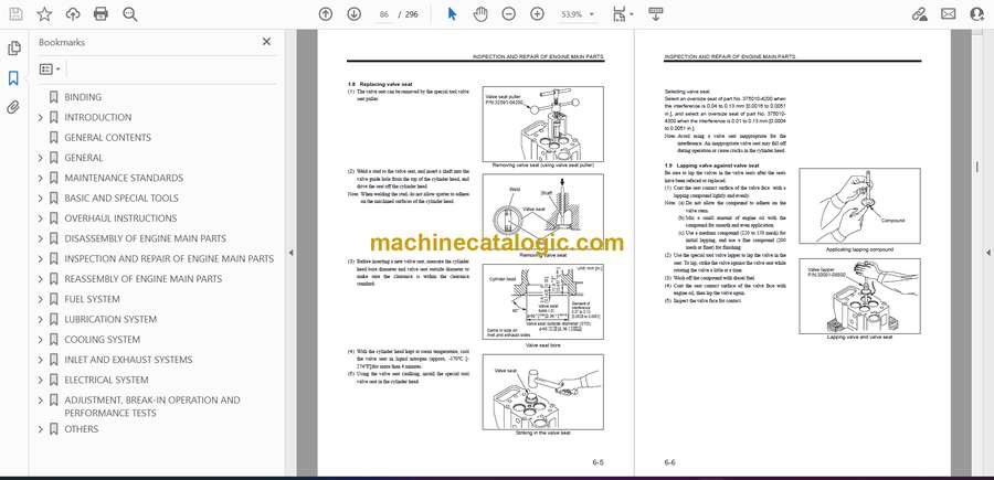
- 1.7 Correcting valve seat
- 1.8 Replacing valve seat
- 1.9 Lapping valve against valve seat
- 1.10 Measuring valve spring perpendicularity and free length
- 1.11 Inspecting clearance between valve bridge with valve cotter and valve rotator
- 1.12 Inspecting tappet
- 1.13 Measuring push rod bend
- 1.14 Measuring cylinder head bottom face for distortion
- 2. Cylinder liner, piston and connecting rod
- 2.1 Measuring cylinder liner bore diameter
- 2.2 Measuring cylinder liner collar protrusion
- 2.2.1 When cylinder liner is not to be replaced
- 2.2.2 When cylinder liner is to be replaced
- 2.2.3 Measuring step height of cylinder liner
- 2.2.4 Inserting cylinder liner shim
- 2.3 Replacing cylinder liner
- 2.4 Inspecting piston exterior
- 2.5 Measuring piston outside diameter
- 2.6 Inspecting piston ring groove
- 2.7 Measuring piston pin bore diameter
- 2.8 Measuring piston protrusion
- 2.9 Measuring piston ring end gap
- 2.10 Measuring piston pin diameter
- 2.11 Measuring connecting rod bushing inside diameter
- 2.12 Replacing connecting rod bushing
- 2.13 Inspecting connecting rod bend and twist
- 2.14 Inspecting connecting rod bearing
- 2.15 Measuring connecting rod end play
- 2.16 Weight difference of connecting rods in one engine
- 2.17 Measuring connecting rod big-end bore diameter and circularity
- 2.18 Inspecting connecting rod big-end bore serration
- 2.19 Measuring connecting rod bearing thickness
- 3. Damper and front gear
- 3.1 Inspecting damper
- 3.2 Measuring front gear backlash
- 3.3 Inside and outside fitting surface conditioning oil pump gear bearing
- 3.4 Measuring idler bushing inside diameter and idler shaft diameter
- 3.5 Measuring idler gear end play
- 3.6 Replacing idler bushing
- 4. Flywheel, timing gear and camshaft
- 4.1 Measuring face and radial runout of flywheel
- 4.2 Measuring timing gear backlash
- 4.3 Measuring idler bushing inside diameter and idler shaft diameter
- 4.4 Measuring idler gear end play
- 4.5 Replacing idler bushing
- 4.6 Measuring camshaft cam height
- 4.7 Measuring camshaft deflection
- 4.8 Measuring camshaft journal diameter
- 4.9 Measuring camshaft bushing inside diameter
- 4.10 Measuring camshaft end play
- 4.11 Replacing camshaft bushing
- 4.11.1 Removing camshaft bushing
- 4.11.2 Installing camshaft bushing
- 5. Crankcase, crankshaft and main bearing
- 5.1 Measuring crankshaft crankpin and journal diameter
- 5.2 Grinding crankshaft
- 5.3 Crankshaft end play
- 5.4 Measuring crankshaft deflection
- 5.5 Replacing oil seal slinger
- 5.5.1 Removing oil seal slinger
- 5.5.2 Installing oil seal slinger
- 5.6 Replacing crankshaft gear
- 5.6.1 Removing crankshaft gear
- 5.6.2 Installing crankshaft gear
- 5.7 Inspecting main bearing surface
- 5.8 Measuring main bearing thickness
- 5.9 Replacing main bearing
- 5.10 Measuring crankcase gasket surface distortion
- 5.11 Measuring main bearing bore diameter
- REASSEMBLY OF ENGINE MAIN PARTS
- 1. Reassembling crankcase,crankshaft and main bearing
- 1.1 Installing main bearing
- 1.2 Installing thrust plate
- 1.3 Installing crankshaft
- 1.4 Installing main bearing cap
- 1.5 Installing main bearing cap bolt
- 1.6 Measuring crankshaft end play
- 2. Reassembling cylinder liner, piston and connecting rod
- 2.1 Reassembling piston and connecting rod
- 2.2 Installing piston ring
- 2.3 Preparation for installing piston
- 2.4 Installing connecting rod bearing upper half
- 2.5 Installing piston
- 2.6 Installing connecting rod cap
- 3. Reassembling damper and front gear
- 3.1 Installing front plate
- 3.2 Installing idler shaft
- 3.3 Installing idler gear
- 3.4 Installing oil pump and water pump drive bearing cover
- 3.5 Installing front gear case and pointer
- 3.6 Installing oil pump gear and oil pump/water pump mounting plate
- 3.7 Installing damper
- 4. Reassembling flywheel, timing gear, camshaft, oil pan
- 4.1 Installing rear plate
- 4.2 Turning engine
- 4.3 Installing idler shaft
- 4.4 Installing camshaft
- 4.5 Installing camshaft gear
- 4.6 Installing idler gear
- 4.7 Installing fuel injection pump accessory drive (right-and- left side)
- 4.8 Inspecting and adjusting timing gear after installation
- 4.8.1 Inspecting backlash and end play
- 4.8.2 Inspecting valve timing
- 4.9 Installing timing gear case
- 4.10 Installing rear oil seal
- 4.11 Installing idler shaft thrust collar
- 4.12 Installing flywheel
- 4.13 Installing pickup
- 4.14 Installing oil pan
- 5. Reassembling cylinder head and valve mechanism
- 5.1 Installing inlet and exhaust valve
- 5.2 Installing tappet
- 5.3 Applicating liquid gasket
- 5.4 Installing cylinder head gasket
- 5.5 Installing cylinder head assembly
- 5.6 Tightening cylinder head bolt
- 5.6.1 2-step tightening method
- 5.6.2 Angle tightening method
- 5.7 Installing rocker case
- 5.8 Installing bridge and bridge cap
- 5.9 Installing rocker shaft assembly
- 5.10 Installing fuel injection nozzle assembly
- 5.11 Adjusting valve clearance
- FUEL SYSTEM
- 1. Removing fuel system
- 1.1 Removing and inspecting fuel injection pipe and fuel leak-off pipe
- 1.2 Removing and inspecting fuel filter and fuel pipe
- 1.3 Removing and inspecting fuel control link
- 1.4 Removing and inspecting actuator
- 1.5 Removing and inspecting stop solenoid
- 1.6 Removing fuel injection pump
- 2. Removing, inspecting and assembling fuel system
- 2.1 Removing and inspecting fuel filter
- 2.2 Fuel filter assembly
- 2.3 Disassembling and inspecting fuel injection nozzle
- 2.4 Inspecting and adjusting fuel injection start pressure
- 2.5 Inspecting fuel injection nozzle spray condition
- 2.6 Cleaning and exchange at defective injection
- 2.6.1 Removing nozzle tip
- 2.6.2 Cleaning and mounting nozzle tip
- 2.7 Reassembling fuel injection nozzle
- 2.8 Disassembling and inspecting fuel injection pump
- 2.8.1 Preparing fuel injection pump disassembly
- 2.8.2 Disassembling rack set cap
- 2.8.3 Disassembling spring case
- 2.8.4 Disassembling return spring
- 2.8.5 Disassembling coupling assembly and fuel feed pump
- 2.8.6 Disassembling delivery valve
- 2.8.7 Disassembling plunger assembly
- 2.8.8 Disassembling controller rack
- 2.8.9 Disassembling tappet
- 2.8.10 Disassembling camshaft
- 2.8.11 Disassembling rear cover
- 2.8.12 Disassembling plunger assembly
- 2.9 Inspecting fuel injection pump
- 2.9.1 Inspecting plunger barrel
- 2.9.2 Inspecting delivery valve
- 2.9.3 Inspecting tappet
- 2.9.4 Inspecting bearing
- 2.9.5 Inspecting valve holder
- 2.9.6 Inspecting pump case
- 2.9.7 O-ring and bellow on each unit
- 2.9.8 Inspecting camshaft
- 2.9.9 Inserting oversize sleeve to camshaft
- 2.9.10 Inspecting plunger spring and delivery valve spring
- 2.10 Reassembling fuel injection pump
- 2.10.1 Installing bearing and front cover
- 2.10.2 Installing camshaft and center bearing
- 2.10.3 Installing rear cover
- 2.10.4 Measuring thrust clearance of camshaft
- 2.10.5 Installing tappet roller assembly
- 2.10.6 Installing tappet
- 2.10.7 Reassembling plunger assembly
- 2.10.8 Installing controller rack
- 2.10.9 Positional relationship between plunger and barrel
- 2.10.10 Reassembling plunger assembly
- 2.10.11 Measuring control rack sliding resistance
- 2.10.12 Reassembling delivery valve
- 2.10.13 Reassembling bellow
- 2.10.14 Reassembling fuel feed pump
- 2.10.15 Reassembling flywheel
- 2.10.16 Reassembling coupling assembly
- 2.10.17 Reassembling controller rack return spring
- 2.11 Adjusting fuel injection pump
- 2.11.1 Adjusting pre-stroke (injection timing)
- 2.11.2 Adjusting injection interval
- 2.11.3 Adjusting injection volume
- 2.12 Disassembling and inspecting fuel feed pump
- 2.13 Reassembling fuel feed pump
- 2.13.1 Tightening priming cap
- 2.14 Fuel feed pump test
- 2.14.1 Fuel feed pump air-tightness test
- 2.14.2 Fuel feed pump fuel feeding pressure test
- 2.14.3 Priming pump suction capacity test
- 2.14.4 Fuel feed pump fuel feed rate test
- 2.15 Disassembling and inspecting fuel injection pump accessory drive
- 2.16 Inspecting outer and inner diameters of fuel injection pump accessory drive bearing engagement section
- 2.17 Reassembling fuel injection pump accessory drive
- 3. Installing fuel system
- 3.1 Installing fuel injection pump
- 3.1.1 Fuel injection timing check
- 3.1.2 Reassembling coupling on driving side
- 3.1.3 Checking before assembly fuel injection pump
- 3.1.4 Reassembling fuel injection pump
- 3.1.5 Adjusting clearance of flywheel and coupling
- 3.1.6 Assembling fuel injection pump (left)
- 3.2 Installing stop solenoid
- 3.3 Installing actuator
- 3.3.1 Installing and adjusting actuator link
- 3.4 Adjusting and confirming working of stop solenoid
- 3.4.1 Adjusting stop solenoid
- 3.4.2 Stop solenoid working inspection
- 3.5 Re-adjusting adjusting bolt
- 3.6 Installing fuel control link
- 3.7 Installing fuel filter and fuel pipe
- 3.8 Installing fuel injection pipe and fuel leak pipe
- 3.9 Installing pickup
- LUBRICATION SYSTEM
- 1. Removing lubrication system
- 1.1 Removing oil cooler and oil pipes for fuel injection pump
- 1.2 Removing oil pump, oil filter and oil pan
- 2. Disassembling, inspecting and reassembling lubrication system
- 2.1 Disassembling and inspecting oil pump and safety valve
- 2.2 Inspecting oil pump and safety valve
- 2.2.1 Measuring of backlash between drive and driven gears
- 2.2.2 Measuring radical clearance between gear and case
- 2.2.3 Measuring side clearance between gear and case
- 2.2.4 Measuring drive and driven gear shaft diameters and bushing inside diameter
- 2.2.5 Checking oil pump safety valve spring
- 2.3 Reassembling oil pump and safety valve
- 2.4 Disassembling and inspecting oil filter, oil filter alarm, relief valve, left-side oil cooler and oil thermostat
- 2.5 Inspecting oil filter, oil filter alarm, relief valve, left-side oil cooler and oil thermostat
- 2.5.1 Inspecting oil filter
- 2.5.2 Inspecting oil filter alarm
- 2.5.3 Measuring relief valve pressure
- 2.5.4 Checking oil cooler
- 2.5.5 Inspecting oil thermostat
- 2.5.6 Reassembling oil filter, oil filter alarm, relief valve, left-hand oil cooler and oil thermostat
- 2.6 Disassembling and inspecting right-side oil cooler and oil thermostat
- 2.7 Inspecting right-side oil cooler and oil thermostat
- 2.8 Reassembling oil cooler and oil thermostat
- 3. Installing lubrication system
- 3.1 Installing oil pump, oil filter and oil pan
- 3.2 Installing fuel injection pump oil pipes and oil cooler
- COOLING SYSTEM
- 1. Removing cooling system
- 1.1 Removing thermostat case and water pipe
- 1.2 Removing water pump
- 2. Disassembling, inspecting, and reassembling cooling system
- 2.1 Disassembling and inspecting water pump
- 2.1.1 Inspecting pump mounted on engine
- 2.1.2 Removing impeller
- 2.1.3 Removing water pump gear
- 2.2 Inspecting water pump
- 2.3 Reassembling water pump
- 2.3.1 Installing water pump oil seal
- 2.3.2 Installing unit seal
- 2.3.3 Striking in impeller side ball bearing
- 2.3.4 Reassembling unit seal ring
- 2.3.5 Striking in nut side ball bearing
- 2.3.6 Press-fitting water pump impeller
- 2.3.7 Installing water pump pulley
- 2.4 Disassembling thermostat
- 2.5 Inspecting water thermostat
- 2.6 Disassembling and inspecting fan drive
- 2.7 Inspecting fan drive
- 3. Installing cooling system
- 3.1 Installing water pump
- 3.2 Installing thermostat case and water pipe
- 3.3 Installing fan drive
- 3.3.1 Installing bearing
- 3.3.2 Installing drive shaft
- 3.3.3 Installing fan drive gear
- 3.3.4 Installing fan
- INLET AND EXHAUST SYSTEMS
- 1. Air duct (Air cooler-to-turbocharger)
- 1.1 Disassembling and inspecting air duct
- 1.2 Reassembling air duct
- 2. Insulator
- 2.1 Disassembling and inspecting insulator
- 2.2 Reassembling insulator
- 3. Exhaust manifold
- 3.1 Disassembling and inspecting exhaust manifold
- 3.2 Reassembing exhaust manifold
- 4. Turbocharger oil pipe
- 4.1 Disassembling and inspecting turbocharger oil pipe
- 4.2 Reassembing turbocharger oil pipe
- 5. Exhaust pipe
- 5.1 Disassembling and inspecting exhaust pipe
- 5.2 Reassembling exhaust pipe
- 6. Air duct (Air cooler-to-crankcase)
- 6.1 Disassembling and inspecting air duct
- 6.2 Reassembling air duct
- 7. Turbocharger
- 7.1 Disassembling and inspecting turbocharger
- 7.1.1 Removing turbine housing
- 7.1.2 Removing compressor cover
- 7.1.3 Removing compressor wheel
- 7.1.4 Removing snap ring
- 7.1.5 Removing insert and oil deflector
- 7.1.6 Removing V-clamp
- 7.1.7 Removing shaft & turbine wheel
- 7.1.8 Removing snap ring and bearing
- 7.2 Cleaning
- 7.3 Inspecting turbocharger
- 7.3.1 Bearing housing
- 7.3.2 Bearing
- 7.3.3 Shaft & turbine wheel
- 7.3.4 Insert Measuring piston ring end gap
- 7.4 Reassembling turbocharger
- 7.4.1 Installing shaft & turbine wheel and bearing
- 7.4.2 Installing thrust bearing
- 7.4.3 Installing O-ring
- 7.4.4 Installing oil deflector
- 7.4.5 Reassembling insert sub-assembly
- 7.4.6 Installing snap ring
- 7.4.7 Measuring clearance between turbine wheel and turbine housing
- 7.4.8 Installing compressor wheel
- 7.4.9 Measuring play of shaft & turbine wheel in axial direction
- 7.4.10 Measuring clearance between turbine backplate and back side of turbine wheel
- 7.4.11 Installing compressor cover
- 7.4.12 Installing lock plate
- 7.4.13 Installing turbine housing
- 7.4.14 Tightening turbine housing V-clamp
- ELECTRICAL SYSTEM
- 1. Removing electrical system
- 1.1 Removing starter
- 1.2 Inspecting before removing alternator
- 1.2.1 Checking alternator operation
- 1.2.2 Handling precaution
- 1.3 Removing alternator
- 2. Inspecting and reassembling electrical system
- 2.1 Disassembling and inspecting starter
- 2.1.1 Removing magnetic switch
- 2.1.2 Removing rear bracket
- 2.1.3 Removing armature and yoke assembly
- 2.1.4 Removing center bracket
- 2.1.5 Removing pinion set
- 2.2 Inspecting and correcting starter
- 2.2.1 Testing magnetic switch coil
- 2.2.2 Testing magnetic switch contact point
- 2.2.3 Measuring armature shaft runout
- 2.2.4 Inspecting commutator radial runout
- 2.2.5 Measuring commutator undercut
- 2.2.6 Measuring commutator outside diameter
- 2.2.7 Checking armature coil
- 2.2.8 Checking field coil for open circuit
- 2.2.9 Inspecting overrunning clutch
- 2.2.10 Inspecting brushes for wear
- 2.2.11 Measuring brush spring load
- 2.2.12 Inspecting safety switch
- 2.3 Reassembling starter
- 2.3.1 Installing pinion shaft
- 2.3.2 Installing shift lever and pinion shaft
- 2.3.3 Installing armature, yoke, brushes and holder
- 2.3.4 Installing rear bracket
- 2.3.5 Measuring armature end play
- 2.3.6 Measuring pinion shaft end play
- 2.3.7 Measuring pinion gear retraction length
- 2.3.8 Installing magnetic switch
- 2.4 Disassembling and inspecting alternator
- 2.4.1 Separating front bracket from stator
- 2.4.2 Removing pulley
- 2.4.3 Removing rear bearing
- 2.4.4 Removing front bearing
- 2.4.5 Removing stator
- 2.4.6 Removing regulator assembly
- 2.4.7 Removing rectifier assembly
- 2.5 Inspecting and repairing alternator
- 2.5.1 Checking rectifier
- 2.5.2 Checking field coil
- 2.5.3 Checking stator
- 2.5.4 Inspecting brushes for wear
- 2.5.5 Replacing brushes
- 2.6 Reassembling alternator
- 2.6.1 Installing rectifier assembly and regulator assembly
- 2.6.2 Installing stator
- 2.6.3 Installing front bearing
- 2.6.4 Installing rear bearing
- 2.6.5 Installing pulley
- 2.6.6 Assembling stator and front bracket
- 3. Reinstalling electrical system
- 3.1 Installing starter
- 3.2 Installing alternator
- ADJUSTMENT, BREAK-IN OPERATION AND PERFORMANCE TESTS
- 1. Adjusting engine
- 1.1 Inspecting and adjusting valve clearance
- 1.1.1 Checking clearance between bridge and valve rotator
- 1.1.2 Using turning gear
- 1.1.3 Inspecting valve clearance
- 1.1.4 Adjusting front and rear valve heights by valve bridge
- 1.1.5 Adjusting valve clearance
- 1.2 Bleeding fuel system
- 1.2.1 Bleeding fuel filter
- 1.2.2 Bleeding fuel injection pump
- 1.2.3 Tightening priming pump cap
- 1.3 Inspecting and adjusting fuel injection timing (right side)
- 1.3.1 Injection timing and its indication location
- 1.3.2 Checking No. 1 cylinder top dead center in compression stroke
- 1.3.3 Inspecting fuel injection timing
- 1.3.4 Adjusting fuel injection timing
- 1.4 Adjusting no-load minimum engine speed (idling) and no-load maximum engine speed
- 1.5 Inspecting and adjusting tension of alternator drive belt
- 2. Break-in operation
- 2.1 Starting up
- 2.2 Inspecting during break-in operation
- 2.3 Break-in duration
- 2.4 Inspecting and adjusting after break-in operation
- 3. Performance test (JIS standard)
- 3.1 Engine equipment condition
- 3.2 Test items and purposes
- 3.2.1 Operation load test
- 3.2.2 Continuous load test
- 3.2.3 Low idel test
- 3.3 Other inspections
- 3.4 Engine output adjustment
- 3.4.1 Standard atmospheric conditions:
- 3.4.2 Calculation of corrected power
- OTHERS
- 1. Dissassembling and reassembling general part
- 1.1 Oil seal
- 1.1.1 Installing oil seal to housing
- 1.1.2 Installing oil seal to shaft
- 1.2 O-ring
- 1.3 Bearing
- 1.4 Lock plate
- 1.5 Split pins and spring pin
Kohler


