Format: PDF (Printable Document)
File Language: English
File Pages: 192
File Size: 90.09 MB (Speed Download Link)
Brand: Kohler
Model: KSS, KSP, KGS, KGP Automatic Transfer Switches
Book No: tp6921
Type of Document: Service Manual
$ 40
These Kohler KSS/KSP/KGS/KGP automatic transfer switches usually sit in plant rooms, data centers, or commercial buildings, quietly handling the swap between utility and generator power. This service manual is what I’d pull out when the switch hesitates to transfer, chatters, or won’t return to normal after the mains come back. It walks you through how to trace control signals, verify mechanical movement, and confirm a real component failure before you start ordering expensive parts.
Applications & Use Cases
FAQ
Q: Can I use this manual on a tablet or phone in the field?
A: Yes, it’s practical to keep a digital copy, then zoom into diagrams while you’re standing at the switchgear.
Q: Should I still print parts of it?
A: Many techs print the key procedures or diagrams they use often to avoid handling devices in tight or dirty switch rooms.
Safety Note
Always isolate all power sources and verify absence of voltage before opening or working inside an automatic transfer switch.
Safety Precautions and Instructions . . . . . . . . . . . . . . . . . . . . . . . . . . . . . . . . . . . . . . . . . . . . . . . . . . . . . . . . . 7
Introduction . . . . . . . . . . . . . . . . . . . . . . . . . . . . . . . . . . . . . . . . . . . . . . . . . . . . . . . . . . . . . . . . . . . . . . . . . . . . . . . 11
List of Related Materials . . . . . . . . . . . . . . . . . . . . . . . . . . . . . . . . . . . . . . . . . . . . . . . . . . . . . . 11
Service Assistance . . . . . . . . . . . . . . . . . . . . . . . . . . . . . . . . . . . . . . . . . . . . . . . . . . . . . . . . . . . . . . . . . . . . . . . . . 12
Section 1 Sequence of Operation . . . . . . . . . . . . . . . . . . . . . . . . . . . . . . . . . . . . . . . . . . . . . . . . . . . . . . . . . . . 13
1.1 Controller Power-up/Reset . . . . . . . . . . . . . . . . . . . . . . . . . . . . . . . . . . . . . . . . . . . . . . 13
1.2 Sequence of Operation, MPAC 750 Controller . . . . . . . . . . . . . . . . . . . . . . . . . . . . . 13
1.2.1 Source N Loss and Return . . . . . . . . . . . . . . . . . . . . . . . . . . . . . . . . . . . . . . 13
1.2.2 Exerciser Operation . . . . . . . . . . . . . . . . . . . . . . . . . . . . . . . . . . . . . . . . . . . . 13
1.2.3 Test Sequence . . . . . . . . . . . . . . . . . . . . . . . . . . . . . . . . . . . . . . . . . . . . . . . . 14
1.3 Sequence of Operation, MPAC 1200 and 1500, Standard Transition . . . . . . . . . . 15
1.3.1 Preferred Source Loss and Return, Standard Transition . . . . . . . . . . . . . 15
1.3.2 Exerciser Operation, Standard Transition . . . . . . . . . . . . . . . . . . . . . . . . . 15
1.3.3 Test Sequence, Standard Transition . . . . . . . . . . . . . . . . . . . . . . . . . . . . . . 16
1.4 Sequence of Operation, MPAC 1200 and 1500, Programmed-Transition . . . . . . 17
1.4.1 Preferred Source Loss and Return, Programmed Transition . . . . . . . . . 17
1.4.2 Exerciser Operation, Programmed Transition . . . . . . . . . . . . . . . . . . . . . . 17
1.4.3 Test Sequence, Programmed Transition . . . . . . . . . . . . . . . . . . . . . . . . . . 18
Section 2 Scheduled Maintenance . . . . . . . . . . . . . . . . . . . . . . . . . . . . . . . . . . . . . . . . . . . . . . . . . . . . . . . . . . 19
2.1 Introduction . . . . . . . . . . . . . . . . . . . . . . . . . . . . . . . . . . . . . . . . . . . . . . . . . . . . . . . . . . . 19
2.2 Inspection and Service . . . . . . . . . . . . . . . . . . . . . . . . . . . . . . . . . . . . . . . . . . . . . . . . . 20
2.2.1 General Inspection . . . . . . . . . . . . . . . . . . . . . . . . . . . . . . . . . . . . . . . . . . . . . 20
2.2.2 Internal Inspections and Maintenance . . . . . . . . . . . . . . . . . . . . . . . . . . . . 20
2.2.3 Model KGS/KGP Bypass/Isolation Switches . . . . . . . . . . . . . . . . . . . . . . . 22
2.3 Testing . . . . . . . . . . . . . . . . . . . . . . . . . . . . . . . . . . . . . . . . . . . . . . . . . . . . . . . . . . . . . . . 23
2.3.1 Weekly Generator Set Exercise . . . . . . . . . . . . . . . . . . . . . . . . . . . . . . . . . . 23
2.3.2 Monthly Automatic Operation Test . . . . . . . . . . . . . . . . . . . . . . . . . . . . . . . 23
2.3.3 Other Tests . . . . . . . . . . . . . . . . . . . . . . . . . . . . . . . . . . . . . . . . . . . . . . . . . . . 23
2.4 View Maintenance Records . . . . . . . . . . . . . . . . . . . . . . . . . . . . . . . . . . . . . . . . . . . . . 25
2.5 Service Schedule . . . . . . . . . . . . . . . . . . . . . . . . . . . . . . . . . . . . . . . . . . . . . . . . . . . . . . 25
Section 3 SiteTech Software . . . . . . . . . . . . . . . . . . . . . . . . . . . . . . . . . . . . . . . . . . . . . . . . . . . . . . . . . . . . . . . . 27
3.1 Connection . . . . . . . . . . . . . . . . . . . . . . . . . . . . . . . . . . . . . . . . . . . . . . . . . . . . . . . . . . . 27
3.2 Using SiteTech . . . . . . . . . . . . . . . . . . . . . . . . . . . . . . . . . . . . . . . . . . . . . . . . . . . . . . . . 27
3.2.1 Changing Settings . . . . . . . . . . . . . . . . . . . . . . . . . . . . . . . . . . . . . . . . . . . . . 27
3.2.2 Update Firmware . . . . . . . . . . . . . . . . . . . . . . . . . . . . . . . . . . . . . . . . . . . . . . 28
3.3 Exporting and Importing Parameter Settings . . . . . . . . . . . . . . . . . . . . . . . . . . . . . . . 29
3.3.1 Export Parameters . . . . . . . . . . . . . . . . . . . . . . . . . . . . . . . . . . . . . . . . . . . . . 29
3.3.2 Editing Parameter Files . . . . . . . . . . . . . . . . . . . . . . . . . . . . . . . . . . . . . . . . . 30
3.3.3 Import Parameters . . . . . . . . . . . . . . . . . . . . . . . . . . . . . . . . . . . . . . . . . . . . . 30
3.4 Parameters . . . . . . . . . . . . . . . . . . . . . . . . . . . . . . . . . . . . . . . . . . . . . . . . . . . . . . . . . . . 32
3.5 Calibration . . . . . . . . . . . . . . . . . . . . . . . . . . . . . . . . . . . . . . . . . . . . . . . . . . . . . . . . . . . . 40
Section 4 Troubleshooting . . . . . . . . . . . . . . . . . . . . . . . . . . . . . . . . . . . . . . . . . . . . . . . . . . . . . . . . . . . . . . . . . 41
4.1 Initial Checks . . . . . . . . . . . . . . . . . . . . . . . . . . . . . . . . . . . . . . . . . . . . . . . . . . . . . . . . . . 41
4.2 Check for Loose Connections . . . . . . . . . . . . . . . . . . . . . . . . . . . . . . . . . . . . . . . . . . . 42
4.3 View Event History . . . . . . . . . . . . . . . . . . . . . . . . . . . . . . . . . . . . . . . . . . . . . . . . . . . . . 42
4.4 System Power . . . . . . . . . . . . . . . . . . . . . . . . . . . . . . . . . . . . . . . . . . . . . . . . . . . . . . . . . 43
4.4.1 Controller Display is OFF . . . . . . . . . . . . . . . . . . . . . . . . . . . . . . . . . . . . . . . 43
4.4.2 Generator is Not Running . . . . . . . . . . . . . . . . . . . . . . . . . . . . . . . . . . . . . . . 43
4.4.3 Source Voltage, Frequency, and Phase Rotation Checks . . . . . . . . . . . . 44
4.5 System Settings . . . . . . . . . . . . . . . . . . . . . . . . . . . . . . . . . . . . . . . . . . . . . . . . . . . . . . . 45
4.5.1 Controller Source Settings . . . . . . . . . . . . . . . . . . . . . . . . . . . . . . . . . . . . . . 45
4.5.2 Voltage and Frequency Pickup and Dropout Settings . . . . . . . . . . . . . . . 46
Table of Contents, continued
Table of Contents TP-6921 10/14
4.6 Time Delays . . . . . . . . . . . . . . . . . . . . . . . . . . . . . . . . . . . . . . . . . . . . . . . . . . . . . . . . . . 47
4.7 Reset Data, MPAC 1200 and 1500 . . . . . . . . . . . . . . . . . . . . . . . . . . . . . . . . . . . . . . . 48
4.7.1 Reset Maintenance Records . . . . . . . . . . . . . . . . . . . . . . . . . . . . . . . . . . . . 48
4.7.2 Reset Event History . . . . . . . . . . . . . . . . . . . . . . . . . . . . . . . . . . . . . . . . . . . . 48
4.7.3 Reset Default Parameters . . . . . . . . . . . . . . . . . . . . . . . . . . . . . . . . . . . . . . 48
4.7.4 Reset and Disable Test Password . . . . . . . . . . . . . . . . . . . . . . . . . . . . . . . . 48
4.7.5 Reset Data Procedure, MPAC 1200 and MPAC 1500 . . . . . . . . . . . . . . . 49
4.8 Controller Reset, MPAC 750 . . . . . . . . . . . . . . . . . . . . . . . . . . . . . . . . . . . . . . . . . . . . 49
4.9 Warnings and Faults . . . . . . . . . . . . . . . . . . . . . . . . . . . . . . . . . . . . . . . . . . . . . . . . . . . 49
4.9.1 Fault Reset, MPAC 1200 and 1500 Controllers . . . . . . . . . . . . . . . . . . . . 51
4.9.2 Fault Reset, MPAC 750 Controller . . . . . . . . . . . . . . . . . . . . . . . . . . . . . . . 51
4.10 Accessory Module Faults . . . . . . . . . . . . . . . . . . . . . . . . . . . . . . . . . . . . . . . . . . . . . . . 51
4.10.1 Module Status Change . . . . . . . . . . . . . . . . . . . . . . . . . . . . . . . . . . . . . . . . . 51
4.10.2 Module Status Conflict . . . . . . . . . . . . . . . . . . . . . . . . . . . . . . . . . . . . . . . . . 53
4.11 Common Alarms . . . . . . . . . . . . . . . . . . . . . . . . . . . . . . . . . . . . . . . . . . . . . . . . . . . . . . . 53
4.12 Events and Faults Troubleshooting Table . . . . . . . . . . . . . . . . . . . . . . . . . . . . . . . . . 54
4.13 Transfer Switch Operation Troubleshooting Table . . . . . . . . . . . . . . . . . . . . . . . . . . 57
4.14 MPAC Controller Troubleshooting Flowcharts . . . . . . . . . . . . . . . . . . . . . . . . . . . . . . 62
4.14.1 MPAC 750 and 1200 Controllers for Models KSS/KSP . . . . . . . . . . . . . . 63
4.14.2 MPAC 1500 Controller for Models KGS/KGP . . . . . . . . . . . . . . . . . . . . . . 69
Section 5 Transfer Switch Testing . . . . . . . . . . . . . . . . . . . . . . . . . . . . . . . . . . . . . . . . . . . . . . . . . . . . . . . . . . . 75
5.1 Initial Checks . . . . . . . . . . . . . . . . . . . . . . . . . . . . . . . . . . . . . . . . . . . . . . . . . . . . . . . . . . 75
5.2 Contacts . . . . . . . . . . . . . . . . . . . . . . . . . . . . . . . . . . . . . . . . . . . . . . . . . . . . . . . . . . . . . . 75
5.3 Rectifier Test . . . . . . . . . . . . . . . . . . . . . . . . . . . . . . . . . . . . . . . . . . . . . . . . . . . . . . . . . . 75
5.4 Solenoid Tests . . . . . . . . . . . . . . . . . . . . . . . . . . . . . . . . . . . . . . . . . . . . . . . . . . . . . . . . 76
5.4.1 Solenoid Coil Resistance . . . . . . . . . . . . . . . . . . . . . . . . . . . . . . . . . . . . . . . 76
5.4.2 Solenoid Operation . . . . . . . . . . . . . . . . . . . . . . . . . . . . . . . . . . . . . . . . . . . . 76
5.4.3 Solenoid Operation Diagrams, 40–225 Amp Model KSS Standard
Transition Switches . . . . . . . . . . . . . . . . . . . . . . . . . . . . . . . . . . . . . . . . . . . . 77
5.4.4 Solenoid Operation Diagrams, 400–600 Amp Model KSS Standard
Transition Switches . . . . . . . . . . . . . . . . . . . . . . . . . . . . . . . . . . . . . . . . . . . . 78
5.4.5 Solenoid Operation Diagrams, 800–1000 Amp Model KSS Standard
Transition Switches . . . . . . . . . . . . . . . . . . . . . . . . . . . . . . . . . . . . . . . . . . . . 79
5.4.6 Solenoid Operation Diagrams, Model KSP Programmed-Transition
Models . . . . . . . . . . . . . . . . . . . . . . . . . . . . . . . . . . . . . . . . . . . . . . . . . . . . . . . 83
5.4.7 Solenoid Operation Diagrams, Model KGS Open Transition
Bypass/Isolation Switches . . . . . . . . . . . . . . . . . . . . . . . . . . . . . . . . . . . . . . 85
5.4.8 Solenoid Operation Diagrams, 150–400 Amp Model KGP
Programmed-Transition Bypass/Isolation Switches . . . . . . . . . . . . . . . . . 86
Solenoid Operation Diagrams, 150–400 Amp Model KGP
Programmed-Transition Bypass/Isolation Switches, continued . . . . . . . 87
5.4.9 Solenoid Operation Diagrams, 600–3000 Amp Model KGP
Programmed-Transition Bypass/Isolation Switches . . . . . . . . . . . . . . . . . 88
Solenoid Operation Diagrams, 600–3000 Amp Model KGP
Programmed-Transition Bypass/Isolation Switches, Continued . . . . . . . 89
Section 6 Controller Test and Replacement . . . . . . . . . . . . . . . . . . . . . . . . . . . . . . . . . . . . . . . . . . . . . . . . . . 91
6.1 User Interface Panel . . . . . . . . . . . . . . . . . . . . . . . . . . . . . . . . . . . . . . . . . . . . . . . . . . . 91
6.1.1 Display . . . . . . . . . . . . . . . . . . . . . . . . . . . . . . . . . . . . . . . . . . . . . . . . . . . . . . . 91
6.1.2 LED Indicators . . . . . . . . . . . . . . . . . . . . . . . . . . . . . . . . . . . . . . . . . . . . . . . . 92
6.1.3 Pushbuttons . . . . . . . . . . . . . . . . . . . . . . . . . . . . . . . . . . . . . . . . . . . . . . . . . . 93
6.1.4 Lamp Test . . . . . . . . . . . . . . . . . . . . . . . . . . . . . . . . . . . . . . . . . . . . . . . . . . . . 93
6.2 Controller Connections . . . . . . . . . . . . . . . . . . . . . . . . . . . . . . . . . . . . . . . . . . . . . . . . . 94
6.3 Controller Power . . . . . . . . . . . . . . . . . . . . . . . . . . . . . . . . . . . . . . . . . . . . . . . . . . . . . . . 95
6.3.1 Controller Disconnect Switch . . . . . . . . . . . . . . . . . . . . . . . . . . . . . . . . . . . . 95
6.3.2 Controller Power Supply . . . . . . . . . . . . . . . . . . . . . . . . . . . . . . . . . . . . . . . . 96
6.4 System Test, MPAC 1200 and 1500 Controllers . . . . . . . . . . . . . . . . . . . . . . . . . . . . 98
6.4.1 Unloaded System Test . . . . . . . . . . . . . . . . . . . . . . . . . . . . . . . . . . . . . . . . . 98
6.4.2 Loaded System Test . . . . . . . . . . . . . . . . . . . . . . . . . . . . . . . . . . . . . . . . . . . 98
6.4.3 Auto-Loaded System Test . . . . . . . . . . . . . . . . . . . . . . . . . . . . . . . . . . . . . . . 98
6.4.4 Test Procedure . . . . . . . . . . . . . . . . . . . . . . . . . . . . . . . . . . . . . . . . . . . . . . . . 98
6.5 Test, MPAC 750 Controller . . . . . . . . . . . . . . . . . . . . . . . . . . . . . . . . . . . . . . . . . . . . . . 101
6.5.1 Unloaded System Test . . . . . . . . . . . . . . . . . . . . . . . . . . . . . . . . . . . . . . . . . 101
6.5.2 Loaded System Test . . . . . . . . . . . . . . . . . . . . . . . . . . . . . . . . . . . . . . . . . . . 101
6.5.3 Automatic Operation Test, MPAC 750 Controller . . . . . . . . . . . . . . . . . . . 101
6.6 Exercise . . . . . . . . . . . . . . . . . . . . . . . . . . . . . . . . . . . . . . . . . . . . . . . . . . . . . . . . . . . . . . 102
6.7 Engine Start . . . . . . . . . . . . . . . . . . . . . . . . . . . . . . . . . . . . . . . . . . . . . . . . . . . . . . . . . . 103
6.8 Controller DIP Switches . . . . . . . . . . . . . . . . . . . . . . . . . . . . . . . . . . . . . . . . . . . . . . . . 105
6.9 Calibration . . . . . . . . . . . . . . . . . . . . . . . . . . . . . . . . . . . . . . . . . . . . . . . . . . . . . . . . . . . . 106
6.10 Position Microswitch Test . . . . . . . . . . . . . . . . . . . . . . . . . . . . . . . . . . . . . . . . . . . . . . . 108
6.11 Programmed-Transition Interface Board . . . . . . . . . . . . . . . . . . . . . . . . . . . . . . . . . . 108
6.12 Controller Application Program . . . . . . . . . . . . . . . . . . . . . . . . . . . . . . . . . . . . . . . . . . 109
6.13 Controller Replacement . . . . . . . . . . . . . . . . . . . . . . . . . . . . . . . . . . . . . . . . . . . . . . . . 110
6.13.1 Controller Configuration (Settings) . . . . . . . . . . . . . . . . . . . . . . . . . . . . . . . 110
6.13.2 Circuit Board and Electronic Component Handling . . . . . . . . . . . . . . . . . 110
6.13.3 Replacement Procedure . . . . . . . . . . . . . . . . . . . . . . . . . . . . . . . . . . . . . . . . 111
Section 7 Component Replacement, 40–600 Amp KSS and KGS/KGP . . . . . . . . . . . . . . . . . . . . . . . . . . 115
7.1 Introduction . . . . . . . . . . . . . . . . . . . . . . . . . . . . . . . . . . . . . . . . . . . . . . . . . . . . . . . . . . . 115
7.2 Microswitch Replacement . . . . . . . . . . . . . . . . . . . . . . . . . . . . . . . . . . . . . . . . . . . . . . . 116
7.2.1 40–260 Amp . . . . . . . . . . . . . . . . . . . . . . . . . . . . . . . . . . . . . . . . . . . . . . . . . . 116
7.2.2 400–600 Amp . . . . . . . . . . . . . . . . . . . . . . . . . . . . . . . . . . . . . . . . . . . . . . . . . 117
7.3 Power Panel Replacement . . . . . . . . . . . . . . . . . . . . . . . . . . . . . . . . . . . . . . . . . . . . . . 120
7.4 Arc Chute Replacement . . . . . . . . . . . . . . . . . . . . . . . . . . . . . . . . . . . . . . . . . . . . . . . . 122
7.5 Limit Switch Assembly Replacement . . . . . . . . . . . . . . . . . . . . . . . . . . . . . . . . . . . . . 124
7.6 Solenoid and Rectifier Replacement . . . . . . . . . . . . . . . . . . . . . . . . . . . . . . . . . . . . . . 126
7.6.1 Solenoid and Rectifier Replacement, 40–225 Amp Models . . . . . . . . . . 126
7.6.2 Solenoid and Rectifier Replacement, 400–600 Amp Models . . . . . . . . . 129
Section 8 Component Replacement, 100–600 Amp KSP . . . . . . . . . . . . . . . . . . . . . . . . . . . . . . . . . . . . . . 135
8.1 Introduction . . . . . . . . . . . . . . . . . . . . . . . . . . . . . . . . . . . . . . . . . . . . . . . . . . . . . . . . . . . 135
8.2 Disconnect Power . . . . . . . . . . . . . . . . . . . . . . . . . . . . . . . . . . . . . . . . . . . . . . . . . . . . . 135
8.3 Component Replacement, 100–400 Amp Model KSP . . . . . . . . . . . . . . . . . . . . . . . 136
8.3.1 Disassembly, 100–400 Amps . . . . . . . . . . . . . . . . . . . . . . . . . . . . . . . . . . . . 136
8.3.2 Reassembly, 100–400 Amps . . . . . . . . . . . . . . . . . . . . . . . . . . . . . . . . . . . . 137
8.3.3 Printed Circuit Board Replacement, 100–400 Amps . . . . . . . . . . . . . . . . 139
8.3.4 Closing Coil Replacement, 100–400 Amps . . . . . . . . . . . . . . . . . . . . . . . . 140
8.3.5 Select Coil Replacement, 100–400 Amps . . . . . . . . . . . . . . . . . . . . . . . . . 141
8.3.6 Trip Coil Replacement, 100–400 Amps . . . . . . . . . . . . . . . . . . . . . . . . . . . 142
8.3.7 Arc Chute Replacement, 100–400 Amps . . . . . . . . . . . . . . . . . . . . . . . . . . 144
8.4 Component Replacement, 600 Amp Model KSP . . . . . . . . . . . . . . . . . . . . . . . . . . . 145
8.4.1 Closing Coil Replacement, 600 Amp Model KSP . . . . . . . . . . . . . . . . . . . 145
8.4.2 Shaft Adjustment, 600 Amp Model KSP . . . . . . . . . . . . . . . . . . . . . . . . . . . 146
8.4.3 Trip Coil Replacement, 600 Amp Models . . . . . . . . . . . . . . . . . . . . . . . . . . 146
8.4.4 Select Coil Replacement, 600 Amp Models . . . . . . . . . . . . . . . . . . . . . . . . 147
8.4.5 Printed Circuit Board Replacement, 600 Amp Models . . . . . . . . . . . . . . . 148
8.4.6 Auxiliary Switch Replacement . . . . . . . . . . . . . . . . . . . . . . . . . . . . . . . . . . . 148
8.4.7 Arc Chute Replacement, 600 Amp Models . . . . . . . . . . . . . . . . . . . . . . . . 149
8.4.8 Contact Replacement . . . . . . . . . . . . . . . . . . . . . . . . . . . . . . . . . . . . . . . . . . 150
8.4.9 Replacement of the Mechanical Unit . . . . . . . . . . . . . . . . . . . . . . . . . . . . . 153
Table of Contents, continued
Table of Contents TP-6921 10/14
Section 9 Component Replacement, 800-1000 Amp Model KSS . . . . . . . . . . . . . . . . . . . . . . . . . . . . . . . 155
9.1 Introduction . . . . . . . . . . . . . . . . . . . . . . . . . . . . . . . . . . . . . . . . . . . . . . . . . . . . . . . . . . . 155
9.2 Disconnect Power . . . . . . . . . . . . . . . . . . . . . . . . . . . . . . . . . . . . . . . . . . . . . . . . . . . . . 155
9.3 Remove the Cover . . . . . . . . . . . . . . . . . . . . . . . . . . . . . . . . . . . . . . . . . . . . . . . . . . . . . 156
9.4 Rectifier Circuit Board Replacement . . . . . . . . . . . . . . . . . . . . . . . . . . . . . . . . . . . . . . 156
9.5 Closing Coil Replacement . . . . . . . . . . . . . . . . . . . . . . . . . . . . . . . . . . . . . . . . . . . . . . 157
9.6 Auxiliary Switch Replacement . . . . . . . . . . . . . . . . . . . . . . . . . . . . . . . . . . . . . . . . . . . 159
9.7 Arc Chute Replacement . . . . . . . . . . . . . . . . . . . . . . . . . . . . . . . . . . . . . . . . . . . . . . . . 160
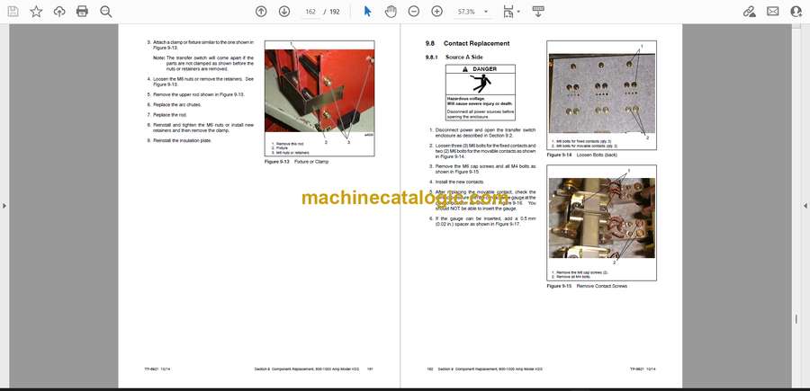
9.8 Contact Replacement . . . . . . . . . . . . . . . . . . . . . . . . . . . . . . . . . . . . . . . . . . . . . . . . . . 162
9.8.1 Source A Side . . . . . . . . . . . . . . . . . . . . . . . . . . . . . . . . . . . . . . . . . . . . . . . . . 162
9.8.2 Source B Side . . . . . . . . . . . . . . . . . . . . . . . . . . . . . . . . . . . . . . . . . . . . . . . . . 164
9.8.3 Replacement of the Mechanical Unit . . . . . . . . . . . . . . . . . . . . . . . . . . . . . 165
9.9 Reconnect Power and Test . . . . . . . . . . . . . . . . . . . . . . . . . . . . . . . . . . . . . . . . . . . . . . 166
Section 10 Component Replacement, 800–3000 Amp KGS/KGP . . . . . . . . . . . . . . . . . . . . . . . . . . . . . . . 167
10.1 Introduction . . . . . . . . . . . . . . . . . . . . . . . . . . . . . . . . . . . . . . . . . . . . . . . . . . . . . . . . . . . 167
10.2 Disconnect Power . . . . . . . . . . . . . . . . . . . . . . . . . . . . . . . . . . . . . . . . . . . . . . . . . . . . . 167
10.3 Contact Assembly Removal and Replacement . . . . . . . . . . . . . . . . . . . . . . . . . . . . . 168
10.3.1 800–1200 Amp Models . . . . . . . . . . . . . . . . . . . . . . . . . . . . . . . . . . . . . . . . . 168
10.3.2 1600–2000 Amp Models . . . . . . . . . . . . . . . . . . . . . . . . . . . . . . . . . . . . . . . . 170
10.3.3 3000 Amp Model . . . . . . . . . . . . . . . . . . . . . . . . . . . . . . . . . . . . . . . . . . . . . . 172
10.4 Auxiliary Switch Removal and Replacement . . . . . . . . . . . . . . . . . . . . . . . . . . . . . . . 174
10.5 Reconnect Power and Test . . . . . . . . . . . . . . . . . . . . . . . . . . . . . . . . . . . . . . . . . . . . . . 175
Appendix A Abbreviations . . . . . . . . . . . . . . . . . . . . . . . . . . . . . . . . . . . . . . . . . . . . . . . . . . . . . . . . . . . . . . . . 177
Appendix B Screen Summaries . . . . . . . . . . . . . . . . . . . . . . . . . . . . . . . . . . . . . . . . . . . . . . . . . . . . . . . . . . . . 179
Appendix C Noise and Wiring Practices . . . . . . . . . . . . . . . . . . . . . . . . . . . . . . . . . . . . . . . . . . . . . . . . . . . . 184
Appendix D Common Hardware Application Guidelines . . . . . . . . . . . . . . . . . . . . . . . . . . . . . . . . . . . . . 185
Appendix E General Torque Specifications . . . . . . . . . . . . . . . . . . . . . . . . . . . . . . . . . . . . . . . . . . . . . . . . . 186
Appendix F Common Hardware Identification . . . . . . . . . . . . . . . . . . . . . . . . . . . . . . . . . . . . . . . . . . . . . . . 187
Appendix G Common Hardware List . . . . . . . . . . . . . . . . . . . . . . . . . . . . . . . . . . . . . . . . . . . . . . . . . . . . . . . 188


