Format: PDF (Printable Document)
File Language: English
File Pages: 71
File Size: 3.08 MB (Speed Download Link)
Brand: Kohler
Model: KB Automatic Transfer Switches
Book No: tp5724
Type of Document: Operation and Installation Manual
$ 40
These KB automatic transfer switches sit between your utility power and your generator, usually in commercial buildings, farms, or light industrial sites where you can’t afford long outages. This manual is what I keep handy when I’m installing a new switch, verifying wiring, or chasing down why the load didn’t transfer during a power failure. For example, if the generator starts but the building never picks up on emergency power, this is the book I’d use to trace the control signals and confirm the switch is operating the way Kohler intended.
Applications & Use Cases
FAQ
Q: Can I keep this manual on a tablet or phone in the field?
A: Yes, a digital copy works well; just make sure diagrams are readable and zoomable before you rely on it.
Q: Should I print the whole manual?
A: I’d at least print the wiring diagrams and key procedures so you’ve got them if your device dies mid-job.
Safety Note
Always de-energize and lock out both utility and generator sources before opening or working inside the transfer switch.
SUBJECT PAGE SUBJECT PAGE
Safety Precautions and Instructions . . . . . . I
Introduction . . . . . . . . . . . . . . . . . . . . . . . . . . . . i
Service Assistance . . . . . . . . . . . . . . . . . . . . . . i
Section 1. Specifications . . . . . . . . . . . . . . . . 1-1
Transfer Switch Description . . . . . . . . . . . . . . . . 1-1
Purpose of Automatic Transfer Switch . . . . . . . 1-1
Purpose of Bypass/Isolation Switch . . . . . . . . . 1-1
Components of Switch . . . . . . . . . . . . . . . . . . . . 1-1
Ratings . . . . . . . . . . . . . . . . . . . . . . . . . . . . . . . . . 1-3
Interpreting a Transfer Switch Part Number . . 1-4
Specifications . . . . . . . . . . . . . . . . . . . . . . . . . . . . 1-5
Logic Specifications . . . . . . . . . . . . . . . . . . . . . . . 1-5
ATS/BIS Specifications . . . . . . . . . . . . . . . . . . . . 1-6
Section 2. Transfer Switch Operation . . . . 2-1
Switches and Indicators . . . . . . . . . . . . . . . . . . . 2-1
Description of Bypass/Isolation
Switch Components . . . . . . . . . . . . . . . . . . . . . 2-1
Description of the Bypass/Isolation
Status Panel Lamps . . . . . . . . . . . . . . . . . . . . . 2-2
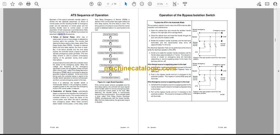
ATS Sequence of Operation . . . . . . . . . . . . . . . 2-5
Operation of the Bypass/Isolation Switch . . . . 2-6
Electric Operation Test . . . . . . . . . . . . . . . . . . . . 2-9
Bypass/Isolation Switch Operation Notes . . . . 2-10
Preventive Maintenance . . . . . . . . . . . . . . . . . . . 2-10
Manual Load Transfer . . . . . . . . . . . . . . . . . . . . . 2-10
Disconnecting the Control Panel . . . . . . . . . . . . 2-10
Disconnecting the Plug . . . . . . . . . . . . . . . . . . . . 2-10
Reconnecting the Plug . . . . . . . . . . . . . . . . . . . . 2-10
Section 3. Removal and Reconnection . . . 3-1
To Remove the ATS . . . . . . . . . . . . . . . . . . . . . . 3-1
To Reconnect the ATS . . . . . . . . . . . . . . . . . . . . 3-1
Section 4. Accessories . . . . . . . . . . . . . . . . . . 4-1
Optional Accessories . . . . . . . . . . . . . . . . . . . . . 4-1
Loose Accessories . . . . . . . . . . . . . . . . . . . . . . . 4-7
Accessory Cards . . . . . . . . . . . . . . . . . . . . . . . . . 4-7
Accessory 4. Time Delay Engine Cooldown . . 4-8
Accessory 5. Frequency, Volts, and Phase
Sequence . . . . . . . . . . . . . . . . . . . . . . . . . . . . . . 4-8
Accessory 6. Test Selector Switch . . . . . . . . . . 4-9
Accessory 7. Operation Mode Selector
Switch with Lamp . . . . . . . . . . . . . . . . . . . . . . . 4-10
Accessory 8. Bypass Time Delay Override
Switch . . . . . . . . . . . . . . . . . . . . . . . . . . . . . . . . . 4-11
Accessory 12. Panel Lamps . . . . . . . . . . . . . . . 4-12
Accessory 14. Auxiliary Contacts . . . . . . . . . . . 4-13
Accessories 23-C, D & G.
14-Day Generator Set Exercising Timer . . . . 4-13
Accessory 24. Battery Charger . . . . . . . . . . . . . 4-21
Accessory 34. Motor Load Transfer,
Inphase Monitor or Sync-Check Relay . . . . . 4-21
Accessory 35. Load-Shedding Contacts . . . . . 4-24
Section 5. Diagrams and Drawings . . . . . . . 5-1
Section 6. Installation . . . . . . . . . . . . . . . . . . . 6-1
Upon Receipt of Unit . . . . . . . . . . . . . . . . . . . . . . 6-1
Unpacking . . . . . . . . . . . . . . . . . . . . . . . . . . . . . . . 6-1
Inspection . . . . . . . . . . . . . . . . . . . . . . . . . . . . . . . 6-1
Lifting . . . . . . . . . . . . . . . . . . . . . . . . . . . . . . . . . . . 6-1
Storage . . . . . . . . . . . . . . . . . . . . . . . . . . . . . . . . . 6-1
Mechanical Installation . . . . . . . . . . . . . . . . . . . . 6-2
Remove the Transfer Switch . . . . . . . . . . . . . . . 6-2
Supporting Foundation . . . . . . . . . . . . . . . . . . . . 6-2
Mounting . . . . . . . . . . . . . . . . . . . . . . . . . . . . . . . . 6-2
Electrical Connections . . . . . . . . . . . . . . . . . . . . 6-3
Testing Power Cable . . . . . . . . . . . . . . . . . . . . . . 6-3
Connecting Power Cables . . . . . . . . . . . . . . . . . 6-3
Bus Connections . . . . . . . . . . . . . . . . . . . . . . . . . 6-3
Harnesses . . . . . . . . . . . . . . . . . . . . . . . . . . . . . . . 6-3
Engine Starting Contacts . . . . . . . . . . . . . . . . . . 6-3
Installing the transfer switch . . . . . . . . . . . . . . . . 6-4
Nonpowered Inspections . . . . . . . . . . . . . . . . . . 6-5
Inspection 1 . . . . . . . . . . . . . . . . . . . . . . . . . . . . . . 6-5
Inspection 2 . . . . . . . . . . . . . . . . . . . . . . . . . . . . . . 6-5
Inspection 3 . . . . . . . . . . . . . . . . . . . . . . . . . . . . . . 6-6
Functional Tests . . . . . . . . . . . . . . . . . . . . . . . . . . 6-6
Voltage Checks . . . . . . . . . . . . . . . . . . . . . . . . . . 6-6
Manual Operation Check . . . . . . . . . . . . . . . . . . 6-6
Electrical Operation Test . . . . . . . . . . . . . . . . . . . 6-8
Appendix A. Glossary of Abbreviations . . A-1


