Format: PDF (Printable Document)
File Language: English
File Pages: 57
File Size: 1.81 MB (Speed Download Link)
Brand: Kohler
Model: MMS, MNS, TES, TLS, ZCS, ZCB Automatic Transfer Switches
Book No: tp5670
Type of Document: Service and Parts Manual
$ 40
These Kohler automatic transfer switches sit between your utility feed and generator, usually in plant rooms, hospitals, data centers, or commercial buildings, and their whole job is to move the load cleanly when the power source changes. This manual helps you match every relay, lug kit, controller, and enclosure part on MMS, MNS, TES, TLS, ZCS, and ZCB switches to the correct Kohler part number before you order. When you’ve got a burned contactor, cracked terminal block, or a damaged wiring harness during a teardown, this is what you use to trace what you’re holding in your hand back to the right listing.
Applications & Use Cases
FAQ
Q: Can I use this manual on a tablet in the field?
A: Yes, it’s practical to keep a PDF on a tablet or laptop so you can zoom in on diagrams and part callouts at the switch.
Q: Is it worth printing sections of this manual?
A: Many techs print the pages for the exact switch model they’re working on and keep them in a job folder to mark notes and part quantities.
Safety Note
Always isolate all power sources and verify the transfer switch is de-energized before opening the enclosure or handling any components.
SUBJECT PAGE SUBJECT PAGE
Safety Precautions and Instructions . . . . . . . . I
Introduction . . . . . . . . . . . . . . . . . . . . . . . . . . . . . . i
List of Related Manuals . . . . . . . . . . . . . . . . . . . . . i
Service Assistance . . . . . . . . . . . . . . . . . . . . . . . . i
Section 1. Specifications . . . . . . . . . . . . . . . . . . 1-1
Purpose of Switch . . . . . . . . . . . . . . . . . . . . . . . . . . 1-1
Components of Switch . . . . . . . . . . . . . . . . . . . . . . 1-1
Ratings . . . . . . . . . . . . . . . . . . . . . . . . . . . . . . . . . . . 1-2
Interpreting a Transfer Switch Part Number . . . . 1-3
Specifications . . . . . . . . . . . . . . . . . . . . . . . . . . . . . . 1-5
Standard Features . . . . . . . . . . . . . . . . . . . . . . . . 1-5
Optional Features . . . . . . . . . . . . . . . . . . . . . . . . 1-5
Section 2. Operation . . . . . . . . . . . . . . . . . . . . . . 2-1
Control Switches and Indicators . . . . . . . . . . . . . . 2-1
Sequence of Operation . . . . . . . . . . . . . . . . . . . . . . 2-2
Normal Source Failure . . . . . . . . . . . . . . . . . . . . 2-2
Normal Source Restoration . . . . . . . . . . . . . . . . 2-2
Main Circuit Board Voltage Adjustments . . . . . . . 2-4
To Disconnect The P1 Plug . . . . . . . . . . . . . . . . 2-4
To Reconnect The P1 Plug . . . . . . . . . . . . . . . . . 2-4
Voltage Checks . . . . . . . . . . . . . . . . . . . . . . . . . . . . 2-5
Electrical Operation Test . . . . . . . . . . . . . . . . . . . 2-6
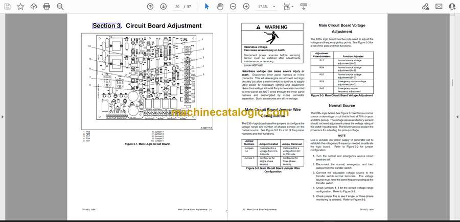
Section 3. Circuit Board Adjustment . . . . . . . 3-1
Main Circuit Board Jumper Wire Configuration . 3-2
Main Circuit Board Voltage Adjustment . . . . . . . . 3-2
Normal Source . . . . . . . . . . . . . . . . . . . . . . . . . . . . . 3-2
For Single-Phase Monitoring . . . . . . . . . . . . . . . . . 3-3
For Three-Phase Monitoring . . . . . . . . . . . . . . . . . 3-3
Emergency Source . . . . . . . . . . . . . . . . . . . . . . . . . 3-3
Section 4. Controller Troubleshooting . . . . . 4-1
General Troubleshooting Information . . . . . . . . . . 4-1
Logic Board Troubleshooting . . . . . . . . . . . . . . . . . 4-1
Interface Relay Board Troubleshooting . . . . . . . . 4-3
Section 5. Accessory Troubleshooting . . . . . 5-1
Optional Features Troubleshooting . . . . . . . . . . . . 5-2
Accessories 23-P: 7-Day, Solid-State Exercise
Timer . . . . . . . . . . . . . . . . . . . . . . . . . . . . . . . . 5-2
Specifications . . . . . . . . . . . . . . . . . . . . . . . . . . . . 5-2
Adjustment . . . . . . . . . . . . . . . . . . . . . . . . . . . . . . 5-2
Troubleshooting . . . . . . . . . . . . . . . . . . . . . . . . . . 5-5
Accessory 24-XX-A,B Battery Charger . . . . . . . 5-6
Specifications . . . . . . . . . . . . . . . . . . . . . . . . . . . . 5-6
Features . . . . . . . . . . . . . . . . . . . . . . . . . . . . . . . . 5-6
To Disconnect Charger (When Replacing or
Servicing Battery) . . . . . . . . . . . . . . . . . . . . . . . 5-8
Battery Charger Operation . . . . . . . . . . . . . . . . . 5-8
Charger Voltage Adjustment . . . . . . . . . . . . . . . 5-9
Charger and Battery Maintenance . . . . . . . . . . 5-9
Troubleshooting . . . . . . . . . . . . . . . . . . . . . . . . . . 5-9
Battery Charger Wiring Diagrams . . . . . . . . . . . 5-10
Accessory DA-26 . . . . . . . . . . . . . . . . . . . . . . . . . . 5-16
Troubleshooting . . . . . . . . . . . . . . . . . . . . . . . . . . 5-16
Section 6. Wiring Diagrams . . . . . . . . . . . . . . . . 6-1
Section 7. Service Parts . . . . . . . . . . . . . . . . . . . 7-1
Inner Panel . . . . . . . . . . . . . . . . . . . . . . . . . . . . . . . . 7-1
Accessories . . . . . . . . . . . . . . . . . . . . . . . . . . . . . . . 7-3
Plant Exercisers . . . . . . . . . . . . . . . . . . . . . . . . . . 7-3
Battery Chargers . . . . . . . . . . . . . . . . . . . . . . . . . 7-3
Three-Phase Sensing . . . . . . . . . . . . . . . . . . . . . 7-3
Appendix A. Glossary of Abbreviations . . . . A-1


