Format: PDF (Printable Document)
File Language: English
File Pages: 64
File Size: 1.51 MB (Speed Download Link)
Brand: Kohler
Model: Surveyor Program Automatic Transfer Switches
Book No: tp6214
Type of Document: Software Manual
$ 40
These Kohler MMS/MNS automatic transfer switches sit between your utility and generator, usually in plant rooms, data centers, or commercial buildings, making sure the load jumps to standby power when the grid drops. This manual is what I keep handy when I’ve got a switch open on the bench and need to match every relay, lug kit, and wiring harness to the right Kohler part number. If, for example, a transfer fails to re-engage the utility source and I find a heat-damaged operator or control board, I use this book to trace the assembly breakdown and order exactly what belongs in that frame and rating.
Applications & Use Cases
FAQ
Q: Can I use this manual on a tablet at the jobsite?
A: Yes, it’s practical to keep a digital copy; you can zoom in on diagrams and search part descriptions quickly.
Q: Is it worth printing sections of this manual?
A: Printing the pages for your exact switch model makes bench work easier, since you can mark notes and compare parts without handling a device.
Safety Note
Always isolate all power sources and verify the switch is de-energized before opening, testing, or replacing any components.
SUBJECT PAGE SUBJECT PAGE
Safety Precautions and Instructions . . . . . . I
Introduction . . . . . . . . . . . . . . . . . . . . . . . . . . . . i
List of Related Manuals . . . . . . . . . . . . . . . . . . . i
Service Assistance . . . . . . . . . . . . . . . . . . . . . . i
Notes . . . . . . . . . . . . . . . . . . . . . . . . . . . . . . . . . . ii
Section 1. Specifications . . . . . . . . . . . . . . . . 1-1
Purpose of Switch . . . . . . . . . . . . . . . . . . . . . . . . 1-1
Components of Switch . . . . . . . . . . . . . . . . . . . . 1-1
Ratings . . . . . . . . . . . . . . . . . . . . . . . . . . . . . . . . . 1-3
Interpreting a Transfer Switch Part Number . . 1-4
Specifications . . . . . . . . . . . . . . . . . . . . . . . . . . . . 1-5
Standard Features . . . . . . . . . . . . . . . . . . . . . . . . 1-5
Contactor Ratings . . . . . . . . . . . . . . . . . . . . . . . . 1-5
Section 2. Operation . . . . . . . . . . . . . . . . . . . . 2-1
Switches and Indicators . . . . . . . . . . . . . . . . . . . 2-1
Automatic Operation . . . . . . . . . . . . . . . . . . . . . . 2-1
Initial Settings . . . . . . . . . . . . . . . . . . . . . . . . . . . . 2-1
Automatic Operation Procedures . . . . . . . . . . . 2-1
Manual Operation . . . . . . . . . . . . . . . . . . . . . . . . 2-2
Units with 40–160 Ampere Ratings . . . . . . . . . . 2-2
Units with 250–1250 Ampere Ratings . . . . . . . . 2-3
Units with 1600–4000 Ampere Ratings . . . . . . 2-5
Sequence of Operation . . . . . . . . . . . . . . . . . . . . 2-7
Normal Source Failure . . . . . . . . . . . . . . . . . . . . 2-7
Normal Source Restoration . . . . . . . . . . . . . . . . 2-7
Accessories . . . . . . . . . . . . . . . . . . . . . . . . . . . . . 2-8
Time Delay Off . . . . . . . . . . . . . . . . . . . . . . . . . . . 2-8
Other Accessories . . . . . . . . . . . . . . . . . . . . . . . . 2-8
Section 3. General Maintenance . . . . . . . . . . 3-1
Section 4. Troubleshooting . . . . . . . . . . . . . . 4-1
Troubleshooting Table . . . . . . . . . . . . . . . . . . . . . 4-1
Section 5. Accessory Testing
and Adjustment . . . . . . . . . . . . . . . . . . . . . . . 5-1
Programmed Transition . . . . . . . . . . . . . . . . . . . 5-1
Other Accessories . . . . . . . . . . . . . . . . . . . . . . . . 5-1
Section 6. Disassembly/Reassembly . . . . . . 6-1
Introduction . . . . . . . . . . . . . . . . . . . . . . . . . . . . . . 6-1
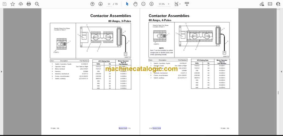
Contactor Removal
40-1250 Ampere ATS Units . . . . . . . . . . . . . . . 6-1
Contactor Installation
40-1250 Ampere ATS Units . . . . . . . . . . . . . . . 6-2
Contactor Removal
1600-4000 Ampere ATS Units . . . . . . . . . . . . 6-2
Contactor Installation
1600-4000 Ampere ATS Units . . . . . . . . . . . . 6-3
Contactor Component Removal
and Installation . . . . . . . . . . . . . . . . . . . . . . . . . . 6-4
Mechanical Interlock Removal
40-160 Ampere ATS Units . . . . . . . . . . . . . . . . 6-4
Mechanical Interlock Installation
40-160 Ampere ATS Units . . . . . . . . . . . . . . . . 6-5
Mechanical Interlock Removal
250-1250 Ampere ATS Units . . . . . . . . . . . . . . 6-5
Mechanical Interlock Installation
250-1250 Ampere ATS Units . . . . . . . . . . . . . . 6-6
Mechanical Interlock Removal
1600-4000 Ampere ATS Units . . . . . . . . . . . . 6-6
Mechanical Interlock Installation
1600-4000 Ampere ATS Units . . . . . . . . . . . . 6-7
Motor Operator Removal
40-160 Ampere ATS Units . . . . . . . . . . . . . . . . 6-8
Motor Operator Installation
40-160 Ampere ATS Units . . . . . . . . . . . . . . . . 6-9
Motor Operator Removal
250-1250 Ampere ATS Units . . . . . . . . . . . . . . 6-9
Motor Operator Installation
250-1250 Ampere ATS Units . . . . . . . . . . . . . . 6-10
Auxiliary Switch Removal
40-1250 Ampere ATS Units . . . . . . . . . . . . . . . 6-11
Auxiliary Switch Installation
40-1250 Ampere ATS Units . . . . . . . . . . . . . . . 6-11
Section 7. Service Parts . . . . . . . . . . . . . . . . . 7-1
Introduction . . . . . . . . . . . . . . . . . . . . . . . . . . . . . . 7-1
Using Parts Lists . . . . . . . . . . . . . . . . . . . . . . . . . 7-1
Finding Parts Information . . . . . . . . . . . . . . . . . . 7-1
Leads . . . . . . . . . . . . . . . . . . . . . . . . . . . . . . . . . . . 7-1
Appendix A. Glossary of Abbreviations . . A-1


