Format: PDF (Printable Document)
File Language: English
File Pages: 75
File Size: 1.48 MB (Speed Download Link)
Brand: Kohler
Model: G120 Automatic Transfer Switches
Book No: tp5992
Type of Document: Service and Parts Manual
$ 40
These Kohler G120 automatic transfer switches live in electrical rooms, plant rooms, and outdoor enclosures, quietly handling the handoff between utility power and your generator. This service and parts manual helps you match every bracket, relay, lug kit, and harness in that cabinet to the right Kohler part number before you order. When you’re chasing a nuisance transfer issue and have the switch gutted on the wall, this book lets you identify exactly which contactor assembly or control board you’re looking at so you don’t guess and buy the wrong piece.
Applications & Use Cases
FAQ
Q: Can I use this manual on a tablet while I’m at the switchgear lineup?
A: Yes, it works well digitally; you can zoom in on the diagrams and search part descriptions instead of flipping paper pages.
Q: Is it worth printing sections of this manual?
A: Many techs print the relevant parts pages for a specific switch and keep them in a job folder to avoid getting a full manual dirty.
Safety Note
Always isolate and verify all power sources are de-energized before opening or servicing the transfer switch enclosure.
Safety Precautions and Instructions
Introduction
List of Related Materials
Service Assistance
Service Information
Product Information
Section Specifications
Purpose
Components
Nameplate
Model Number
Specifications
Ratings
Application Data
Section Operation
Startup
Automatic Operation
Failure of Normal Power
Restoration of Normal Power
Exerciser Function
Exerciser Switch
Exerciser Power Requirements
Manual Operation
External Test Switch
Section Scheduled Maintenance
Inspection and Service
General Inspection
Internal Inspections Procedures and Tests
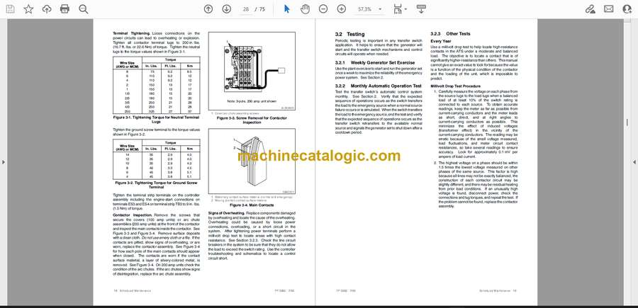
Testing
Weekly Generator Set Exercise
Monthly Automatic Operation Test
Other Tests
Service Schedule
Section Troubleshooting
General Notes on Connections
Power to the System
AC System Voltages
DC Controller Voltages
Engine Start Circuit
Exerciser Circuits
Contactor Operation
Mechanical Check
Initial Solenoid and Rectifier Troubleshooting
Solenoid Test
Rectifier Test
After Solenoid Replacement
Coil Clearing Contacts
NR/ER Relays and Controller Circuitry
Controller Operation
Emergency Source Sensing
Normal Source Sensing
Section Diagrams
Section Service Part Replacement
Before and After Servicing Components
Contactor Assembly
Contactor Assembly Removal
Contactor Assembly Installation
Solenoid Assembly
Solenoid Assembly Removal
Solenoid Assembly Installation
Controller PCB Assembly
Controller PCB Removal
Controller PCB Installation
Other Service Parts
Other Service Part Removal
Other Service Part Installation
Section Service Parts
General Information
Finding Parts Information
Leads
Common Hardware
Contactor
Controls
Decals
Enclosure
Neutral Lug
Appendix Abbreviations
Appendix Common Hardware Application Guidelines
Appendix General Torque Specifications
Appendix Common Hardware Identification
Appendix Common Hardware List


