Format: PDF (Printable Document)
File Language: English
File Pages: 58
File Size: 1.38 MB (Speed Download Link)
Brand: Kohler
Model: S340 Logic Board Automatic Transfer Switches
Book No: tp5612
Type of Document: Service Manual
$ 40
On these Kohler automatic transfer switches, the S340 logic board is what decides when to move a load between utility and generator, usually in commercial buildings, hospitals, or plants where power can’t go down. This service manual helps you trace signals through the logic board, verify inputs and outputs, and confirm a control fault before you order an expensive board. For example, when the set won’t transfer to generator even though the engine is running, this is the book you use to walk through each sensing circuit and timing function step by step.
Applications & Use Cases
FAQ
Q: Can I keep this manual on a tablet at the jobsite?
A: Yes, it’s practical to use digitally; you can zoom in on diagrams while probing terminals in the cabinet.
Q: Is it worth printing parts of this manual?
A: Many techs print the key diagnostic and wiring pages so they can mark readings and tape them inside the switch door.
Safety Note
Always de-energize and lock out all power sources before touching the logic board or any transfer switch wiring.
SUBJECT PAGE SUBJECT PAGE
Safety Precautions and Instructions . . . . . . . i
Introduction . . . . . . . . . . . . . . . . . . . . . . . . . . . . . iii
Service Assistance . . . . . . . . . . . . . . . . . . . . . . iii
Nameplate . . . . . . . . . . . . . . . . . . . . . . . . . . . . . iii
Glossary of Abbreviations . . . . . . . . . . . . . . . . v
Section 1. Specifications . . . . . . . . . . . . . . . . . . 1-1
Standard Features . . . . . . . . . . . . . . . . . . . . . . . 1-1
General Maintenance . . . . . . . . . . . . . . . . . . . . 1-2
Section 2. Adjustment . . . . . . . . . . . . . . . . . . . . 2-1
Disconnecting the Inner
Control Panel Assembly . . . . . . . . . . . . . . . . . . 2-1
To Disconnect the Control Panel . . . . . . . . . 2-1
To Reconnect the Plug . . . . . . . . . . . . . . . . . 2-1
Main Circuit Board Voltage
and Time Delay Adjustments . . . . . . . . . . . . 2-1
Accessory Card Adjustments . . . . . . . . . . . 2-2
Undervoltage Card . . . . . . . . . . . . . . . . . . . . 2-2
Overvoltage Card . . . . . . . . . . . . . . . . . . . . . 2-2
Frequency Cards . . . . . . . . . . . . . . . . . . . . . . 2-3
60 Hz Underfrequency
Card Adjustment . . . . . . . . . . . . . . . . . . . . . . 2-3
60 Hz Overfrequency
Card Adjustment . . . . . . . . . . . . . . . . . . . . . . 2-3
50 Hz Underfrequency
Card Adjustment . . . . . . . . . . . . . . . . . . . . . . 2-3
50 Hz Overfrequency
Card Adjustment . . . . . . . . . . . . . . . . . . . . . . 2-3
Time Delay Engine Cooldown Card . . . . . . . . 2-4
Section 3. ATS Troubleshooting . . . . . . . . . . . 3-1
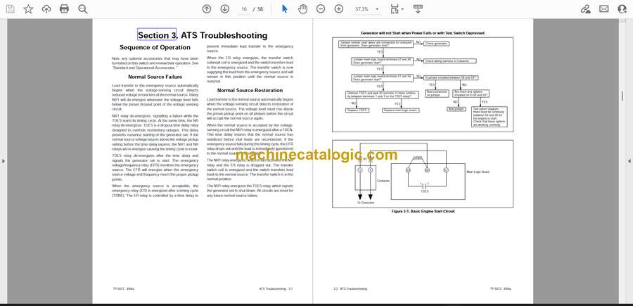
Sequence of Operation . . . . . . . . . . . . . . . . . . . 3-1
Normal Source Failure . . . . . . . . . . . . . . . . . 3-1
Normal Source Restoration . . . . . . . . . . . . . 3-1
Standard Features . . . . . . . . . . . . . . . . . . . . . . . 3-4
Standard Accessories . . . . . . . . . . . . . . . . . . . . 3-5
Optional Accessories . . . . . . . . . . . . . . . . . . . . 3-5
Loose Accessories . . . . . . . . . . . . . . . . . . . . . . 3-11
Accessory Card Troubleshooting . . . . . . . . . . 3-13
Section 4. Wiring Diagrams . . . . . . . . . . . . . . . 4-1


