Format: PDF (Printable Document)
File Language: English
File Pages: 208
File Size: 8.73 MB (Speed Download Link)
Brand: Cat
Model: 24H Motor Grader Power Train and Machine Systems
Book No: SESV1693
Type of Document: Service Training Guide
$ 40
Out on haul roads and mine sites, a 24H grader lives in dust, vibration, long pushes, and operators who don’t baby the machine. This training manual walks you through how the power train and machine systems actually work, so you can trace faults, not just throw parts. Say the machine won’t pull in a higher gear under load—you’ll learn how to isolate whether it’s a control issue, a slipping clutch, or a hydraulic problem before you start guessing.
Applications & Use Cases
FAQ
Q: Is this a downloadable manual I can search on my laptop?
A: Yes, it’s typically a digital file you can search by keyword, which makes tracing a system a lot quicker.
Q: Can I print pages and take them to the machine without ruining the book?
A: You probably should; most folks print the schematics or procedures they need and stick them in a plastic sleeve for field use.
Safety Note
Always verify the machine is properly supported and de-energized before you route hands or tools anywhere near the power train or hydraulic pinch points.
INTRODUCTION ……………………………………………………………………………………………………7
HYDRAULIC AND STEERING SYSTEM ………………………………………………………………20
System Operation………………………………………………………………………………………………22
Hydraulic System Components……………………………………………………………………………23
Hydraulic Pumps……………………………………………………………………………………………….26
Low Pressure Standby………………………………………………………………………………………..30
True Low Pressure Standby ………………………………………………………………………………..31
Combination Valve…………………………………………………………………………………………….32
Pump Compensator Valve Operation……………………………………………………………………34
Engine Off………………………………………………………………………………………………………..34
Low Pressure Standby………………………………………………………………………………………..35
Upstroking………………………………………………………………………………………………………..37
Constant Flow …………………………………………………………………………………………………..39
Destroking………………………………………………………………………………………………………..40
High Pressure Stall…………………………………………………………………………………………….42
Combination Valve…………………………………………………………………………………………….44
Low Pressure Standby (Hold)……………………………………………………………………………..44
Signal Network …………………………………………………………………………………………………48
Implement System Schematic……………………………………………………………………………..49
Implement Control Valve Oil Flow………………………………………………………………………52
Implement Control Valve (Hold) …………………………………………………………………………52
Blade Lift Control Valve (Hold) ………………………………………………………………………….54
Blade Lift Control Valve Shifted (Raise Blade) …………………………………………………….55
Blade Cushion Arrangement……………………………………………………………………………….56
Blade Cushion Deactivated…………………………………………………………………………………57
Blade Cushion Activated ……………………………………………………………………………………57
Ripper Crossover Relief Valve…………………………………………………………………………….59
Steering System Components ……………………………………………………………………………..60
Steering Accumulator ………………………………………………………………………………………..63
Hand Metering Unit (HMU) ……………………………………………………………………………….65
Oil Flow …………………………………………………………………………………………………………..66
Steering Crossover Relief Valve ………………………………………………………………………….67
Steering Hydraulic System Oil Flow ……………………………………………………………………69
Steering System (Hold)………………………………………………………………………………………69
Hand Metering Unit (HMU) (Hold) …………………………………………………………………….70
Steering System (Right Turn) ……………………………………………………………………………..71
Secondary Steering System…………………………………………………………………………………72
Unloading Valve………………………………………………………………………………………………..74
TABLE OF CONTENTS (Continued)
BRAKE SYSTEM ………………………………………………………………………………………………….76
Brake System Schematic…………………………………………………………………………………….76
Brake Pump………………………………………………………………………………………………………79
Accumulator Charging Valve………………………………………………………………………………79
Accumulators ……………………………………………………………………………………………………83
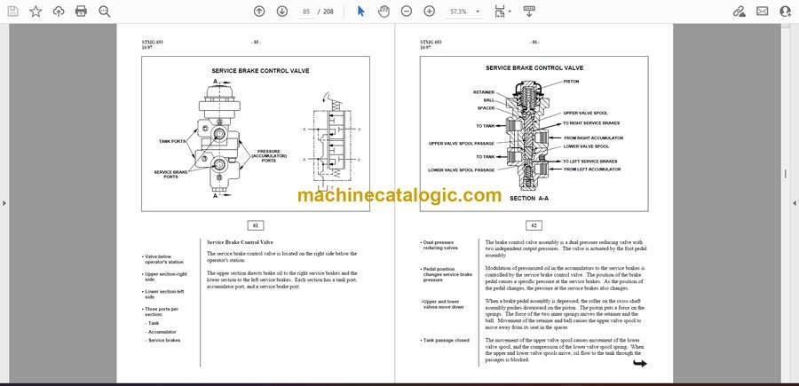
Service Brake Control Valve……………………………………………………………………………….85
Tandem Housing ……………………………………………………………………………………………….88
Service Brake Low Pressure Switch …………………………………………………………………….94
Alert Indicator and Master Action Light Locations………………………………………………..95
Slack Adjusters …………………………………………………………………………………………………96
Brake System Filters ………………………………………………………………………………………….99
Towing …………………………………………………………………………………………………………..101
Manual Release of Parking Brake for Towing……………………………………………………..101
POWER TRAIN SYSTEM…………………………………………………………………………………….102
Component Location………………………………………………………………………………………..102
Torque Converter …………………………………………………………………………………………….103
Torque Converter Drive ……………………………………………………………………………………104
One-way Clutch ………………………………………………………………………………………………106
Lockup Clutch…………………………………………………………………………………………………106
Operation………………………………………………………………………………………………………..107
Direct Drive ……………………………………………………………………………………………………108
Torque Converter Hydraulic System ………………………………………………………………….109
Converter Inlet Ratio Valve ………………………………………………………………………………109
Converter Outlet Relief Valve……………………………………………………………………………110
Lockup Clutch and Solenoid Valve…………………………………………………………………….112
Transmission Hydraulic System ………………………………………………………………………..114
Planetary Lubrication……………………………………………………………………………………….117
Input Transfer Gear Lubrication ………………………………………………………………………..118
Output Transfer Gear Lubrication………………………………………………………………………118
Oil Pump ………………………………………………………………………………………………………..119
Oil Filter…………………………………………………………………………………………………………121
Planetary Transmission …………………………………………………………………………………….123
FIRST Speed FORWARD…………………………………………………………………………………125
Transmission Hydraulic Controls ………………………………………………………………………126
Introduction…………………………………………………………………………………………………….126
Operation………………………………………………………………………………………………………..129
Selector and Pressure Control Valve Group and Selector Valve Group …………………..129
Transmission in NEUTRAL, Engine Running …………………………………………………….129
Engine Running, NEUTRAL to FIRST Speed FORWARD…………………………………..132
Lockup Clutch and Solenoid Valve…………………………………………………………………….135
Input Transfer Gears ………………………………………………………………………………………..136
Output Transfer Gears………………………………………………………………………………………138
Differential and Final Drives …………………………………………………………………………….140
Differential ……………………………………………………………………………………………………..140
Differential Lock Pump ……………………………………………………………………………………142
Differential Lock Valve…………………………………………………………………………………….143
Final and Tandem Drives ………………………………………………………………………………….145
TRANSMISSION ELECTRONIC CONTROL SYSTEM …………………………………………147
Component Description ……………………………………………………………………………………148
Transmission Electronic Control Module (ECM)…………………………………………………148
Inputs……………………………………………………………………………………………………………..149
Outputs…………………………………………………………………………………………………………..149
Input/Output……………………………………………………………………………………………………150
Transmission Shift Lever ………………………………………………………………………………….151
Parking Brake Pressure Switch………………………………………………………………………….154
Key Start Switch ……………………………………………………………………………………………..156
Differential Lock Switch…………………………………………………………………………………..158
Sensors …………………………………………………………………………………………………………..160
Brake Pedal Position Sensor ……………………………………………………………………………..161
Transmission Neutralizer Position Sensor …………………………………………………………..162
Accelerator Pedal Sensor ………………………………………………………………………………….162
Articulation Position Sensor ……………………………………………………………………………..163
Ripper Position Sensor……………………………………………………………………………………..164
Engine Speed Sensor………………………………………………………………………………………..165
Transmission Speed Sensor ………………………………………………………………………………167
Converter Output Speed Sensor…………………………………………………………………………169
Transmission Clutch Solenoid Valve ………………………………………………………………….171
Differential Lock Solenoid Valve ………………………………………………………………………173
Lockup Clutch Solenoid Valve ………………………………………………………………………….175
Start Relay………………………………………………………………………………………………………177
Brake Lamp Relay …………………………………………………………………………………………..178
Back-up Alarm………………………………………………………………………………………………..179
CAT Data Link………………………………………………………………………………………………..180
Caterpillar Electronic Technician (ET)……………………………………………………………….182
Normal Operation ……………………………………………………………………………………………183
Directional Shift Management Function……………………………………………………………..185
Engine Overspeed Protection…………………………………………………………………………….185
Operator Requested Downshifts ………………………………………………………………………..185
Caterpillar Pre-lubrication ………………………………………………………………………………..186
Parking Brake Operation…………………………………………………………………………………..186
Back-up Alarm Operation…………………………………………………………………………………187
STMG 693 – 5 –
10/97
TABLE OF CONTENTS (Continued)
Transmission Neutralizer ………………………………………………………………………………….187
Differential Lock Function ……………………………………………………………………………….187
Diagnostic Operation ……………………………………………………………………………………….187
Caterpillar Monitoring System ………………………………………………………………………….189
Gear Indicator …………………………………………………………………………………………………190
CONCLUSION…………………………………………………………………………………………………….191
SLIDE LIST…………………………………………………………………………………………………………192
SERVICEMAN’S HANDOUTS……………………………………………………………………………..194


