Case TL100 Mini Excavator Operators Manual (92756979, B280101089) (October 2025)
On a TL100 you’re usually working tight jobsites, trenching around services, loading spoil, maybe tracking through wet clay or loose gravel. This operators manual is about how to run the machine the way it was meant to be run—how the controls respond, what to check each day, and how to keep from abusing it without realizing. Say you’re swinging over a trench on a side slope with a full bucket; the book walks you through how the boom and travel circuits behave so you don’t fight the hydraulics or tip the machine.
Applications & Use Cases
- Trace and verify control functions before a shift so you catch sticky pedals, slow joysticks, or sloppy swing before they cost you time.
- Check and bleed the hydraulic system properly when you swap attachments, so you don’t crack a fitting or pop an O‑ring by yanking a pressurized quick coupler.
- Inspect, route, and protect hoses and lines after working in brush or rubble, spotting rub points that usually turn into leaks.
- Isolate odd noises or vibrations under load—like when tracking in mud or climbing a ramp—using the normal‑operation behavior the manual describes.
- Align your daily service routine with what Case actually expects: fluid checks, filter areas, grease points, and warm‑up habits that typically extend component life.
FAQ
Q: Is this a PDF I can search on my phone or laptop?
A: Usually, yes; you can search terms like “travel control” or “aux hydraulics” so you’re not scrolling forever.
Q: Can I print just the sections I need for the jobsite?
A: You probably can; most folks print the safety, controls, and daily checks pages and keep them in a binder in the trailer.
Safety Note
Always drop the attachment, kill the engine, and release hydraulic pressure before you crack any hose or fitting, even if you think it’s cooled down.
Case TL100 Mini Excavator Index:
- 1 - Introduction
- 1.1 – Regarding this manual
- 1.1.1 – Manual consultation and terminology
- 1.2 – Machine identification data
- 1.3 – Manufacturer
- 1.3.1 – Contact the manufacturer
- 1.3.2 – Spare Parts
- 1.4 – Information to the owner of the machine
- 1.5 – Intended use
- 1.6 – Prohibited use
- 1.7 – Emissions overview
- 2 - Safety
- 2.1 – Safety symbol
- 2.2 – General safety
- 2.2.1 – Manual safety sign consultation
- 2.3 – Safety signs and operation related labels
- 2.4 – Machine driver
- 2.4.1 – Personal Protective Equipment (PPE)
- 2.5 – Work Area – Hazard Zone – No Entry Zone
- 2.6 – List of Residual Risks
- 2.7 – Safety procedures
- 2.8 – Safety devices
- 2.8.1 – Control cut-out button
- 2.8.2 – Parking brake button
- 3 - Technical data
- 3.1 – General data
- 3.2 – Engine
- 3.3 – Hydraulic system
- 3.4 – Performance
- 3.5 – Counterweight
- 3.6 – Undercarriage
- 3.7 – Fluid capacities
- 3.8 – Electrical system
- 3.9 – Brakes
- 3.10 – Operating load
- 3.10.1 – Bucket
- 3.10.2 – Pallet forks
- 3.11 – Overall dimensions
- 4 - Transporting the machine
- 4.1 – Transportation dimensions
- 4.2 – Loading/unloading operations
- 4.3 – Securing the machine on the mean of transport
- 4.4 – Lifting the machine
- 4.4.1 – Lifting procedure
- 4.5 – Recovering and pulling the machine
- 5 - Controls and instrumentation
- 5.1 – Description of controls
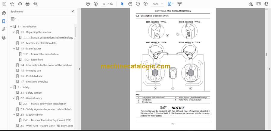
- 5.2 – Description of control levers
- 5.3 – Description of dashboard
- 5.4 – Roller operation
- 5.5 – Auxiliary power socket on console
- 5.6 – Control panel
- 5.7 – Battery isolator switch
- 5.8 – Geo-localisation system
- 6 - Using the machine
- 6.1 – Commissioning
- 6.2 – Battery isolator switch
- 6.3 – Driver seat
- 6.4 – Control cut-out button
- 6.5 – Parking brake button
- 6.6 – Visibility
- 6.7 – Starting the engine
- 6.7.1 – Inspections prior to starting
- 6.7.2 – Procedure for starting the machine
- 6.8 – Engine jump-starting procedure
- 6.8.1 – Connecting the additional cables
- 6.8.2 – Starting the engine
- 6.8.3 – Removing the additional cables
- 6.9 – Horn
- 6.10 – Work lights
- 6.11 – Operation at low temperatures or during winter
- 6.12 – Precautions during operation
- 6.13 – Stopping and parking the machine
- 6.14 – Refuelling
- 6.15 – Throttle lever
- 6.16 – Machine movement
- 6.16.1 – Left Joystick
- 6.16.2 – Forward and reverse travel
- 6.16.3 – Turning while moving forward
- 6.16.4 – Rotation while reversing
- 6.16.4.1 – Precautions during the operation of the tracks
- 6.17 – Operating the boom
- 6.17.1 – Right joystick
- 6.17.2 – Boom floating control
- 6.18 – Using the bucket
- 6.19 – Discharge residual pressure in the hydraulic system
- 6.20 – Auxiliary hydraulic systems
- 6.20.1 – Connection of equipment to the hydraulic systems
- 6.20.2 – AUX1 Auxiliary hydraulic system
- 6.20.2.1 – AUX1 hydraulic system three-way switch
- 6.20.2.2 – Single-acting mode AUX1
- 6.20.2.3 – Double-acting mode AUX1
- 6.20.2.4 – Auxiliary hydraulic system AUX1 latch with operator not in the driver’s seat
- 6.20.3 – Drain line (direct to tank – optional)
- 6.21 – Electrical auxiliary systems (optional)
- 6.21.1 – Connecting equipment to electrical systems
- 6.21.2 – Operation of electrical auxiliary systems
- 6.22 – Emergency boom lowering procedure
- 6.23 – Procedure for the temporary activation of the controls with the operator not detected in the driver’s seat
- 6.24 – Supplementary counterweight installation and removal procedure
- 6.25 – Daily storage
- 7 - Recommended optional equipment
- 7.1 – Safety precautions
- 7.2 – Specifications on authorised equipment
- 7.3 – Operating capacity
- 7.4 – Quick-coupling
- 7.5 – Precautions
- 8 - Maintenance
- 8.1 – Safety
- 8.1.1 – Putting the machine out of service for maintenance
- 8.2 – Tools and equipment for maintenance
- 8.3 – Safety devices
- 8.3.1 – Engine hood
- 8.3.2 – Electrical components guard
- 8.3.3 – Upper compartment cover (cushion)
- 8.3.4 – Lower compartment cover
- 8.3.5 – Oil tank compartment guard
- 8.4 – Locking the boom for maintenance
- 8.5 – Electrical system
- 8.6 – Tracks
- 8.7 – Refilling
- 8.7.1 – Refilling quantity table
- 8.7.2 – Products for lubrication
- 8.7.3 – Fuel
- 8.7.4 – Engine oil
- 8.7.5 – Cooling liquid
- 8.7.6 – Hydraulic system oils
- 8.7.6.1 – Requirements for using eco-friendly hydraulic oil
- 8.7.6.2 – Scheduled plan for analysis and control of ecological hydraulic oil
- 8.7.6.3 – Requirements for the sampling of eco-friendly hydraulic oil
- 8.8 – Battery
- 8.8.1 – Fitting and removing the battery
- 8.8.2 – Recharging the battery
- 8.9 – Tightening torque tables
- 8.10 – Weights of the material in a pile
- 8.11 – Regular maintenance
- 8.11.1 – Performance check
- 8.11.2 – Check of engine oil level
- 8.11.3 – Replacement of engine oil
- 8.11.4 – Replacement of engine oil filter
- 8.11.5 – Check of cooling liquid level
- 8.11.6 – Replacement of cooling liquid
- 8.11.7 – Check and replacement of cooling liquid sleeves
- 8.11.8 – Cleaning the radiator
- 8.11.9 – Check of hydraulic oil level
- 8.11.10 – Change discharge circuit hydraulic oil filter
- 8.11.11 – Hydraulic system oil sampling/replacement
- 8.11.12 – Replacement of intake circuit hydraulic oil filter
- 8.11.13 – Check of hydraulic line condition
- 8.11.14 – Checking that the screws of the undercarriage are tight
- 8.11.15 – Check of track tension
- 8.11.16 – Adjusting the track tension
- 8.11.17 – Checking tension and replacing alternator belt
- 8.11.18 – Checking tension and replacing fan belt
- 8.11.19 – Check and replacement of air filter
- 8.11.20 – Replacement of fuel filter
- 8.11.21 – Draining the fuel tank
- 8.11.22 – Draining fuel circuit water and replacing water separator filter
- 8.11.23 – Cleaning the filter on the fuel intake
- 8.11.24 – Bleeding air from the fuel circuit
- 8.11.25 – Replacement of travel engine oil
- 8.12 – Lubrication of pins
- 8.13 – Long inactivity periods
- 8.14 – Dismantling the machine
- 9 - electrical components
- 9.1 – Fuses and relays
- 9.1.1 – Control box fuses
- 9.1.2 – Control unit relays
- 9.1.3 – Engine fuses and relays
- 9.2 – Work lights replacement
- 9.3 – LED strip replacement
CNH


