Develon DX60R Mini Excavator Shop Manual (50001 and Up) (K1042957E)
Out on small sites, driveways, and tight commercial lots, the DX60R usually spends its life trenching, loading trucks, and cleaning up around utilities. This shop manual is what you’d use when you’re past simple filters and grease and you’re ready to tear deeper in—track drives, swing gear, boom and arm, even cab and hydraulics. Say you’ve got a weak boom and a mystery oil sheen under the machine; this is what you’d follow to trace the leak, pull the cylinder, inspect the internals, and then reassemble it without guessing on torque or hose routing.
Applications & Use Cases
- Plan a full teardown by laying out your workspace, tagging hoses, and routing harnesses so you don’t fight it on reassembly.
- Trace hydraulic faults step‑by‑step, isolate a bad section, then test and bleed the system after you’ve swapped components.
- Check wear on pins, bushings, and slew components while it’s apart, so you can replace what’s borderline before it goes back together.
- Follow general torque sequences and alignment tips to verify you’re not loading the frame, boom foot, or final drives crooked.
- Inspect swing, travel, and blade systems after repairs and align everything so the machine tracks straight and digs square.
FAQ
Q: Is this a searchable PDF I can keep on a laptop or tablet?
A: Yes, it’s generally a PDF you can search by keyword, which makes it quicker to jump to the system you’re working on.
Q: Can I print just the sections I need to bring to the jobsite?
A: You usually can; most folks print the relevant procedures, stick them in a clear sleeve, and don’t worry about getting them dirty.
Safety Note
Always block, support, and relieve pressure before you crawl under or crack any hydraulic line, even on a “small” excavator like this.
Develon DX60R Mini Excavator Index:
- DX60R
- Table of Contents
- Safety
- Track Excavator Safety SP001614
- Safety Precautions
- Applicable Models
- To the Operator of a Excavator
- Learn the Signal Words Used with the Safety Alert Symbol
- General Safety Essentials
- Accessory Applications
- Lifting Capacity Rating Configuration
- Location of Safety Labels
- Summary of Safety Precautions for Lifting in Digging Mode
- Unauthorized Modifications
- General Hazard Information
- Safety Rules
- Safety Features
- Inside Operator’s Cabin
- Clothing and Personal Protective Items
- Breathing Masks, Ear Protection May Be Required
- Vibration Level Information
- Recommendations for Limiting Vibrations
- Mounting and Dismounting
- Fuel, Oil and Hydraulic Fluid Fire Hazards
- Precautions When Handling Fluids at High Temperature
- Asbestos Dust Hazard Prevention
- Injury from Work Equipment
- Fire Extinguisher and First Aid Kit
- Protection from Falling or Flying Objects
- Attachment Precautions
- Accumulator
- Indoor Ventilation
- Emergency Exit
- Before Starting Engine
- Work Site Precautions
- Checks Before Starting Engine
- Engine Starting
- Before Operating Machine
- Machine Operation
- When Swinging or Changing Direction of Travel
- Travel Precautions
- Traveling on Slopes
- Prohibited Operations
- Precautions for Operation
- Avoid High�voltage Cables
- Operate Carefully on Snow, Ice and in Very Cold Temperatures
- Operations on Slopes
- Parking Machine
- Precautions for Traveling in Reverse
- Never Let Anyone Ride on Attachment
- Maintenance
- Warning Tag
- Clean Before Inspection or Maintenance
- Proper Tools
- Use of Lighting
- Fire Prevention and Explosion Prevention
- Burn Prevention
- Welding Repairs
- Preparation for Electrical Welding on Body Structure
- Warning for Counterweight and Front Attachment Removal
- Precautions for Removal, Installation, and Storage of Attachments
- Precautions When Working on Machine
- Lock Inspection Covers
- Prevention of Crushing and Cutting
- Track Tension Adjustment Requires Caution
- Supports and Blocks for Work Equipment
- Action When Abnormality Is Found During Inspection
- Precautions with High�pressure Lines, Tubes and Hoses
- Waste Materials
- Cabin Tilting
- Battery
- Battery Hazard Prevention
- Boost Starting or Charging Engine Batteries
- Towing
- Shipping and Transportation
- Obey State and Local Over�the�Road Regulations
- Lifting With Sling
- Specifications
- Specification for DX60R SP001615
- Safety Precautions
- Applicable Models
- General Description
- Component Locations
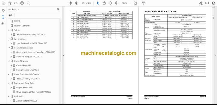
- Overall Dimensions
- Working Range
- Standard Specifications
- Engine Performance Curves
- Approximate Weight of Workload Materials
- Performance Tests
- Excavator Performance Standards
- Test Conditions
- Travel Speed and Travel Motor Balance (Steering Deviation) Tests
- Speed Test
- Travel Deviation
- Swing Speed and Deceleration Force Test
- Swing Speed Test
- Swing Deceleration Force Test
- Cylinder Performance Tests
- Hydraulic Cylinder
- Boom Cylinders Test
- Arm Cylinder Test
- Bucket Cylinder Test
- Hydraulic Cylinder Natural Drop Test
- Travel Motor Jack�up Test
- General Maintenance
- General Maintenance Procedures SP000016
- Safety Precautions
- Applicable Models
- Welding Precautions and Guidelines
- Hydraulic System � General Precautions
- Maintenance Service and Repair Procedure
- Hydraulic System Cleanliness and Oil Leaks
- Maintenance Precautions for Hydraulic System Service
- Oil Leakage Precautions
- Cleaning and Inspection
- General Guidelines
- Bearing Inspection
- Normal Bearing
- Bent Cage
- Galling
- Abrasive Step Wear
- Etching
- Misalignment
- Indentations
- Fatigue Spalling
- Brinelling
- Cage Wear
- Abrasive Roller Wear
- Cracked Inner Race
- Smears
- Frettage
- Heat Discoloration
- Stain Discoloration
- Standard Torques SP000813
- Safety Precautions
- Applicable Models
- Torque Values for Standard Metric Fasteners
- Torque Values for Standard U.S. Fasteners
- Type 8 Phosphate Coated Hardware
- Torque Values for Hose Clamps
- Torque Values for Split Flanges
- Torque Wrench Extension Tools
- Torque Multiplication
- Other Uses for Torque Wrench Extension Tools
- Tightening Torque Specifications (Metric)
- I. “Loctite” Fastener Adhesives
- II. “Loctite” Pipe Thread Sealant
- III. “Loctite” gasket/flange sealer
- IV. “Loctite” retaining compounds
- V. “Loctite” Adhesives
- Upper Structure
- Cabin SP001623
- Safety Precautions
- Applicable Models
- Removal
- Installation
- Swing Bearing SP001624
- Safety Precautions
- Applicable Models
- Swing Bearing Maintenance
- Operating Recommendation
- Measuring Swing Bearing Axial Play
- Measuring Bearing Lateral Play
- Swing Bearing Basic Operation
- Rebuilding Swing Bearing
- Lower Structure and Chassis
- Track Assembly SP001625
- Track Assembly
- Safety Precautions
- Applicable Models
- Tracks
- Specification and Construction
- Track Tension
- Cleaning and Inspection (Wear Limits and Tolerances)
- Rubber Track Features
- Steel Tracks
- Track Frame Spring
- Idler
- Steel Tracks
- Spring Specifications
- Lower Roller
- Upper Roller
- Sprocket
- Track Removal and Installation
- Track Removal
- Track Installation
- Replacement of Rubber Tracks with Steel Tracks
- Replacement of Steel Tracks with Rubber Tracks
- Idler
- Track Tension Adjusting Cylinder
- Parts List
- Disassembly
- Reassembly
- Lower Roller
- Steel Track
- Rubber Track
- Disassembly
- Reassembly
- Upper Roller
- Parts List
- Disassembly
- Reassembly
- Sprocket
- Engine and Drive Train
- Engine SP001693
- Safety Precautions
- Applicable Models
- Safety
- General Service Information
- Component Identification
- Location of Labels
- Function of Major Engine Components
- Main Electronic Control Components and Features
- Function of Cooling System Components
- Diesel Fuel
- Diesel Fuel Specifications
- Filling The Fuel Tank
- Priming the Fuel System
- Engine Oil
- Engine Oil Specifications
- Engine Oil Viscosity
- Checking Engine Oil
- Adding Engine Oil
- Engine Coolant
- Engine Coolant Specifications
- Filling Radiator with Engine Coolant
- Principal Engine Specifications
- Engine Service Standards
- Tightening Torques for Standard Bolts and Nuts
- Periodic Maintenance
- Before You Begin Servicing
- Introduction
- The Importance of Periodic Maintenance
- Performing Periodic Maintenance
- DOOSAN Replacement Parts
- Required EPA / ARB Maintenance – USA Only
- EPA / ARB Installation Requirements -USA Only
- Periodic Maintenance Schedule
- Periodic Maintenance Procedures
- After Initial 50 Hours of Operation
- Every 50 Hours of Operation
- Every 250 Hours of Operation
- Every 500 Hours of Operation
- Every 1000 Hours of Operation
- Every 1500 Hours of Operation
- Every 2000 Hours of operation
- Engine
- Before You Begin Servicing
- Introduction
- Cylinder Head Specifications
- Adjustment Specifications
- Cylinder Head
- Intake / Exhaust Valve and Guide
- Push Rod
- Valve Spring
- Rocker Arm and Shaft
- Camshaft and Timing Gear Train Specifications
- Camshaft
- Idler Gear Shaft and Bushing
- Timing Gear Backlash
- Crankshaft and Piston Specifications
- Crankshaft
- Thrust Bearing
- Piston
- Piston Ring
- Connecting Rod
- Tappet
- Cylinder Block Specifications
- Special Torque Chart
- Torque for Bolts and Nuts
- Special Service Tools
- Measuring Instruments
- 4-valve Cylinder Head
- 4-Valve Cylinder Head Components
- Disassembly of 4-Valve Cylinder Head
- Cleaning of Cylinder Head Components
- Inspection of Cylinder Head Components
- Inspection of Push Rods
- Inspection of Rocker Arm Assembly
- Inspection of Valve Guides
- Inspection of Cylinder Head
- Inspection of Intake and Exhaust Valves
- Reassembly of Cylinder Head
- Measuring and Adjusting Valve Clearance
- Crankshaft and Camshaft Components
- Disassembly of Engine
- Disassembly of Camshaft and Timing Components
- Disassembly of Crankshaft and Piston Components
- Inspection of Crankshaft and Camshaft Components
- Honing and Boring
- Reassembly of Crankshaft and Piston Components
- Reassembly of Camshaft and Timing Components
- Final Reassembly of Engine
- EGR System
- EGR System
- Inspecting/Cleaning EGR Related Components
- Fuel System
- Before You Begin Servicing
- Introduction
- Fuel Injection Pump
- Stop Solenoid
- Cold Start Device
- Trochoid Fuel Pump
- Electronically Controlled Governor
- Fuel System Specifications
- Special Torque Chart
- Test and Adjustment Specifications
- Special Service Tools
- Measuring Instruments
- Fuel System Diagram
- Fuel System Components
- Fuel Injection Pump
- Removal of Fuel Injection Pump
- Installation of Fuel Injection Pump
- Checking and Adjusting Fuel Injection Timing
- Determining the Fuel Injection Timing Specification
- Checking Fuel Injection Timing
- Adjusting Fuel Injection Timing
- Fuel Injectors
- Removal of Fuel Injectors
- Testing of Fuel Injectors
- Disassembly and Inspection of Fuel Injectors
- Adjusting Fuel Injector Pressure
- Reassembly of Fuel Injectors
- Installation of the Fuel Injectors
- Cooling System
- Before You Begin Servicing
- Introduction
- Cooling System Diagram
- Engine Coolant Pump Components
- Engine Coolant System Check
- Engine Coolant Pump
- Disassembly of Engine Coolant Pump
- Cleaning and Inspection
- Reassembly of Engine Coolant Pump
- Installation of Engine Coolant Pump
- Lubrication System
- Before You Begin Servicing
- Introduction
- Oil Pump Service Information
- Lubrication System Diagram
- Checking Engine Oil Pressure
- Trochoid Oil Pump
- 4TNV98 Oil Pump Components
- Disassembly of Oil Pump
- Cleaning and Inspection
- Reassembly of Oil Pump
- Starter Motor
- Before You Begin Servicing
- Introduction
- Starter Motor Specifications
- Starter Motor Troubleshooting
- Starter Motor Components
- Starter Motor
- Removal of Starter Motor
- Disassembly of Starter Motor
- Cleaning and Inspection
- Reassembly of Starter Motor
- Check Pinion Projection Length
- No-Load Test
- Installation of Starter Motor
- Alternator
- Before You Begin Servicing
- Introduction
- Alternator Specifications
- Dynamo Specifications
- Alternator Troubleshooting
- Alternator Components
- Alternator Wiring Diagram
- Alternator Standard Output
- Alternator
- Removal of Alternator
- Disassembly of Alternator
- Reassembly of Alternator
- Installation of Alternator
- Dynamo Component Location
- Dynamo Wiring Diagram
- Operation of Dynamo
- Dynamo Standard Output
- Testing of Dynamo
- Testing Stator Coil Continuity
- Testing Stator Coil Short-to-Ground
- Testing Dynamo Regulated Output
- Dynamo
- Removal of Dynamo
- Disassembly of Dynamo
- Reassembly of Dynamo
- Installation of Dynamo
- Electric Wiring
- Electric Wiring Precautions
- Electrical Wire Resistance
- Battery Cable Resistance
- Electrical Wire Sizes – Voltage Drop
- Conversion of Awg to European Standards
- Troubleshooting
- Special Service Tools
- Troubleshooting by Measuring Compression Pressure
- Compression Pressure Measurement Method
- Standard Compression Pressure (Reference Value)
- Engine Speed and Compression Pressure (Use for Reference)
- Measured Value and Troubleshooting
- Quick Reference Table for Troubleshooting
- Failure Diagnosis Table
- Electrical wiring
- Drive Coupling (Main Pump) SP001627
- Safety Precautions
- Applicable Models
- Drive Coupling
- Installation of Drive Coupling
- Hydraulics
- Accumulator SP000028
- Safety Precautions
- Applicable Models
- General Description
- Center Joint (Swivel) SP001628
- Safety Precautions
- Applicable Models
- General Description
- Disassembly
- Reassembly
- Center Joint Assembly
- Cylinders SP001629
- Safety Precautions
- Applicable Models
- General Description
- Theory of Operation
- Parts List
- Special Tools and Materials
- Piston Nut
- Piston Jig
- Steel Bushing Jig
- Dust Wiper Jig
- Slipper Seal Jig
- Slipper Seal Straightening Jig
- Disassembly
- Assembly
- Swing Motor SP001630
- Safety Precautions
- Applicable Models
- Indication of Type
- Specifications
- Construction and Principles of Working
- Construction
- Principles of Working
- Precaution in Use
- Inspection
- Rotation Direction
- External Load of Shaft
- Hydraulic Fluids and Range of Temperature
- Filter
- Installation and Piping
- Oil Filling
- Precaution in Starting Operations
- Troubleshooting
- General Cautions
- Investigation Manner of the Motor Body
- Condition and Countermeasures of Troubles
- Disassembling and Assembling
- Tightening Torque of Bolts
- Necessary Tools
- Disassembly of Motor
- Assembly of Motor
- Disassembly of Reduction Gear
- Assembly of Reduction Gear
- Maintenance Standards
- Part Replacement Standards for Hydraulic Motor
- Part Replacement Standards for Reduction Gear
- Standard for Correcting Sliding Surfaces
- Travel Motor SP001686
- Safety Precautions
- Applicable Models
- General
- Configuration
- Features
- Structural Diagram of the Travelling System
- Structural Diagram of the Axial Piston Motor
- Operating Principle
- When Travelling
- When Counterbalance Operates
- When Brake Functions
- Operating Principle of Parking Brake
- 2 Speed Limiting Function
- Parts List
- Hydraulic Motor
- Reduction Gear
- Special Tools and Materials
- Standard Tools
- Equipment and Materials
- Measuring Devices
- Manufacturing Tools
- Travel Motor Workbench
- Fixture
- Holder (I)
- Holder (II)
- Holder (IV)
- Steel Rod
- Bearing Preload Adjuster
- Tightening Torque
- Weight Table
- Travel Motor Troubleshooting
- Travel Motor
- Counterbalance Valve
- Relief Valve
- 2�Speed Change Over
- Parking Brake
- Disassembly
- Preparations
- Workbench Preparations
- Preparation of Tools and Materials
- General Suggestions When Working
- Disassembly Procedure
- Washing GM motor.
- GM Motor Installation
- Lubricating Oil Extraction
- Cover Removal
- Input Gear Removal
- Spur Gear Removal
- Rear Flange Removal
- Removing Parts from the Rear Flange
- Disassembly of Plugs Inside Rear Flange
- Disassembling Valve (For 2�Speed Control)
- Remove Hexagon Socket Plug
- Disassembling Valve for Parking Brake
- Disassembling Parking Brake
- Disassembling Hydraulic Motor
- Removal of Spring Inside Cylinder Block
- Removal of Swash Plate
- Removing Ball Bearing From Shaft
- Removing Hold Flange
- Fixture Removal
- Removing Spindle
- Removal of Ball Bearing, RV Gear Assembly, and Pin
- Ball Bearing Removal
- Disassembling Spindle Fittings
- Disassembling Hold Flange
- Washing
- Finish Washing
- Service Preparations
- Seals
- Service Standards for Parts Subject to Wear
- Assembly
- Preparation
- General Suggestions When Working
- Assembly Procedure
- Hub Section Assembly
- Spindle Assembly
- Mount RV Gear Assembly
- Hold Flange Mounting
- Tightening Reamer Bolts and Hex. Socket Bolts
- Install Retaining Rings
- Spur Gear Assembly
- Mounting Oil Seal
- Shaft Assembly
- Assembly of Cylinder Block Interior
- Assembly of Hydraulic Motor Parts
- Assembly of Parking Brake Section
- Assembly of Brake Valve Parts in Rear Flange
- Assembly of Rear Flange Mounted Parts
- Connection of Rear Flange with Spindle
- Input Gear Assembly
- Cover Assembly
- Remove Assembled GM Motor from Workbench
- Preload Adjustment of Ball Bearing
- Adjusting Axial Clearance on Tapered Roller Bearing
- Performance Confirmation Test
- Required Measuring Devices
- Test Procedure
- Clearance Adjustment Part Dimensions
- Main Control Valve SP001639
- Safety Precautions
- Applicable Models
- Composition, Function and Operation
- Function of Control Valve
- Operation of Main Section
- Disassembly
- Disassembly of Accessory
- Disassembly of Arm2, Bucket, Right Run, Left Run, Arm1, Dozer, Swing, Boom Swing Section
- Disassembly of Boom1 Section (Figure 30)
- Disassembly of Inlet Section (Figure 32)
- Disassembly of Boom2/Aux Section (Figure 35)
- Disassembly of Straight Travel Section (Figure 39)
- Take Off of Load Check Poppet Type
- Disassembly of Valve Housing
- Cleaning
- Inspection
- Assembly
- Assembly of Valve Housing
- Assembly of Arm2, Bucket, Right Run, Left Run, Arm1, Dozer, Swing, Boom2/Aux, Boom Swing
- Assembly of Boom1 Section (Figure 30)
- Assembly of Inlet Section (Figure 32)
- Assembly of Boom2/Aux Section (Figure 35)
- Assembly of Straight Travel (Figure 39)
- Inserting of Load Check
- Accessory Adherence
- Relief Valve
- Main Relief Valve (P1, P2, P3)
- Overload Relief Valve
- Pressure Adjustment of Relief Valve
- Mounting
- Operation
- SPEC of Control Valve
- Failure and Troubleshooting
- Overall Control Valve
- Relief Valve
- Overall Pneumatic System
- Main Pump SP001488
- Safety Precautions
- Applicable Models
- General Description
- Operation Principle and Function of Components
- Components of the Pump
- Operation Principle
- Adjustment
- Installation
- Driving
- Hydraulic Oil
- Procedures for Test Operation
- Maintenance and Protection
- Checking Filters
- Filter Replacement
- Replacement of Hydraulic Oil
- Hydraulic Fluid Leakage Check
- Diagnosis of Troubles and Actions to be Taken
- Diagnosis of Troubles with the Pump
- Solenoid Valve and Relief Valve
- Disassembling and Reassembling hydraulic pump
- Necessary Tools and Jigs
- Reminders for Disassembly and Assembly
- Reminders for Disassembly
- Reminders for Assembly
- Disassembling Procedure
- Solenoid Valve Disassembly
- Gear Pump Disassembly
- Main Pump Disassembly
- Rotary Group Removal
- Axle Removal
- Cover Disassembly
- Disassembling Cylinder
- Gear Pump Disassembly
- Disassemble Solenoid Valves
- Standard Values for Maintenance
- Reassembly Procedure
- Assembling Tilting Plate
- Assembling the Drive Axle
- Assembling Control Spring
- Assembling Relief Valve
- Assembling of the Gear Pump
- Assembling Gear Pump (G1)
- Assembling Solenoid Valves
- Remote Control Valve (Work Lever / Joystick) SP001640
- Safety Precautions
- Applicable Models
- Structure Diagram
- Parts List
- Performance Specification
- Hydraulic Pressure Circuit Diagram
- Disassembly and Assembly Tool
- Disassembly Method
- Assembly Method
- Dozer Valve SP001490
- Safety Precautions
- Applicable Models
- Structure Diagram
- Performance Specification
- Hydraulic Pressure Circuit Diagram
- Parts List
- Disassembly and Assembly Tool
- Disassembly
- Assembly Method
- Travel Contorl Valve SP001641
- Safety Precautions
- Applicable Models
- General Description
- Performance Specification
- Hydraulic Pressure Circuit Diagram
- Maintenance
- Required Tool and Tightening Torque
- Maintenance Standard
- Disassembly
- Preparation
- General precaution during disassembly
- Disassembly procedure
- Assembly
- Preparation
- General precaution during reassembly
- Assembly
- Troubleshooting
- General Caution
- Troubleshooting and Resolution
- Pedal Valve SP001073
- Safety Precautions
- Applicable Models
- General Description
- Parts List
- Specifications
- Performance
- Hydraulic Circuit Diagram
- Tools and Materials
- Disassembly
- Assembly
- Hydraulics Schematic SP001692
- Safety Precautions
- Applicable Models
- DX60R
- Electrical System
- Electrical System SP001687
- Safety Precautions
- Applicable Models
- Overview
- Electrical Supply System
- Engine Starting
- Start Operation
- After Start
- Engine Preheating System
- Engine Stop
- Charging System
- Instrument System
- Instrument Panel
- Function Check
- Operation
- Gauge
- Warning Lights
- Circuit Diagram of Instrument Panel
- Control unit circuit
- Performance Specification
- Engine Control System
- Engine Control Dial
- Engine Control Circuit Diagram
- Automatic Deceleration Control (Auto Idle Control)
- Engine Overheat Protection System
- Engine Control Unit
- Control Failure Detection
- Flashing patterns of engine check lamp
- Fuel Injection Pump
- EGR Valve
- Refrigerant Circulation
- Air-conditioning System Circuit Diagram
- Air Flow Control
- Air Flow Control Motor
- Blower Motor
- Coolant Flow Control Valve
- Temperature Level Control And Display
- Weight of R134a Gas Used in Machines
- Refrigerant System Repairs
- Refrigerant Safe Handling Procedures
- Repair and Replacement Procedure
- Refrigerant Recovery
- Vacuuming Refrigerant System
- Leakage Check
- Refrigerant Charging
- Inspecting System for Leakage
- Troubleshooting
- Refrigerant Pressure Check
- Electrical Schematic (DX60R/DX80R) SP001688
- Safety Precautions
- Applicable Models
- DX60R/dx80R
- Attachments
- Boom and Arm SP001642
- Safety Precautions
- Applicable Models
- Front Attachment Pin Specifications
- Front Attachment – Removal and Installation
- Arm Removal Procedure
- Boom Removal Procedure
- Installation
- Arm Installation Procedure
- Boom Installation Procedure
- Start-up Procedures
- Bucket SP001643
- Safety Precautions
- Applicable Models
- Bucket Tooth Replacement
- Procedures of Bucket Tooth Replacement
- Bucket O�ring Replacement
- Bucket Attachment, Removal and Reversal
- Detaching the Bucket
- Attaching the Bucket
- Reversing the Bucket
Develon


