Develon DX85R-3 Mini Excavator Shop Manual (2448 and Up) (950106-01030DE)
Out on small sites, driveways, and tight urban jobs, the DX85R-3 is usually trenching, loading trucks, or working around utilities where you don’t have room for a big rig. This shop manual is what you’d use when you’re past simple filters and grease and you’re ready to strip systems down, inspect, and put them back together without guessing. Say you’ve got weak boom power and noisy hydraulics: this book helps you trace the circuit, pull the main control valve, inspect the guts, then reassemble and bleed it so you don’t chase the same fault twice.
Applications & Use Cases
- Plan a teardown so you know what to drain, what to cap, and how to route hoses so they’re not rubbing when it goes back together.
- Trace hydraulic issues, isolate a suspect section, then verify your fix with the right test points and bleed steps.
- Check wear limits while components are apart, so you don’t reinstall a marginal bearing or bushing.
- Follow general torque sequences on major joints to keep frames, swing gear, and boom sections aligned.
- Inspect slew, travel, and blade assemblies during rebuild and avoid missing shims, spacers, or alignment pins.
FAQ
Q: Is this a PDF I can search on my laptop or tablet?
A: Yes, it’s typically a searchable PDF, so you can jump to sections and keyword search instead of flipping pages.
Q: Can I print just the pages I need for the jobsite?
A: Usually, yes—most guys print the relevant sections, stick them in a sleeve, and don’t worry about getting them dirty.
Safety Note
Always support the upper structure and attachments mechanically before you crawl under or start loosening anything that carries weight.
Develon DX85R-3 Mini Excavator Index:
- DX85R-3
- REVISION
- Table of Contents
- Safety
- Track Excavator Maintenance Safety
- Safety Instructions
- Safety Messages
- Signal Words
- Other Signal Words
- Safety Decals
- General
- Safe Operation is Operator’s Responsibility
- Know Your Machine
- Proper Work Tools and Attachments
- Pressurized Fluids
- Flying or Falling Objects
- Personal Protective Equipment (PPE)
- Correction of Machine Problems
- Crushing and Cutting
- Hot Coolant and Oils – Burn Prevention
- Fire and Explosion Prevention
- Fire Extinguisher and First-Aid Kit (Emergency Medical Kit)
- Electrical System and Electrical Shock
- Roll-over Protective Structure (ROPS)
- Transportation
- Obey State and Local Over-the-Road Regulations
- Loading and Unloading
- Transporting Machine
- Operation
- Before Engine Starting
- Work Site
- Mounting/Dismounting
- Cleaning
- Operator Station
- Seat Belt
- Visibility Information
- Boost Starting or Charging Battery
- Starting Engine
- Swinging or Traveling
- Lifting and Digging
- Operation on Slopes
- Towing
- Attachment
- Equipment Lowering with Engine Stopped
- Engine Stop
- Parking Machine
- Preservation/Storing Machine
- Maintenance
- Warning Tag
- Cleaning
- Proper Tools and Clothing
- Disassembling Precautions
- Use of Lighting
- Fire and Explosion Prevention
- Burn Prevention
- Rubber That Contains Fluorides
- Rubber and Plastics
- Welding Repairs
- Warning for Counterweight and Front Attachment Removal
- Lock Inspection Covers
- Working on Machine
- Accumulator
- Compressed Air
- Track Tension Adjustments
- Supports and Blocking for Work Equipment
- High-pressure Lines, Tubes and Hoses
- Battery
- Environment and Circumstances
- Work Site Areas Requiring Extra Caution
- High-voltage Cables
- Underground Operation
- Working in Water
- Working in Contaminated Environment
- Operation in Extreme Conditions
- Exhaust Ventilation
- Asbestos Information
- Silica Dust Information
- Disposal of Hazardous Materials
- Sound
- Vibration
- Specifications
- Specification
- Safety Instructions
- General Description
- Component Locations
- General Specifications
- Engine Performance Curves (Per DIN 6270 Standard)
- Approximate Weight of Workload Materials
- Performance Tests
- Excavator Performance Standards
- Test Conditions
- Travel Speed and Travel Motor Balance (Steering Deviation) Tests
- Swing Speed and Deceleration Force Test
- Cylinder Performance Tests
- General Maintenance
- General Maintenance Instructions
- Safety Instructions
- Welding Precautions and Instructions
- Hydraulic System – General Precautions
- Maintenance Service and Repair Procedure
- Hydraulic System Cleanliness and Oil Leaks
- Maintenance Precautions for Hydraulic System Service
- Oil Leakage Precautions
- Cleaning and Inspection
- General Instructions
- Bearing Inspection
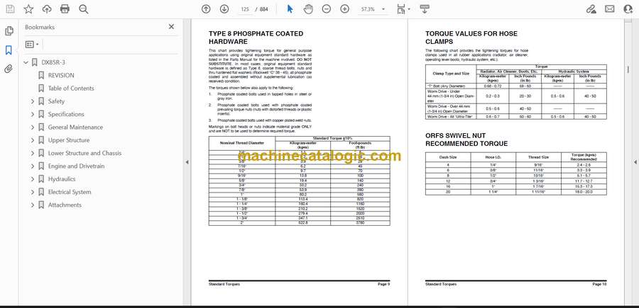
- Standard Torques
- Safety Instructions
- Torque Values for Standard Metric Fasteners
- Torque Values for Standard U.S. Fasteners
- Type 8 Phosphate Coated Hardware
- Torque Values for Hose Clamps
- ORFS Swivel Nut Recommended Torque
- Torque Values for Split Flanges
- Torque Wrench Extension Tools
- Torque Multiplication
- Other Uses for Torque Wrench Extension Tools
- Tightening Torque Specifications (Metric)
- Upper Structure
- Cabin
- Safety Instructions
- Cabin Identification
- Rollover Protective Structure (ROPS)
- Removal
- Installation
- Swing Bearing
- Safety Instructions
- Swing Bearing Maintenance
- Operating Recommendation
- Measuring Swing Bearing Axial Play
- Measuring Bearing Lateral Play
- Swing Bearing Basic Operation
- Disassembly
- Assembly
- Lower Structure and Chassis
- Track Assembly
- Safety Instructions
- Tracks
- Specification and Construction
- Track Tension
- Cleaning and Inspection (Wear Limits and Tolerances)
- Rubber Track
- Steel Track
- Track Frame Spring
- Idler
- Lower Roller
- Upper Roller
- Sprocket
- Idler
- Parts List
- Disassembly
- Assembly
- Lower Roller
- Steel Track
- Disassembly
- Assembly
- Rubber Track
- Disassembly
- Assembly
- Upper Roller
- Parts List
- Disassembly
- Assembly
- Track Removal and Installation
- Track Removal
- Track Installation
- Replacement of Rubber Tracks with Steel Tracks
- Replacement of Steel Tracks with Rubber Tracks
- Track Spring and Track Adjusting Cylinder
- Parts List
- Disassembly
- Reassembly
- Sprocket
- Engine and Drivetrain
- Engine (Stage 5/Tier 4)
- Safety Instructions
- General Service Information
- Component Identification
- Location of Labels
- Function of Major Engine Components
- Main Electronic Control Components and Features
- Function of Cooling System Components
- Installation Position Of Sensors
- Diesel Fuel
- Engine Oil
- Engine Coolant
- Specifications
- Principal Engine Specifications
- Engine Service Standards
- Tightening Torques for Standard Bolts and Nuts
- Periodic Maintenance
- Before You Begin Servicing
- Introduction
- Periodic Maintenance Schedule
- Periodic Maintenance Procedures
- Engine
- Before You Begin Servicing
- Introduction
- Cylinder Head Specifications
- Camshaft and Timing Gear Train Specifications
- Crankshaft and Piston Specifications
- Cylinder Block Specifications
- Special Torque Chart
- Special Service Tools
- Measuring Instruments
- Cylinder Head
- Measuring and Adjusting Valve Clearance
- Crankshaft and Camshaft Components
- EGR System
- Fuel System
- Before You Begin Servicing
- Fuel System Specifications
- Fuel System Diagram
- Fuel System Components
- Cooling System
- Before You Begin Servicing
- Introduction
- Cooling System Diagram
- Engine Coolant Pump Components
- Engine Coolant System Check
- Engine Coolant Pump
- Lubrication System
- Before You Begin Servicing
- Introduction
- Oil Pump Service Information
- Lubrication System Diagram
- Checking Engine Oil Pressure
- Trochoid Oil Pump
- Starter Motor
- Before You Begin Servicing
- Introduction
- Starter Motor Information
- Starter Motor Specifications
- Starter Motor Troubleshooting
- Starter Motor Components
- Starter Motor
- Alternator
- Before You Begin Servicing
- Introduction
- Alternator Specifications
- Alternator Troubleshooting
- Alternator Components
- Alternator Wiring Diagram
- Alternator
- Dynamo Component Location
- Dynamo Wiring Diagram
- Operation of Dynamo
- Testing of Dynamo
- Dynamo
- Electronic Control System
- Before You Begin Servicing
- Introduction
- Electronic Control System
- Diesel Particulate Filter (DPF)
- Electrical Wiring
- Electrical Wiring Precautions
- Electrical Wire Resistance
- Battery Cable Resistance
- Electrical Wire Sizes – Voltage Drop
- Conversion of AWG to European Standards
- Troubleshooting
- Special Service Tools
- Measured Value and Troubleshooting
- Quick Reference Table for Troubleshooting
- Failure Diagnosis Table
- Drive Coupling (Main Pump)
- Safety Instructions
- General Description
- Installation of Drive Coupling
- Installation Procedure
- Precaution
- Hydraulics
- Accumulator
- Safety Instructions
- General Description
- Center Joint (Swivel)
- Safety Instructions
- General Description
- Disassembly
- Reassembly
- Center Joint Assembly
- Cylinders
- Safety Instructions
- General Description
- Theory of Operation
- Parts List
- Special Tools and Materials
- Piston Nut
- Piston Jig
- Steel Bushing Jig
- Dust Wiper Jig
- Slipper Seal Jig
- Slipper Seal Straightening Jig
- Disassembly
- Reassembly
- Swing Device
- Safety Instructions
- Indication of Type
- Specifications
- Structure and Principle of Operation
- Parts List
- Principle of Operation
- Instructions Before Operation
- Inspection
- External Load at the End of Shaft
- Hydraulic Oil and Temperature Range
- Filter
- Installation and Piping
- Oil Filling and Air Ventilation
- Instructions Before Starting to Operate
- Troubleshooting
- General Instructions
- Examination of Hydraulic Motor
- Troubleshooting
- Disassembling and Assembling
- Tightening Torque of Bolts
- Necessary Tools
- Disassembly Procedure
- Maintenance Instructions
- Travel Device
- Safety Instructions
- Parts List
- Exploded Views of Hydraulic Gears
- General
- Configuration
- Features
- Structural Diagram of the Traveling System
- Structural Diagram of the Axial Piston Motor
- Operating Principle
- When Traveling
- When Counterbalance Operates
- When Brake Functions
- Operating Principle of Parking Brake
- 2 Speed Limiting Function
- Special Tools and Materials
- Standard Tools
- Bolts
- Equipment and Materials
- Manufacturing Tools
- Tightening Torque
- Weight Table
- Disassembly
- Preparations
- General Suggestions When Working
- Disassembly Procedure
- Service Preparations
- Seals
- Service Standards for Parts Subject to Wear
- Assembly
- Preparation
- General Suggestions When Working
- Assembly Procedure
- Performance Confirmation Test
- Required Measuring Devices
- Test Procedure
- Main Pump
- Safety Instructions
- A10 V(S)O pressure, Flow and Power Control DFLR 4
- Ports 4
- Description of Ports
- Circuit Diagram
- Function and Circuit Diagram
- Function Power Control
- Integrated Orifice and Damping Orifice
- Measurement of High-pressure
- Adjustment of DR, FR and LR – Control
- Adjustment of Power Control
- Hints for Assembling/Disassembling of the LR Valve
- Usage of DFLR – SO128 with LUDV Mobile Blocks
- DFLR-SO128, High-pressure Support and X-port
- DFLR – SO 128 Pilot Pressure Port X
- Section
- Spare Parts Kits
- Sealing Kits/Spare Parts Kits
- Sealing the Driveshaft
- Disassembly and Assembly of the Complete Unit
- Spare Parts Kit: A10 Control Valve DFR
- General Directions
- Spare Part Kit
- Fitting Note of the Control Valve – Devices
- A10 Control Valve DFR of Pump Size 140
- Disassembling and Cleaning the Control Valve
- List/Adjustment of Taper Roller Bearing Set
- List
- Taper Roller Bearing Initial Tension
- Testing and Set Up Instructions
- Tools/Auxiliary Tools/ Tightening Torques
- Installation of Pump Dump Orifice on A10
- A10, S0128 Regulator, Orifice of for Speed of Backstroking of Pump
- Main Control Valve
- Safety Instructions
- Functional Description, Section
- Assembly
- Abnormal Operation of the Actuators Connected to the Control Block
- Abnormal Machine Operation
- Visual Defects
- Fundamental Rules
- General Information Concerning Control Block Connection
- Removal/Installation of the SX 14 Control block
- General Recommendations
- Removal of the SX 14 Control Block
- Installation of the SX 14 Control Block
- Inlet and Outlet Elements Repair Procedures
- LS Pressure Relief Valve Replacement
- Flow Regulator Replacement
- Flow Regulator Filter Replacement
- “Open Center” Removal
- Hydraulic Operator Removal
- Hydraulic Control Housing Removal
- Control Block Disassembly/Assembly
- Preliminary Operations:
- Individual Pressure Compensator Removal
- Check Valve Removal
- Remote Control Valve (Work Lever/Joystick)
- Safety Instructions
- General Description
- Structure Diagram
- Performance Specification
- Hydraulic Pressure Circuit Diagram
- Tools and Materials
- Disassembly Method
- Assembly Method
- Travel Control Valve
- Safety Instructions
- General Description
- Performance Specification
- Hydraulic Pressure Circuit Diagram
- Maintenance
- Required Tool and Tightening Torque
- Maintenance Standard
- Disassembly
- Assembly
- Troubleshooting
- General Caution
- Troubleshooting and Resolution
- Dozer Valve
- Safety Instructions
- Structure Diagram
- Performance Specification
- Hydraulic Pressure Circuit Diagram
- Disassembly
- Assembly
- Pilot Supply Valve
- Safety Instructions
- General Description
- Functions and Operations
- Hydraulic Schematic
- Assembly Diagram and Tools Required
- Cautions During Disassembly and Reassembly
- Check Points and Solutions for Problems
- EPPR Valve
- Safety Instructions
- General Description
- Functions and Operations
- Hydraulic Schematic
- Reducing Pressure vs Current Characteristic
- Check Points and Solutions for Problems
- 2nd Auxiliary Valve (Option)
- Safety Instructions
- General Description
- Functions and Operations
- Quick Coupler Valve (Option)
- Safety Instructions
- General
- General Description
- Theory of Operation
- Hydraulic Circuit
- Caution for Installation
- Quick Coupler Operation
- Functions and Operations
- Hydraulic Schematic
- Check Points and Solutions for Problems
- Forced Regeneration Valve
- Safety Instructions
- Functions and Operations
- Hydraulic Schematic
- Check Points and Solutions for Problems
- Hydraulic Schematic
- Safety Instructions
- DX85R-3
- DX85R-3 (Arti Boom)
- Electrical System
- Electrical System (Stage 5/Tier 4)
- Safety Instructions
- Overview
- Electrical Supply System
- Engine Starting
- Start Operation
- After Start
- Engine Preheating System
- Engine Stop
- Charging System
- Instrument System
- Instrument Panel
- Function Check
- Operation
- User Menu
- User Menu – Access and Escape Methods
- Special Menu
- Circuit Diagram of Instrument Panel
- VCU
- Engine Control System
- Engine Control Dial
- Engine Control Circuit Diagram
- Automatic Deceleration Control (Auto Idle Control)
- Engine Overheat Protection System
- Hydraulic Oil Overheat Protection System
- Refrigerant Circulation
- Air-conditioning System Circuit Diagram
- Airflow Control
- Airflow Control Motor
- Blower Motor
- Coolant Flow Control Valve
- Temperature Level Control and Display
- Weight of R134a Gas Used in Machines
- Refrigerant System Repairs
- Refrigerant Safe Handling Procedures
- Repair and Replacement Procedure
- Refrigerant Recovery
- Vacuuming Refrigerant System
- Leakage Check
- Refrigerant Charging
- Inspecting System for Leakage
- Troubleshooting
- Refrigerant Pressure Check
- Electrical Schematic
- Safety Instructions
- DX85R-3 (Stage 5/Tier 4)
- Attachments
- Boom and Arm
- Safety Instructions
- Front Attachment Pin Specifications
- Front Attachment – Removal and Installation
- Arm Removal Procedure
- Boom Removal Procedure
- Installation
- Arm Installation Procedure
- Boom Installation Procedure
- Castle Nut Installation Procedure
- Start-up Procedures
- Bucket
- Safety Instructions
- Bucket Tooth Replacement
- Procedures of Bucket Tooth Replacement
- Bucket O-ring Replacement
- Bucket Attachment, Removal and Reversal
- Detaching the Bucket
- Attaching the Bucket
- Reversing the Bucket
Develon


