Develon DX255LC-7 Crawler Excavator Operation and Maintenance Manual (950106-02511DE) (1001 and Up)
Out on site this DX255LC-7 usually lives in the mud, dust, and rain, loading trucks, trenching, or hammer work all day. This operation and maintenance manual helps you set a rhythm: what to check every morning, what to service by hours, and what to inspect before you push it hard. Say you’re in peak season and the boom starts moving slower; instead of guessing, you’d trace the issue—oil level, filters, hydraulic temps—right off the routine laid out here so you don’t lose a day waiting on a tech.
Applications & Use Cases
- Set up a daily walk‑around so you check fluids, track tension, and leaks the same way every shift, then log anything that looks off.
- Plan your 250/500‑hour services so you can route hoses, change filters, and bleed the fuel system on your schedule, not when the machine quits.
- Use the startup and shutdown steps to test functions, verify warning lights, and isolate strange noises before they turn into big failures.
- Follow the lubrication charts to inspect pins and bushings, align attachments, and keep the front end tight during heavy digging.
- During long idle periods, use the storage and restart routines to check corrosion points, batteries, and seals so it’s ready when work picks up.
FAQ
Q: Is this manual searchable on a laptop or tablet, or is it just a flat scan?
A: It’s usually a searchable PDF, so you can jump to sections, use keywords, and zoom diagrams in the cab or trailer.
Q: Can I print just the service bits to keep in the toolbox?
A: Yes, you can typically print specific pages, then stick the daily checklists and service intervals right where your crew will see them.
Safety Note
Always bleed off hydraulic pressure and verify the engine can’t start before you put hands near any lines or moving parts.
Develon DX255LC-7 Crawler Excavator Index:
- DX255LC-7
- Revision
- Foreword
- Intended Use
- Engine and Emission Control System Maintenance
- Machine Capacity
- Attachments
- Product Identification Number (PIN)
- Component Serial Numbers
- Engine Identification
- Your Machine Serial Numbers
- Safety Messages
- Signal Words
- Other Signal Words
- EC DECLARATION OF CONFORMITY
- UK DECLARATION OF CONFORMITY
- Regulation (EU) 2017/654 Annex XV
- Engine operation and maintenance
- Malfunctions & Inducement
- DEVELON Fleet Management System General Information and Privacy Notice
- Safety
- Safety Decals
- Safety Decals With Text
- Safety Decals Without Text (No-Text)
- Information and Location for Safety Decals
- Information and Location for Safety Decals (Continued)
- 1. General Hazard (950205-03804)
- 2. Warning Tag – “Do Not Operate” (950205-03802B)
- 3. Keep Bystanders Away (950205-03803)
- 4. Hot Pressurized Fluid (950205-03781)
- 5. Rotating Fan / Hot Pressurized Fluid / Entanglement in Rotating Parts (950205-07530)
- 6. Battery Explosion (950205-03785)
- 7. Battery Disconnection (950205-03784)
- 8. Flying Debris or Objects (950205-03866)
- 9. Crush Hazard (950205-03805)
- 10. Pressurized Gas and Fluid (950205-03782)
- 11. Fall Hazard (950205-03783)
- 12. Hot Surface (950205-03777)
- 13. Emergency Exit (950205-03810)
- 14. Lifting Capacity Table / Electric Welding Attention / Hydraulic Breaker / ISO Control Pattern (950205-07527)
- 15. Impact Hazard (950205-03963)
- 16. Ultra Low Sulfur Diesel Fuel (950205-03864)
- 17. ROPS Warning (950205-03861)
- 18. Falling Object (950205-03786)
- 19. Fluorinated Greenhouse Gas (EU Only) (950205-06971, 950205-07796B)
- 20. Hydraulic Oil Check (950205-03965)
- 21. Coolant Level Check (950205-05395A)
- 22. Lift/Tie down (950205-03815)
- 23. Tie down (950205-03816)
- 24. Do Not Lift (950205-03570)
- 25. DEF (AdBlue®) (950205-01489A, 950205-07694B)
- 26. BHL Control Pattern (US Only) (950205-03868)
- 27. California Proposition 65 (US Only) (950205-07650)
- General
- Safe Operation is Operator’s Responsibility
- Know Your Machine
- Proper Work Tools and Attachments
- Pressurized Fluids
- Flying or Falling Objects
- Personal Protective Equipment (PPE)
- Correction of Machine Problems
- Crushing and Cutting
- Hot Coolant and Oils – Burn Prevention
- Fire and Explosion Prevention
- Maintenance
- Operation
- Electrical
- Hydraulic System
- Fueling
- Never Use Ether Starting Aids
- Welding and Grinding
- If a Fire Occurs
- Fire Extinguisher and First-aid Kit (Emergency Medical Kit)
- Electrical System and Electrical Shock
- Roll-over Protective Structure (ROPS)
- ROPS Certification
- Protecting Cabin from Flying or Falling Objects (If Equipped)
- Emergency Exit from Operator’s Station
- Regulation 8.35(2) of the Mines Safety and Inspection Regulations (1995)
- Transportation
- Obey State and Local Over-the-Road Regulations
- Loading and Unloading
- Transporting Machine
- Operation
- Before Engine Starting
- Work Site
- Mounting/Dismounting
- Cleaning
- Operator Station
- Seat Belt
- Visibility Information
- Restricted Visibility
- Mirror Adjustment
- Work Site Rules
- Boost Starting or Charging Engine Batteries
- Starting Engine with a Booster Cable
- Connecting Booster Batteries
- Disconnecting Booster Batteries
- Starting Engine
- Swinging or Traveling
- Lifting and Digging
- Operation on Slopes
- Towing
- Attachment
- Equipment Lowering with Engine Stopped
- Engine Stop
- Parking Machine
- Long Term Storage
- Before Storage
- During Storage
- After Storage
- Maintenance
- Warning Tag
- Cleaning
- Proper Tools and Clothing
- Disassembling Precautions
- Use of Lighting
- Fire and Explosion Prevention
- Burn Prevention
- Rubber That Contains Fluorides
- Rubber and Plastics
- Waste Hazardous to the Environment
- Check List After Fire
- Welding Repairs
- Preparation for Electrical Welding On Body Structure
- Warning for Counterweight and Front Attachment Removal
- Lock Inspection Covers
- Working on Machine
- Accumulator
- Compressed Air
- Track Tension Adjustments
- Supports and Blocking for Work Equipment
- High-pressure Lines, Tubes and Hoses
- Battery
- Battery Hazard Prevention
- Environment and Circumstances
- Work Site Areas Requiring Extra Caution
- Digging Under an Overhang
- Deep Digging
- Drop-off or Edge
- Poor Visibility
- Loose or Soft Ground
- High-voltage Cables
- Underground Operation
- Working in Water
- Working in Contaminated Environment
- Operation in Extreme Conditions
- Operation In Extreme Cold
- Operation in Extreme Heat
- Operation In Dusty and Sandy Areas
- Operation in Rainy or Humid Conditions
- Operation in Saltwater Areas
- Operation at High Altitudes
- Operation During Electrical Storms
- Exhaust Ventilation
- Ventilation for Enclosed Area
- Asbestos Information
- Silica Dust Information
- Disposal of Hazardous Materials
- Sound
- Vibration Information
- Hand/Arm Vibration Level
- Whole Body Vibration Level
- Guidelines for Use and Working Conditions of Earth-moving Machinery to Reduce Vibration Levels (ISO/TR 25398 Annex E)
- Operating Controls
- Component Locations
- Operator’s Area
- Operational Controls and Panels
- 1. Start/Stop Button
- 1-1.Starter Switch (If Equipped)
- 2. Smart Key
- 3. Air Conditioning and Heating Control Panel
- 4. 12V Power Socket
- 5. 24V Power Socket
- 6. USB Charger
- 7. Wiper Control Panel
- 8. Engine Speed Control Dial
- 9. After Treatment System Switch
- 10. Cabin Work Light Switch (If Equipped)
- 11. Light Switch
- 12. Travel Speed Selector Switch
- 13. Overload Warning Switch (If Equipped)
- 14. Buzzer Alarm Stop Switch (If Equipped)
- 15. Intelligent Floating Boom Switch (If Equipped)
- 16. Air Compressor Switch (If Equipped)
- 17. Warning Light Switch (If Equipped)
- 18. Mirror Heater (If Equipped)
- 19. Fine Swing Switch
- 20. Quick Coupler Switch (If Equipped)
- 21. Auxiliary Mode Switch
- 22. Emergency Start Mode Switch
- 23. One Touch Deceleration Button
- 24. Horn Button
- 25. Rotating Switch (If Equipped)
- 26. Breaker/Booster Button
- 27. Joystick One Touch Function Button
- 28. Shear Switch (If Equipped)
- 29. Micro Phone (If Equipped)
- 30. Display Monitor
- 31. Around View Monitoring (AVM) Monitor (If Equipped)
- 32. Photo Sensor
- 33. Hour Meter
- 34. Safety Lever
- Display Monitor
- Functional Check
- Setting a Password
- 1. Fuel Gauge
- 2. DEF (AdBlue®) Level Gauge
- 3. Engine Coolant Temperature Gauge
- 4. Hydraulic Oil Temperature Gauge
- 5. Tachometer
- 6. Audio Display
- 7. Main Warning Lamp
- 8. Digital Clock
- 9. Favorites Button
- 10. Main Information Selector Button
- 11. Main Information Indicator
- 12. Power Mode Selector Button
- 13. Power Mode Indicator
- 14. Operating Mode/Flow Setting Selector Button
- 15. Auto Idle Selector Button
- 16. Menu Selector Button
- 17. Back Button
- 18. Camera Mode Selector / ESC Button
- 19. Jog Switch
- 20. Mode Symbol Display
- 21. Indicator Display
- 22. Display Warning Symbols
- Warning Pop-Up Messages
- User Menu
- User Menu – Access and Escape Methods
- Access Method
- Exiting/Escaping Menus
- User Menu
- Around View Monitoring (AVM) System
- Operating Conditions and Instructions
- Screen Components and View Modes
- Displaying Outlines of the Vehicle Area
- Proximity Alarm System
- Sensor Locations
- Sensor Operating Conditions and Settings
- Sensor Alarm Setting
- Operating Range and Display
- Sensor Non-Activation Conditions
- Sensor Management Information
- Heater and Air Conditioner Control Panel
- Location of Controls and Vents
- Control Panel
- 1. Automatic Temperature Control Button
- 2. Off Button
- 3. Temperature Control Button
- 4. Mode Selector Button
- 5. Air Inlet Selector Button
- 6. Fan Speed Selector Buttons
- 7. Air Conditioner Button
- 8. Defroster Button
- 9. LCD Display
- Memory Function
- Additional Operating Instructions
- Miscellaneous Electrical Devices
- Cabin Light
- Safety Lever
- Circuit Breaker (50A, 80A)
- Fuse Boxes
- DAB (Digital Audio Broadcasting) Audio
- Seat Adjustment
- 1. Forward/Backward Adjustment
- 2. Adjusting Height of Seat and Depth of Cushion
- Seat Height
- Forward Tilt
- Cushion Slide
- 3. Reclining Position Adjustment
- 4. Headrest
- 5. Lumbar Support Adjustment
- 6. Seat Heater Switch
- 6-1. Heating/Ventilation Switch (If Equipped)
- 7. Left and Right Control Stand Adjustment
- 8. Left and Right Control Stand Height Adjustment
- 9. Adjusting Height/Angle of Armrest
- Seat Belt
- Seat Belt Locking and Unlocking
- Engine Emergency Stop Switch
- Emergency Exit Glass Breaking Tool
- Miscellaneous Convenience Devices
- Ceiling Cover
- Opening Ceiling Cover
- Closing Ceiling Cover
- Front Windows
- Front Upper Window
- Front Bottom Window
- Door Side Latch
- Cabin Storage Compartments
- Sun Visor
- Front Window Sun Visor
- Ceiling Door Sun Visor (If Equipped)
- Rear Window Sun Visor (If Equipped)
- Sunglasses Case
- Cup Holder
- Storage Box
- Miscellaneous Access Covers and Doors
- Side Door
- Storage Box Door
- Engine Hood
- Air Gun and Compressor (If Equipped)
- Air Gun
- How to Use Air Compressor
- How to Connect Air Gun
- Connecting the Air Gun in the Cabin
- Connecting the Air Gun Directly to the Air Compressor Motor in the Battery Box
- Operation
- To Operate a New Excavator
- Starting and Stopping Engine
- Inspection Before Starting Engine
- Walk Around Checks
- Checks Before Starting Engine
- Operational Checks Before Starting Engine
- Engine Start
- Diesel Heater (If Equipped)
- Overview
- Operating and Setting
- Hydraulic System Warm-up
- Hydraulic System Warm-up – Cold Weather
- Stopping Engine
- Checks and Maintenance After Stopping Engine
- Wait to Disconnect Indicator
- Safety Lever
- Travel
- Automatic Travel Speed Control
- Travel Control Lever Operation
- General Travel Instructions
- Straight Travel Pedal (If Equipped)
- Operating Instructions
- Engine Speed Control
- Emission Control System
- Low Level DEF
- DEF Quality / Dosing Error
- The Value of the Carbon Dioxide (CO2) Emissions
- Inducement
- After Treatment System
- Active Regeneration
- Manual (Forced) Regeneration
- Mode Selection
- Power Mode
- Work Mode
- Auto Idle Mode
- Boost Mode
- Change Machine Control Pattern By Selector Valve (If Equipped)
- Work Levers (Joysticks) (ISO Pattern)
- Left-hand Work Lever (Joystick) (Figure 69 and Figure 70)
- Right-hand Work Lever (Joystick) (Figure 69 and Figure 72)
- Work Levers (Joysticks) (BHL Pattern)
- Left-hand Work Lever (Joystick) (Figure 69 and Figure 73)
- Right-hand Work Lever (Joystick) (Figure 69 and Figure 74)
- Intelligent Floating Boom Control (If Equipped)
- Intelligent Floating Boom Mode
- Operating a Breaker
- Truck Loading
- Two-Piece Boom (If Equipped)
- Smart Power Control (SPC)
- Operating Precautions
- Working in Water
- Escaping From Mud
- Track On One Side Stuck
- Tracks On Both Sides Stuck
- Parking Excavator
- Towing Procedure
- Attachments
- Bucket Replacement and Reversal
- Replacement
- Reversal (If Applicable)
- Hydraulic Attachments (If Equipped)
- Breaker Operation
- Selection of Hydraulic Breaker
- Hydraulic Hoses and Tubing for Breaker
- Breaker Operating Precautions
- To Activate Breaker
- Shear Operation
- One-Way/Two-Way Valve Operation
- Activating Shear with Pedal Valve
- Activating Breaker with Pedal Valve
- Stopper Positions
- Rotating Operation
- Quick Coupler Operation
- To Engage Attachment
- To Release Attachment
- Lifting Objects
- Lifting Unknown Weight
- Lifting Known Weight
- Pick and Carry
- Lifting Objects with Quick Coupler
- Equipment Lowering with Engine Stopped
- Machine without a Boom Lock Valve
- Machine with a Boom Lock Valve
- Inspection, Maintenance and Adjustment
- Maintenance Information
- Operational Hour Meter Reading
- DEVELON Genuine Replacement Parts
- DEVELON Genuine Lubricants
- Windshield Washer Fluid
- Fresh and Clean Lubricants
- Check Drained Oil and Used Filter
- Check for Leaks in Fuel System
- Fuel Strainer
- Welding Instructions
- Do Not Drop Things Inside Machine
- Dusty Work Site
- Avoid Mixing Lubricants
- Locking Inspection Covers
- Check for Leaks in Hydraulic System
- Hydraulic System – Air Bleeding
- Hydraulic Hose Installation
- Checks After Inspection and Maintenance Works
- Coolant, Oil, Fuel – Drain and Change
- Safety Precautions
- Machine Setup Position for Maintenance
- Handling Oil, Fuel, DEF (AdBlue®), Coolant
- Oil
- Fuel
- DEF (AdBlue®)
- Engine Oil
- Grease
- Coolant and Water for Dilution
- Filters
- Electrical System Maintenance
- Recommend Fuel, Coolant, and Lubricant
- Lubrication
- Symbols for “Lubrication and Service Chart”
- Lubrication and Service Chart
- Hydraulic Oil and Filter Service Intervals
- Fluid Capacities
- Table of Recommended Lubricants
- Maintenance Intervals
- 10 Hour / Daily Service
- Boom, Arm and Front Attachment Pins – Lubricate
- Engine Oil Level – Check
- Hydraulic Oil Level – Check
- Fuel Level – Check
- DEF (AdBlue®) Tank Level- Check
- Pre Fuel Filter and Water Separator – Check
- Swing Reduction Gear Oil Level – Check
- Dust Net – Clean
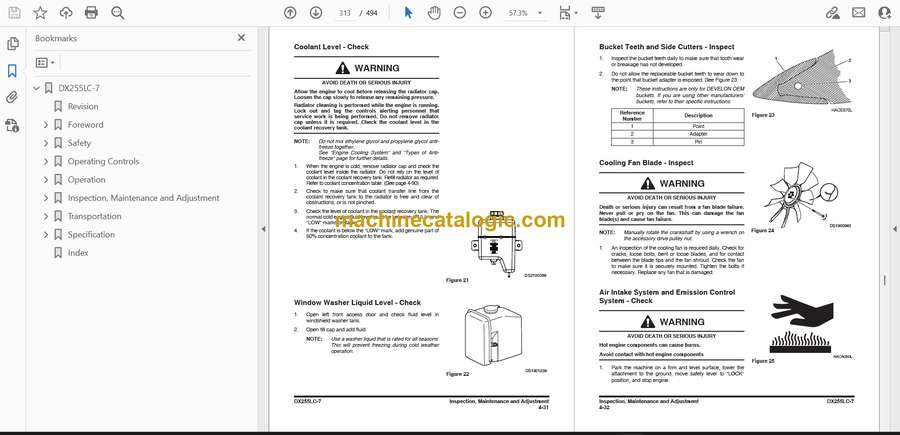
- Coolant Level – Check
- Window Washer Liquid Level – Check
- Bucket Teeth and Side Cutters – Inspect
- Cooling Fan Blade – Inspect
- Air Intake System and Emission Control System – Check
- Seat Belt – Inspect
- AVM (Around View Monitoring system) – Check
- Mirrors – Check
- Structure – Inspect
- All Switches and Travel Alarm (If Equipped) – Check
- Safety Lever – Check
- Inspection and Maintenance of the Safety Lever
- Exterior Lights, Horn, Control Console Indicator, Gauge Panel – Check
- Overall of Engine Condition – Check
- All Controls and Linkages – Check
- 50 Hour / Weekly Service
- Perform All Daily Service Checks
- Arm and Bucket Joint Pins – Lubricate
- Dozer Blade Pin – Lubricate
- Swing Bearing – Lubricate
- Fuel Tank Water and Sediment – Drain
- Air Compressor and Tank – Check
- Engine Fan Belt – Check
- Track Assemblies (Links, Shoes, Rollers, Idlers) – Inspect
- 250 Hour / Monthly Service
- Perform All Daily and 50 Hour Service Checks
- Boom and Arm Joint Pins (One Piece Boom) – Lubricate
- Boom and Arm Joint Pins (Two – Piece Boom) – Lubricate
- Engine Fan and Alternator Belts – Check
- Breaker Filter (If Equipped) – Replace
- Hydraulic Oil Return Filter – Replace
- Pilot Filter – Replace
- Pin and Bushings of the Front End Attachment – Inspect
- Battery Fluid – Check
- Bolts and Nuts – Inspect
- Fuel System Hose Clamps – Inspect
- 500 Hour / 3 Month Service
- Perform All Daily, 50 and 250 Hour Service Checks
- Track Spring – Check
- Swing Gear and Pinion – Lubricate
- Engine Oil and Filter – Replace
- Air-Conditioning Outer Filter – Clean
- Air-Conditioning Inner Filter – Clean
- Cooling System – Clean
- Air Cleaner Outer Filter – Clean
- Final Drive Gear Oil – Check
- Air Compressor Filter (If Equipped) – Clean
- Final Drive Gear Oil – Change
- Swing Reduction Gear Oil – Change
- 1,000 Hour / 6 Month Service
- Perform All Daily, 50, 250 and 500 Hour Service Checks
- Swing Reduction Gear – Lubricate
- Hydraulic Oil Tank Breather Filter – Replace
- Hydraulic Oil Return Filter – Replace
- Pre Fuel Filter – Replace
- Main Fuel Filter – Replace
- Pilot Filter – Replace
- Final Drive Gear Oil – Change
- Swing Reduction Gear Oil – Change
- Air-Conditioning Outer Filter – Replace
- Air-Conditioning Inner Filter – Replace
- Fuel Cap Filter – Replace
- Check and Adjust Engine**
- 2,000 Hour / Yearly Service
- Perform All Daily, 50, 250, 500 and 1,000 Hour Service Checks
- Air Cleaner Outer and Inner Filter – Replace
- Coolant – Change
- Hydraulic Oil and Suction Filter – Replace
- Alternator and Starter** – Check
- Rubber Antivibration Shock Mounts – Check
- Perform and Record Results of Cycle Time Tests
- Inspect Machine to Check for Cracked or Broken Welds or other Structural Damage
- Adjust Valve Clearance** – Check
- Head Bolt Torques – Check
- 4,000 Hour / Biennial Service
- Major Parts – Periodic Replacement
- 4,500 Hour / Biennial Service
- DEF (AdBlue®) Filter – Replace
- DEF (AdBlue®) Breather Filter – Replace
- 8,000 Hour / 4 Year Service
- 12,000 Hour / 6 Year Service
- Hose In-service Lifetime Limit (European Standard ISO 8331 and EN982 (CEN))
- Air-Conditioning System
- Check Control Panel
- Check Air Conditioner Hoses
- Check Condenser
- Check Magnetic Clutch
- Bucket
- Bucket Tooth Replacement
- Bucket O-ring Replacement
- Electrical System
- Battery
- Batteries in Cold Weather
- Inspection of Battery Electrolyte Level
- Check Charging State
- Check Battery Terminals
- Battery Replacement
- Fuses
- Fuse Boxes
- Fuse Identification
- Engine Cooling System
- General
- Antifreeze Concentration Tables
- Table of Standards for Allowed Tap Water
- Fuel Transfer Pump (If Equipped)
- Handling of Accumulator
- Track Tension
- Venting and Priming Hydraulic System
- Main System Pump
- Hydraulic Cylinders
- Swing Motor
- Travel Motor
- General Venting
- Maintenance in Special Conditions
- Transportation
- Loading and Unloading
- Warning for Counterweight and Front Attachment Removal
- Counterweight
- Lifting Machine
- Specification
- Standard Specification
- Overall Dimensions
- One – Piece Boom
- Two – Piece Boom
- Disassembled Parts, Dimension and Weight
- Ground Pressure
- Digging Force
- Arm – Tearout Force
- Bucket – Breakout Force
- Working Range
- One – Piece Boom
- Two – Piece Boom
- Excavator Rated Lift Capacity Tables
- Approximate Weight of Workload Materials
- Index
Develon


