Develon DX225LCE Crawler Excavator Operation and Maintenance Manual
This DX225LCE usually lives in the rough stuff—demo sites, drainage work, pipe trenches, quarry faces—anywhere you’re swinging big loads all day. This operation and maintenance manual helps you set a rhythm: what to trace, check, and inspect each day, what to service at longer intervals, and how to keep the machine predictable when the season gets busy. Say you’re in the middle of a big dig and a swing alarm pops up; with this, you can quickly verify the basics, isolate where to look first, and decide if you can finish the shift or need to shut it down.
Applications & Use Cases
- Set up a daily walkaround so you trace leaks, check track tension, and inspect hoses before they become downtime.
- Plan your service intervals so you don’t skip filters and fluids, then wonder why it won’t build power under load.
- Use it to bleed and test the fuel and hydraulic systems properly after a filter change or hose repair.
- Verify correct attachment changes so you align pins, route hoses right, and don’t blow a line the first time you curl in.
- Troubleshoot odd behavior—slow boom, noisy pump—by following step‑by‑step checks instead of just guessing.
FAQ
Q: Is this a PDF I can search on my laptop or tablet?
A: Yes, it’s typically a searchable PDF, so you can jump to sections and keywords instead of flipping pages.
Q: Can I print just the pages I need for the jobsite?
A: You usually can; most folks print the service charts and key procedures, stick ’em in a binder, and keep the full file on a device.
Safety Note
Always lower the attachment to the ground, relieve hydraulic pressure, and remove the key before you test, inspect, or service anything on this machine.
Develon DX225LCE Crawler Excavator Index:
- DX225LCE Excavator
- Table of Contents
- Foreword
- Intended Use
- Machine Capacity
- Attachments
- Product Identification Number (PIN)
- Machine Serial Numbers
- Safety Messages
- Signal Words
- Other Signal Words
- Safety
- Safety Decals
- Safety Decals With Text
- Safety Decals Without Text (No-Text)
- Information and Location for Safety Decals
- Information and Location for Safety Decals (Continued)
- 1. General Hazard (950205-03804)
- 2. Warning Tag – “Do Not Operate” (950205-03802B)
- 3. Keep Bystanders Away (950205-03803)
- 4. Rotating Fan / Hot Pressurized Fluid / Entanglement in Rotating Parts (950205-07530)
- 5. Hot Pressurized Fluid (950205-03781)
- 6. Battery Explosion (950205-03785)
- 7. Battery Disconnection (950205-03784)
- 8. Flying Debris or Objects (950205-03866)
- 9. Crush Hazard (950205-03805)
- 10. Pressurized Gas and Fluid (950205-03782)
- 11. Fall Hazard (950205-03783)
- 12. Hot Surface (950205-03777)
- 13. Emergency Exit (950205-03810)
- 14. ROPS Warning (If Equipped) (950205-03861)
- 15. ISO Control Pattern / Hydraulic Breaker / Electric Welding Attention (950205-07527)
- 16. Falling Object (950205-03786)
- 17. Hydraulic Oil Check (950205-06281, 950205-03965, 950205-06282)
- 18. Lift/Tie down (950205-03815)
- 19. Tie down (950205-03816)
- 20. Do Not Lift (950205-03570)
- General
- Safe Operation is Operator’s Responsibility
- Know Your Machine
- Proper Work Tools and Attachments
- Pressurized Fluids
- Flying or Falling Objects
- Personal Protective Equipment (PPE)
- Correction of Machine Problems
- Crushing and Cutting
- Hot Oils – Burn Prevention
- Fire and Explosion Prevention
- Maintenance
- Electrical
- Hydraulic System
- Welding and Grinding
- If a Fire Occurs
- Fire Extinguisher and First-aid Kit (Emergency Medical Kit)
- Roll-over Protective Structure (ROPS) (If Equipped)
- ROPS Certification
- Protecting Cabin from Flying or Falling Objects (If Equipped)
- Emergency Exit from Operator’s Station
- Transportation
- Obey State and Local Over-the-Road Regulations
- Loading and Unloading
- Transporting Machine
- Operation
- Before Motor Starting
- Work Site
- Mounting/Dismounting
- Cleaning
- Operator Station
- Seat Belt
- Visibility Information
- Starting Motor
- Swinging or Traveling
- Lifting and Digging
- Operation on Slopes
- Towing
- Attachment
- Equipment Lowering with Motor Stopped
- Motor Stop
- Parking Machine
- Long Term Storage
- Before Storage
- During Storage
- After Storage
- Maintenance
- Warning Tag
- Cleaning
- Proper Tools and Clothing
- Disassembling Precautions
- Use of Lighting
- Fire and Explosion Prevention
- Burn Prevention
- Rubber That Contains Fluorides
- Rubber and Plastics
- Waste Hazardous to the Environment
- Check List After Fire
- Welding Repairs
- Preparation for Electrical Welding on Body Structure
- Warning for Counterweight and Front Attachment Removal
- Lock Inspection Covers
- Working on Machine
- Accumulator
- Compressed Air
- Track Tension Adjustments
- Supports and Blocking for Work Equipment
- High-pressure Lines, Tubes and Hoses
- Battery
- Battery Hazard Prevention
- Environment and Circumstances
- Work Site Areas Requiring Extra Caution
- Digging Under an Overhang
- Deep Digging
- Drop-off or Edge
- Poor Visibility
- Loose or Soft Ground
- High-voltage Cables
- Underground Operation
- Working in Water
- Working in Contaminated Environment
- Operation in Extreme Conditions
- Operation In Extreme Cold
- Operation in Extreme Heat
- Operation In Dusty and Sandy Areas
- Operation in Rainy or Humid Conditions
- Operation in Saltwater Areas
- Asbestos Information
- Silica Dust Information
- Disposal of Hazardous Materials
- Sound
- Operating Controls
- Component Locations
- Operator’s Area
- Operational Controls and Panels
- 1. Starter Switch
- 2. Engine Speed Control Dial
- 3. Power Socket For 12V
- 4. Power Socket For 24V
- 5. Air Conditioning and Heating Control Panel
- 6. Audio Control Panel
- 7. Wiper Control Panel
- 8. Travel Speed Selector Switch
- 9. Light Switch
- 10. Breaker/Boost/Shear Selector Switch (If Equipped)
- 11. Auxiliary Mode Switch
- 12. Seat Warmer Switch (If Equipped)
- 12-1. Power Mode Selector Switch
- 13. Cabin Work Light Switch (If Equipped)
- 14. Warning Light Switch (If Equipped)
- 15. Travel/Swing Alarm Switch (If Equipped)
- 16. Overload Warning Switch (If Equipped)
- 17. Quick Coupler Switch (If Equipped)
- 18. Instrument Panel/Display Monitor
- 19. Horn Button
- 20. Breaker/Booster Button
- 21. Rotating Switch (If Equipped)
- 22. Shear Switch (If Equipped)
- 23. Safety Lever
- 24. Photo Sensor
- 25. Hour Meter
- 26. Breaker Electric Pedal (If Equipped)
- 27. Wireless Controller
- Instrument Panel (Non ROPS)
- Functional check
- Password Activated
- 1. Fuel Gauge
- 2. Coolant Temperature Gauge
- 3. Hydraulic Oil Temperature Gauge
- 4. Multifunction Gauge and Graphic Information Area
- 5. Digital Clock
- 6. Charge Warning
- 7. Engine Oil Pressure Warning
- 8. Coolant Temperature Warning
- 9. Engine Check Warning
- 10. Preheating Indicator
- 11. Work Light Indicator
- 12. Warning Light
- Multifunction Gauge and Graphic Information
- Communication Indicator
- Communication Error Warning
- Battery Voltage
- Front Hydraulic Pump Pressure
- Rear Hydraulic Pump Pressure
- Abnormal State Warning Symbols
- Examples of Warning Display
- 1. Hydraulic Oil Overheat Warning
- 2. Return Filter Clogged Warning
- 3. Overload Warning (If Equipped)
- Mode Selector Buttons
- 1. Power Mode Selector Button
- 2. Economy Mode Selector Button
- 3. Auto Idle Selector Button
- 4. Flow Control Button
- Wireless Controller
- 1. Motor Start Button (START)
- 2. Motor Stop Button (STOP)
- 3. Emergency Stop Button (EMERGENCY STOP)
- 4. Distance Warning Lamp
- 5. Turn Warning Lamp
- 6. Power Cutoff Lamp
- Setting Main Menu
- 1. Up Arrow Button
- 2. Down Arrow Button
- 3. Display Selector Button (ESC – Escape)
- 4. Selection Button
- Display Selection and Escaping
- Display Selection
- ESC Button
- Main Menu
- Language
- Set Clock
- Setting Method
- ’00’ Minute Setting
- Filter/Oil Info
- Menu Display Order and Icon Explanation
- Filter/Oils Operating Hour Reset
- Adjust Display
- Set Password (Lock and Unlock)
- Flow Control
- Adjusting Flow Rate
- Escape
- Operation Selection Display
- Power Mode Selection
- Standard Mode Selection
- Economy Mode Selection
- Auto Idle Selection
- Power Boost Selection
- Breaker Selection
- Shear Selection
- Quick Coupler Operation Selection (If Equipped)
- Camera Mode Selector Button
- Camera mode selector button (If Equipped)
- Display Monitor (ROPS)
- Functional Check
- Password Activated
- 1. Fuel Gauge
- 2. Coolant Temperature Gauge
- 3. Hydraulic Oil Temperature Gauge
- 4. Multifunction Gauge and Graphic Information Area
- 5. Digital Clock
- 6. Display Warning Symbols
- 7. Warning Light
- 8. Function Buttons
- 9. Selector Function Display
- Launch Menu
- Warning Pop-up Window
- Warning Pop-up Windows List
- Wireless Controller
- 1. Motor Start Button (START)
- 2. Motor Stop Button (STOP)
- 3. Emergency Stop Button (EMERGENCY STOP)
- 4. Distance Warning Lamp
- 5. Turn Warning Lamp
- 6. Power Cutoff Lamp
- User Menu
- User Menu – Access and Escape Methods
- Access Method
- Escape Method
- User Menu
- Switch Operation Indication
- Heater and Air Conditioner Control Panel
- Location of Controls and Vents
- Control Panel
- 1. Automatic Temperature Control Button
- 2. Off Button
- 3. Temperature Control Button
- 4. Temperature Unit Selector Button
- 5. Mode Selector Button
- 6. Air Inlet Selector Button
- 7. Fan Speed Selector Buttons
- 8. Air Conditioner Button
- 9. Defroster Button
- 10. LCD Display
- Memory Function
- Additional Operating Instructions
- Stereo
- Miscellaneous Electrical Devices
- Cabin Light
- Safety Lever
- Circuit Breaker (30A, 60A)
- Fuse Boxes
- Seat Adjustment (Non ROPS)
- Mech. Suspension Seat
- Forward/Backward Adjustment
- Seat Tilt and Height Adjustment
- Suspension Adjustment
- Reclining Position Adjustment
- Armrest Angle Adjustment
- Lumbar Support Adjustment
- Headrest
- Seat Back-pocket
- Left and Right Control Stand Adjustment
- Left and Right Control Stand Height Adjustment
- Air Suspension Seat
- Forward/Backward Adjustment
- Seat Tilt and Height Adjustment
- Air Suspension Adjustment
- Reclining Position Adjustment
- Armrest Angle Adjustment
- Lumbar Support Adjustment
- Headrest
- Seat Back-pocket
- Heating the Operator’s Seat
- Seat Adjustment (ROPS)
- Air Suspension Seat
- Forward/Backward Adjustment
- Adjusting Height of Seat and Depth of Cushion
- Reclining Position Adjustment
- Headrest
- Lumbar Support Adjustment
- Seat Heater Switch
- Left and Right Control Stand Adjustment
- Left and Right Control Stand Height Adjustment
- Adjusting Height/Angle of Armrest
- Seat Belt
- Seat Belt Locking and Unlocking
- Miscellaneous Convenience Devices
- Ceiling Cover
- Opening Ceiling Cover
- Closing Ceiling Cover
- Front Windows
- Front Upper Window
- Front Bottom Window
- Door Side Latch
- Cabin Storage Compartments
- Sun Visor
- Front Window Sun Visor
- Ceiling Door Sun Visor (If Equipped)
- Emergency Glass Breaking Tool
- Sunglasses Case
- Cup Holder
- Miscellaneous Access Covers and Doors
- Side Door
- Battery Box Door
- Motor Cover
- Operation
- To Operate a New Excavator
- Starting and Stopping Motor
- Inspection Before Starting Motor
- Walk Around Checks
- Checks Before Starting Motor
- Operational Checks Before Starting Motor
- Motor Start
- Hydraulic System Warm-up
- Hydraulic System Warm-up – Cold Weather
- Stopping Motor
- Check and Confirmation After Stopping Motor
- Safety Lever
- Travel
- Automatic Travel Speed Control
- Travel Control Lever Operation
- General Travel Instructions
- Work Levers (Joysticks) (ISO Pattern)
- Left-hand Work Lever (Joystick) (Figure 21 and Figure 22)
- Right-hand Work Lever (Joystick) (Figure 21 and Figure 24)
- Operating Precautions
- Working in Water
- Escaping From Mud
- Track On One Side Stuck
- Tracks On Both Sides Stuck
- Parking Excavator
- Towing Procedure
- Hydraulic Attachments (If Equipped)
- One-way/Two-way Valve
- Activating Shear with Pedal Valve
- Stopper Positions
- Rotating Pedal Valve
- Attachment Rotating by Using the Pedal Valve
- Locking the Pedal
- Attachment Rotation Using the Left-hand Work Lever (Joystick)
- Quick Coupler Operation
- To Engage Attachment
- To Release Attachment
- Lifting Objects
- Lifting Unknown Weight
- Lifting Known Weight
- Pick and Carry
- Lifting Objects with Quick Coupler
- Inspection, Maintenance and Adjustment
- Maintenance Information
- Operational Hour Meter Reading
- DOOSAN Genuine Replacement Parts
- DOOSAN Genuine Lubricants
- Windshield Washer Fluid
- Fresh and Clean Lubricants
- Check Drained Oil and Used Filter
- Welding Instructions
- Do Not Drop Things Inside Machine
- Dusty Work Site
- Avoid Mixing Lubricants
- Locking Inspection Covers
- Hydraulic System – Air Bleeding
- Inspecting Electrical Systems
- Hydraulic Hose Installation
- Checks After Inspection and Maintenance Works
- Safety Precautions
- Machine Setup Position for Maintenance
- Handling Oil
- Electrical System Maintenance
- Recommend Lubricant
- Lubrication and Service Chart
- Lubrication and Service Chart
- Fluid Capacities
- Table of Recommended Lubricants
- Maintenance Intervals
- 10 Hour / Daily Service
- Grease Boom, Arm and Front Attachment Pins (for first 100 hours)
- Check for Leaks in Hydraulic System
- Check Level of Hydraulic Oil Tank
- Check Oil Level of Swing Reduction Gear
- Clean Dust Net in Front of Oil Cooler and Intercooler
- Check Level of Window Washer Liquid
- Inspect the Bucket Teeth and Side Cutters for Signs of Wear
- Inspect Cooling Fan Blade
- Inspect Seat Belt for Proper Operation
- Inspect Mirrors for Damage and Adjust and Clean as Required
- Inspect the Structure for Cracks and Faulty Welds
- Check Operation of All Switches and Travel Alarm (If Equipped)
- Check the Operation of Safety Lever
- Inspection and Maintenance of the Safety Lever
- Check the Operation of All Exterior Lights, Horn and Control Console Indicator and Monitor Lights
- Check Operation of All Controls
- 50 Hour / Weekly Service
- Perform All Daily Service Checks
- Grease Arm and Bucket Joint Pins
- Grease Swing Bearing
- Inspect the Track Assemblies for Proper Tension and Loose, Worn or Damaged Parts (Links, Shoes, Rollers, Idlers)
- 250 Hour / Monthly Service
- Perform All Daily and 50 Hour Service Checks
- Grease Boom and Arm Joint Pins
- Clean Air-Conditioning Outer Filter (Non ROPS)
- Clean Air-Conditioning Outer Filter (ROPS)
- Replace Hydraulic Oil Return Filter (After First 250 Hours)
- Change Pilot Filter (After First 250 Hours)
- Inspect Pins and Bushings of the Front End Attachments for Signs of Wear
- Inspect for Any Loose or Missing Nuts and Bolts
- 500 Hour / 3 Month Service
- Perform All Daily, 50 and 250 Hour Service Checks
- Grease Swing Gear and Pinion
- Change Air-Conditioning Outer Filter (Non ROPS)
- Change Air-Conditioning Outer Filter (ROPS)
- Check and Clean Air-conditioning Inner Filter
- Clean Radiator, Oil Cooler, Intercooler and Air Conditioner Condenser Core
- Check Oil Level in Travel Reduction Gear (One on Each Side of Unit)
- Change Oil in Travel Reduction Gear (One on Each Side of Unit) (After First 500 Hours)
- Change Swing Reduction Gear Oil (Drain and Refill After First 500 Hours)
- 1,000 Hour / 6 Month Service
- Perform All Daily, 50, 250 and 500 Hour Service Checks
- Grease Swing Reduction Gear
- Change Hydraulic Oil Tank Breather Filter
- Replace Hydraulic Oil Return Filter
- Change Pilot Filter
- Change Oil in Travel Reduction Gear (One on Each Side of Unit)
- Change Swing Reduction Gear Oil
- Change Air-conditioning Inner Filter
- 1,500 Hours / 9 Month Service
- Perform All Daily, 50, 250, 500 and 1,000 Hour Service Checks
- Grease Motor (Pump Side)
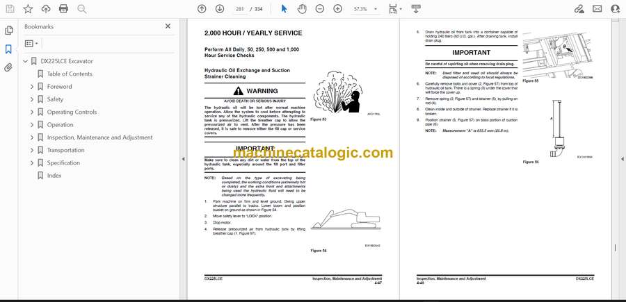
- 2,000 Hour / Yearly Service
- Perform All Daily, 50, 250, 500 and 1,000 Hour Service Checks
- Hydraulic Oil Exchange and Suction Strainer Cleaning
- Perform and Record the Results of the Cycle Time Tests
- Inspect Machine to Check for Cracked or Broken Welds or other Structural Damage
- Check, Adjust Valve Clearance **
- Check Head Bolt Torques
- 2,500 Hours / 15 Month Service
- Perform All Daily, 50, 250, 500, 1,000, 1,500 and 2,000 Hour Service Checks
- Grease Motor (Fan Side)
- 4,000 Hour / Biennial Service
- Major Parts – Periodic Replacement
- 12,000 Hour / 6 Year Service
- Hose In-service Lifetime Limit (European Standard ISO 8331 and EN982 CEN)
- Air-Conditioning System
- Check Control Panel
- Check Air Conditioner Hoses
- Check Condenser
- Check Magnetic Clutch
- Bucket
- Bucket Tooth Replacement
- Bucket O-ring Replacement
- Electrical System
- Battery
- Batteries in Cold Weather
- Inspection of Battery Electrolyte Level
- Check Charging State
- Check Battery Terminals
- Battery Replacement
- Fuses
- Fuse Boxes
- Fuse Identification
- Handling of Accumulator
- Track Tension
- Venting and Priming Hydraulic System
- Main System Pump
- Hydraulic Cylinders
- Swing Motor
- Travel Motor
- General Venting
- Maintenance in Special Conditions
- Transportation
- Loading and Unloading
- Warning for Counterweight and Front Attachment Removal
- Lifting Machine
- Specification
- Standard Specification
- Overall Dimensions
- Disassembled Parts, Dimension and Weight
- Digging Force
- Working Range
- Excavator Rated Lift Capacity Tables
- Approximate Weight of Workload Materials
- Index
Develon


