Format: PDF (Printable Document)
File Language: English
File Pages: 218
File Size: 119.78 MB (Speed Download Link)
Brand: Liebherr
Model: LTM 1100-5.2 Mobile Crane
Components: Carrier + Superstructure
Serial No: SN 093049
Date: 2023
Type of Document: Technical Information & BMK Components Manual
$ 80
The Liebherr LTM 1100-5.2 Mobile Crane earns its keep on sites where you’re lifting serious loads all day, so knowing exactly where every relay, valve, and sensor sits saves real money in downtime. The people who usually reach for the BMK / component identification manual are techs chasing electrical faults, hydraulic issues, or mystery alarms. When you’re under the gun, having a map that ties “K15” on a wiring diagram to the physical box on the crane is gold. That’s exactly the role of this Technical Information & BMK Components Manual for SN 093049.
What this manual helps you do
Who this is for
This is aimed at workshop technicians, field service techs, electrical diagnostic engineers, fleet mechanics, and training instructors. If you need repair procedures, torque specs, fault trees, or part numbers, you’re after a service manual or parts catalogue instead, not this BMK.
FAQ
Q: Is this a clear, searchable PDF?
A: Yes, it’s a PDF you can search by component ID, and the diagrams are laid out so you can zoom in to read locations and tags.
Q: Does it cover both carrier and superstructure?
A: Yes, it combines BMK information for the carrier (undercarriage/chassis) and the superstructure (upper crane, boom, cab, slewing).
Q: Does it work with other Liebherr documents?
A: Yes, this kind of BMK manual is meant to be used alongside Liebherr wiring diagrams, hydraulic schematics, parts catalogues, and service manuals.
Bottom line: If you want a map of where every tagged component sits on this LTM 1100-5.2, this is exactly what you need; if you want how-to repair steps or part numbers, it’s not.
►►Chassis:………………………………………………………………………………………..5
Lighting front and mirrors…………………………………………………………………….5
Lighting rear………………………………………………………………………………………6
Side marker lights right………………………………………………………………………..7
Side marker lights left………………………………………………………………………….8
Sockets, warning signal sensor…………………………………………………………….9
►►Driver cab:……………………………………………………………………………………10
Doors and windows, interior lighting…………………………………………………….10
Ventilation and heat exchanger………………………………………………………….. 11
Screen wiper and washer………………………………………………………………….. 11
Ventilation and heat exchanger…………………………………………………………..12
Control elements………………………………………………………………………………13
Remote control module BTT……………………………………………………………….14
Basic unit BTB………………………………………………………………………………….14
Control elements centre console…………………………………………………………15
Centre console – I/O- modules, BTB……………………………………………………16
Centre console – batteries, battery main switch,
Fuses battery box……………………………………………………………………………..17
Centre console – fuses………………………………………………………………………18
Centre console – relay……………………………………………………………………….19
Centre console – voltage converter……………………………………………………..20
Centre console – control unit intarder, components………………………………..21
Centre console – fan, component carrier, EMERGENCY STOP………………22
Centre console – diagnosis plug………………………………………………………….23
Telemetry FMS-interface……………………………………………………………………24
►►Pneumatic system:……………………………………………………………………….25
Air compressor and air dryer………………………………………………………………25
Pressure reservoir…………………………………………………………………………….26
Pneumatic valves in the driver cab………………………………………………………27
Brake relay- / overload protection valve……………………………………………….28
Pressure sensors and pressure switches……………………………………………..29
Solenoid valve for auxiliary users………………………………………………………..30
Overflow valve, metering points………………………………………………………….31
Overview disk brake system……………………………………………………………….32
Overview brake pad monitoring…………………………………………………………..33
Brake pad monitoring indicator……………………………………………………………34
ABS – regulating valves……………………………………………………………………..35
ABV- Hill start assist………………………………………………………………………….36
ABV – wheel speed sensors……………………………………………………………….37
►►Drive assembly…………………………………………………………………………….38
Installation with diesel engine D946 A7 stage IV SCR……………………………38
Installation with diesel engine D946 A7 stage IIIA Power Band H
(without SCR-device)………………………………………………………………………..39
Drive assembly…………………………………………………………………………………40
►►Diesel engine D946 A7 – 04/ D946 A7 – 03……………………………………….41
Engine control unit…………………………………………………………………………….41
Overview injection side………………………………………………………………………42
Copyright by
liebherr
LTM 1100-5.2 092947 (KD-series 1009) UW-02 • BMK – Component overview 2 of 112
Service Department-Technical Documentation LWE
Originator: lweeng1 / Issue: 07.05.2018
* Customer‘s spec.
Note
All stated pressures meet the values of April 2017!
Fuel pumps………………………………………………………………………………………43
Fuel low pressure sensors…………………………………………………………………44
Liebherr Daisy-Chain diesel injection system………………………………………..45
Injectors LCR-I S2…………………………………………………………………………….46
Type plates:……………………………………………………………………………………..46
Overview exhaust side……………………………………………………………………..47
Charge air sensors and -preheating…………………………………………………….48
Exhaust gas flap……………………………………………………………………………….49
Exhaust gas turbo charger with wastegate…………………………………………..50
Overview flywheel side and generator…………………………………………………51
Speed sensors…………………………………………………………………………………52
Overview fan side……………………………………………………………………………..53
Oil circuit………………………………………………………………………………………….55
Terminal resistor CAN-LIDEC (ECU-CAN2)………………………………………….56
Terminal resistor engine-CAN (ECU-CAN2)………………………………………….57
Air flap on air filter unit*……………………………………………………………………..58
►►Diesel engine D946 A7 – 03……………………………………………………………58
Air filter unit – vacuum sensor……………………………………………………………..58
Intercooler temperature sensor…………………………………………………………..60
►►Exhaust after treatment SCR…………………………………………………………61
Overview exhaust gas system…………………………………………………………….61
Urea tank and tank sensor…………………………………………………………………62
Pump module and AdBlue-lines………………………………………………………….63
AdBlue-injector and upstream-sensors………………………………………………..64
Downstream sensors…………………………………………………………………………65
Ambient air- sensor and exhaust gas flap…………………………………………….66
►►Diesel fuel system………………………………………………………………………..67
Prefilter unit and tank………………………………………………………………………..67
►►Cooling system…………………………………………………………………………….68
►►ZF shift gearbox Traxon 12 TX 2611 SO:………………………………………..69
Gearbox control………………………………………………………………………………..69
Intarder……………………………………………………………………………………………70
►►Hydraulic:…………………………………………………………………………………….71
Temperature sensor hydraulic oil, hydraulic oil tank……………………………….71
Hydraulic pumps – overview……………………………………………………………….72
►►Drive train:…………………………………………………………………………………..73
Overview, shifting conditions………………………………………………………………73
Distribution gearbox Kessler VG 2700 (two stage)………………………………..74
Switch schematic………………………………………………………………………………75
Transversal differential lock axle 1 (drive 10 x 8)…………………………………..75
Activation axle 1 (in axle 2 at drive 10 x 8), Transversal differential lock axle 2
76
Long. and transv. differential lock axle 4 and 5……………………………………..77
►►Steering:………………………………………………………………………………………78
Steering from superstructure………………………………………………………………78
Steering gear ZF-SERVOCOM………………………………………………………….79
Oil supply steering circuit 1, deficiency monitoring…………………………………80
Oil supply steering circuit 2………………………………………………………………..81
►►Active rear axle steering:………………………………………………………………82
CAN-valves axle 3, 4 and 5 (HAWE) …………………………………………………..82
Valve block………………………………………………………………………………………83
Valve block, metering connection MP6…………………………………………………84
Angle sensor……………………………………………………………………………………85
Steering- and centering cylinder, safety valves……………………………………..86
►►Support:………………………………………………………………………………………87
Level sensor…………………………………………………………………………………….87
Support valves – right………………………………………………………………………..88
Support valves – left…………………………………………………………………………..89
Vario Base – sliding beam monitoring…………………………………………………..90
Vario Base – support force monitoring………………………………………………….91
Sliding beam sliding beam…………………………………………………………………92
Support cylinder……………………………………………………………………………….92
►►Axle suspension:………………………………………………………………………….93
Level sensor- axle suspension……………………………………………………………93
Valve block – axle suspension right……………………………………………………..94
Valve block – axle suspension left………………………………………………………..95
►►Special equipment*:……………………………………………………………………..96
Switch over diaphragm reservoir front………………………………………………….96
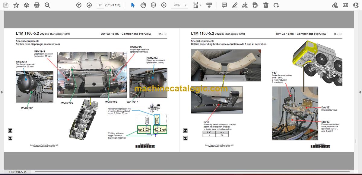
Switch over diaphragm reservoir rear………………………………………………….97
Ballast depending brake force reduction axle 1 and 2, activation…………….98
Ballast depending brake force reduction axle 3 – 5………………………………..99
Eddy currant brake Telma Focal 2200………………………………………………..100
Air-conditioner………………………………………………………………………………..101
Additional heating Thermo PRO 90……………………………………………………102
Additional heating Air Top 2000 ST……………………………………………………103
External power supply……………………………………………………………………..104
Back-up camera……………………………………………………………………………..105
Trailer coupling……………………………………………………………………………….106
Battery charger……………………………………………………………………………….107
Hydraulic emergency control…………………………………………………………….108
►► Index………………………………………………………………………………………….109
►►Crane cabin:…………………………………………………………………………………….. 3
▪▪Control stand …………………………………………………………………………………3
LICCON-monitor, pedals……………………………………………………………………3
Active joystick (AMS1), keyboard unit (LSB TE1) right………………………….. 4
Active joystick (AMS2), keyboard unit (LSB TE2) left…………………………….5
BKE (operation and control unit)………………………………………………………… 6
▪▪Cab installation……………………………………………………………………………….8
Wiper motor, washer pump………………………………………………………………..9
Heating – activation, temperature sensors………………………………………….. 10
►►Crane electric:………………………………………………………………………………..15
Battery box…………………………………………………………………………………….15
►►Switch cabinet:……………………………………………………………………………….16
Fuses, power supply boards LSB, voltage converter……………………………16
Relays, resistor modules………………………………………………………………….17
Universal in- / output module UEA, data logger 2, remote diagnosis……… 18
Diagnosis plug………………………………………………………………………………..19
Plug plate slewing platform………………………………………………………………20
Plug plate cab…………………………………………………………………………………21
Emergency operation – XNOT-plug…………………………………………………… 22
EMERGENCY OPERATION – resistors…………………………………………….. 23
►►Central greasing device:………………………………………………………………….24
Electric pump, grease cycle monitoring……………………………………………… 24
►►Overview drive assembly:……………………………………………………………….25
Installation view………………………………………………………………………………25
►►Diesel engine D944 A7 – 04 / D944 A7 – 03 Power Band H (Derivate):… 26
Engine control unit…………………………………………………………………………..26
Overview injection side…………………………………………………………………….27
Fuel pumps…………………………………………………………………………………….28
Fuel low pressure sensors……………………………………………………………….29
Liebherr Daisy-Chain diesel injection system………………………………………30
Injectors LCR-I S2…………………………………………………………………………..31
Type plates…………………………………………………………………………………….31
Overview exhaust side…………………………………………………………………….32
Charge air sensors and -preheating………………………………………………….. 33
Exhaust gas flap……………………………………………………………………………..34
Exhaust gas turbo charger with wastegate………………………………………… 35
Overview flywheel side and generator………………………………………………. 36
Speed sensors……………………………………………………………………………….37
Overview fan side……………………………………………………………………………38
Coolant, temperature sensor coolant………………………………………………… 39
Oil circuit………………………………………………………………………………………..40
Terminal resistor CAN-LIDEC (ECU-CAN2)………………………………………..41
Terminal resistor engine-CAN (ECU-CAN2)………………………………………..42
▪▪Only Power Band H H-engines……………………………………………………….43
External exhaust gas return eAGR……………………………………………………. 43
Intercooler temperature sensor…………………………………………………………44
Copyright by
Liebherr
LTM 1100-5.2 092947 (KD-series 1009) OW-02 • BMK – Component overview 2 of 96
Customer Service-Technical Documentation LWE
Originator: lweeng1; lweegm0 / Issue: 8/15/2018
* Customer‘s spec.
Note:
All stated pressures according to state of January 2018!
►►Exhaust gas after treatment SCR:……………………………………………………45
Overview exhaust gas system…………………………………………………………..45
Urea tank and tank sensor……………………………………………………………….46
Pump module and AdBlue-lines………………………………………………………..47
AdBlue-injector and upstream-sensors/downstream-sensors……………….. 48
Control units NOx-sensors/NH3-sensor…………………………………………….. 49
Ambient air and exhaust gas flap……………………………………………………… 50
►►Air filter system:……………………………………………………………………………..51
Air filter vacuum, air flap in suction air*……………………………………………… 51
►►Fuel system:………………………………………………………………………………….. 52
Fuel tank and tank sensor………………………………………………………………..52
Fuel delivery, fuel prefilter unit…………………………………………………………..53
►►Cooling system:……………………………………………………………………………..54
Cooler – fan drive…………………………………………………………………………….54
Coolant level sensor………………………………………………………………………..55
►►Pneumatic system:………………………………………………………………………….56
Air pressure compressor, cooler air-air……………………………………………… 56
►►Crane hydraulic:……………………………………………………………………………..57
Overview hydraulic components……………………………………………………….57
Overview hydraulic pumps……………………………………………………………….58
Oil cooler and temperature sensor hydraulic oil ………………………………….59
Pressure sensors, overview metering connection plate……………………….. 60
Main control block (LS)…………………………………………………………………….61
Pressure stages / telescoping…………………………………………………………..62
Hoist gear 1……………………………………………………………………………………63
Hoist gear 2*…………………………………………………………………………………..64
Luffing, activation lowering brake………………………………………………………65
Luffing……………………………………………………………………………………………66
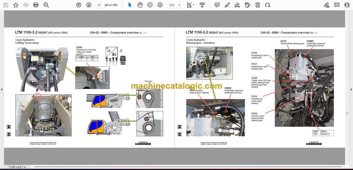
Luffing, boom steep…………………………………………………………………………67
Slewing gear – activation………………………………………………………………….68
Slewing gear – slewing angle display………………………………………………… 69
Boom direction……………………………………………………………………………….70
Auxiliary consumer valves………………………………………………………………..71
Locking slewing platform………………………………………………………………….72
Ballasting right………………………………………………………………………………..73
Ballasting left………………………………………………………………………………….74
Ballasting……………………………………………………………………………………….75
Telescoping cylinder – pretension……………………………………………………… 76
tilting cab……………………………………………………………………………………….77
►►Telescoping boom:………………………………………………………………………….77
▪▪Electric…………………………………………………………………………………………77
Cable drums and length sensors……………………………………………………….77
Cable drums and length sensors……………………………………………………….78
Boom head, boom nose…………………………………………………………………..79
▪▪Telematic………………………………………………………………………………………80
Position sensor……………………………………………………………………………….80
Tele section pinning…………………………………………………………………………81
Gripper pinning, position sensor………………………………………………………..82
Pressure supply unpinning……………………………………………………………….83
Emergency operation tele , gripper pinning…………………………………………84
►►Additional equipment double swing-away jib*:…………………………………85
Activation luffing at hydraulic double swing-away jib…………………………….85
Hydraulic components of the transport device…………………………………….86
Hydraulic components, angle sensor………………………………………………… 87
Hoist limit switch at single and double swing-away jib………………………….88
►►Special equipment*:………………………………………………………………………..89
Additional heating Thermo Pro 90*…………………………………………………… 89
Air condition*………………………………………………………………………………….90
Removable boom and luffing cylinder*………………………………………………. 91
Emergency control crane hydraulic*………………………………………………….. 92
Dolly operation* (dolly for boom transport USA)………………………………….93
►► Index……………………………………………………………………………………………… 94


