Format: PDF (Printable Document)
File Language: English
File Pages: 210
File Size: 54.33 MB (Speed Download Link)
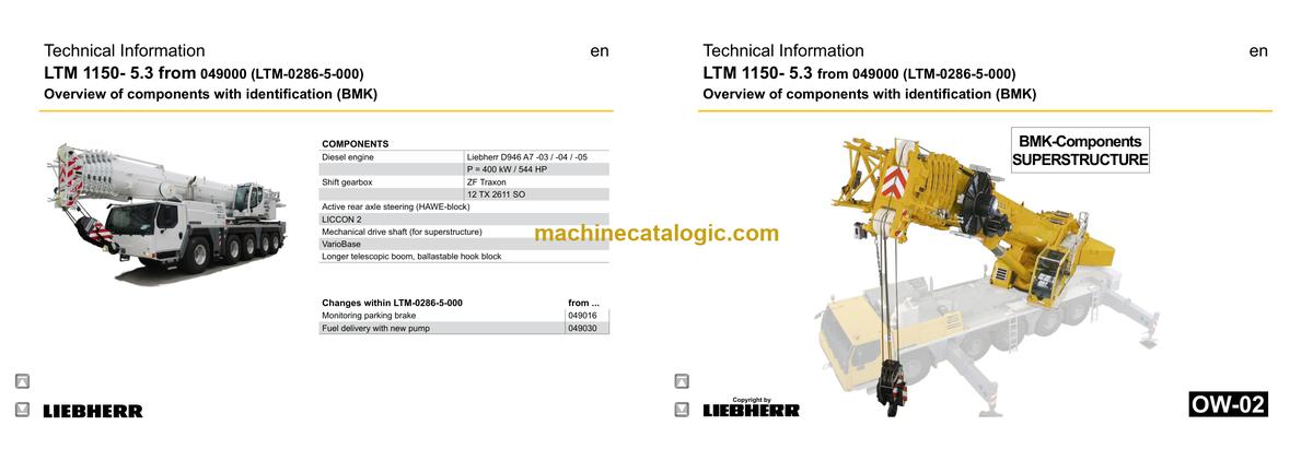
Brand: Liebherr
Model: LTM 1150-5.3 Mobile Crane
Components: Carrier + Superstructure
Serial No: SN 049146
Date: 2023
Type of Document: Technical Information & BMK Components Manual
$ 80
The Liebherr LTM 1150-5.3 Mobile Crane works hard on road and site, so when it throws a fault or a circuit isn’t behaving, techs need to know exactly where each component lives. That’s when a workshop technician or electrical diagnostic engineer reaches for the BMK / component identification manual, not the service book. Component identification matters because you can’t fix, test, or replace what you can’t physically find on the crane. Most new techs I train lose time simply hunting for “K15” or “V12” on the machine instead of actually diagnosing the problem.
What this manual helps you do
Who this is for
This Technical Information & BMK Components Manual is aimed at workshop technicians, field service techs, fleet mechanics, and trainers who already have (or plan to use) service manuals and schematics. If you need repair steps, test procedures, or part numbers, you want the service manual and parts catalogue instead of this BMK alone.
FAQ
Q: Are the diagrams clear and searchable in the PDF?
A: Yes, this kind of BMK PDF is meant to be zoomed and searched so you can read designators and find component IDs quickly.
Q: Does it cover both the carrier and the superstructure?
A: Yes, it combines BMK information for the lower carrier and the upper crane superstructure in one product.
Q: Does it work with other Liebherr documentation?
A: Yes, the BMK reference designators are designed to match Liebherr wiring diagrams, hydraulic schematics, service manuals, and parts catalogues.
Bottom line: If your main need is to find and identify components on the Liebherr LTM 1150-5.3 by their BMK codes, this is the right manual. If you’re hoping for repair instructions or parts lists, this is not what you need.
► Chassis:…………………………………………………………………………………. 5
View from front, lighting and mirror……………………………………………… 5
View rear, lighting……………………………………………………………………… 6
Vehicle lighting right………………………………………………………………….. 7
Vehicle lighting left……………………………………………………………………. 8
Trailer coupling*, warning signal…………………………………………………. 9
Control elements…………………………………………………………………….. 10
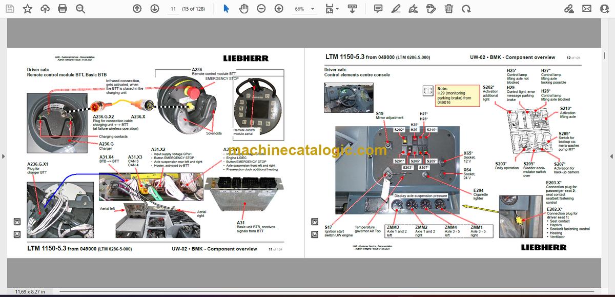
Remote control module BTT, Basic BTB……………………………………..11
Control elements centre console………………………………………………. 12
► Driver cab:……………………………………………………………………………. 13
Doors and windows, interior lighting………………………………………….. 13
Screen wiper and – washer………………………………………………………. 14
Heating – ventilation and heat exchanger…………………………………… 15
Air-conditioner………………………………………………………………………… 16
Wiring loom – backup camera, radio………………………………………….. 17
Centre console – battery, main switch, fuse box………………………….. 18
Center console – I/O modules, BTB…………………………………………… 19
Centre console – fuses…………………………………………………………….. 20
Centre console – relay……………………………………………………………… 21
Centre console – relays (from 049016)………………………………………. 22
Centre console – relay……………………………………………………………… 23
Centre console – voltage converter, activation heating flange……….. 24
Centre console – control unit ABV, components…………………………… 25
Centre console – fan, component carrier, EMERGENCY STOP…….. 26
Centre console – diagnosis plug……………………………………………….. 27
Telemetry FMS-interface………………………………………………………….. 28
► Pneumatic system:……………………………………………………………….. 29
Air compressor and air dryer……………………………………………………. 29
Pressure reservoir………………………………………………………………….. 30
Pneumatic valves in the driver cab……………………………………………. 31
Brake relay- and overload protection valve………………………………… 32
Filter and overflow valve, measuring points compressed air circuits.33
Solenoid valve for auxiliary users……………………………………………… 34
Pressure sensors and pressure switches…………………………………… 35
Monitoring parking brake (from 049016)…………………………………….. 36
Disk brake system:……………………………………………………………….. 37
Overview – brake system…………………………………………………………. 37
Overview – brake pad monitoring………………………………………………. 38
Brake pad monitoring indicator…………………………………………………. 39
ABV – regulating valves…………………………………………………………… 40
ABV – wheel speed sensors……………………………………………………… 41
Hill start assist………………………………………………………………………… 42
► Drive assembly:……………………………………………………………………. 43
Installation view……………………………………………………………………… 43
Diesel engine – installation……………………………………………………….. 44
Diesel engine D946 A7 -03 (eAGR) 04 (SCR) / -05 (SCRF):………. 45
Engine control unit………………………………………………………………….. 45
LWE – Customer Service – Documentation
Author: lweegm0 / Issue: 31.08.2021
LTM 1150-5.3 from 049000 (LTM 0286-5-000) UW-02 • BMK – Component overview 2 of 124
Overview injection side……………………………………………………………. 46
Fuel pumps……………………………………………………………………………. 47
Fuel low pressure sensors……………………………………………………….. 48
Liebherr Daisy-Chain diesel injection system……………………………… 49
Injectors LCR-I S2………………………………………………………………….. 50
Type plates:…………………………………………………………………………… 50
Overview exhaust side…………………………………………………………….. 51
Charge air sensors and -preheating………………………………………….. 52
Exhaust gas flap…………………………………………………………………….. 53
Exhaust gas turbo charger with wastegate…………………………………. 54
Overview flywheel side and generator……………………………………….. 55
Speed sensors……………………………………………………………………….. 56
Overview fan side…………………………………………………………………… 57
Coolant, temperature sensor coolant and ambient temperature……. 58
Oil circuit……………………………………………………………………………….. 59
Terminal resistor CAN-LIDEC (ECU-CAN2)……………………………….. 60
Terminal resistor engine-CAN (ECU-CAN2)……………………………….. 61
External exhaust gas return eAGR……………………………………………. 62
Intercooler temperature sensor…………………………………………………. 63
► Exhaust gas system……………………………………………………………… 64
Exhaust after treatment SCRonly:…………………………………………. 64
Overview……………………………………………………………………………….. 64
AdBlue-injector and upstream-sensors………………………………………. 65
Downstream sensors………………………………………………………………. 66
Exhaust after treatment SCRF:………………………………………………. 67
Overview……………………………………………………………………………….. 67
AdBlue-injector and upstream-sensors………………………………………. 68
Downstream sensors………………………………………………………………. 69
Exhaust after treatment SCRonly / SCRF:………………………………. 70
Urea tank and tank sensor……………………………………………………….. 70
Pump module and AdBlue-lines………………………………………………… 71
► Air filter system:…………………………………………………………………… 72
Air filter-vacuum, air flap………………………………………………………….. 72
► Diesel fuel system:……………………………………………………………….. 73
Prefilter unit and tank………………………………………………………………. 73
► Diesel fuel system:……………………………………………………………….. 74
Prefilter unit (from 049030)………………………………………………………. 74
► Cooling system:……………………………………………………………………. 75
Cooler – fan drive, level sensor…………………………………………………. 75
► Automated shift gearbox:……………………………………………………… 76
ZF-Traxon 12 TX 2611 SO (intarder 3)………………………………………. 76
Intarder 3, clutch actuation unit (ConAct)…………………………………… 77
► Hydraulic:…………………………………………………………………………….. 78
Temperature sensor hydraulic oil, hydraulic oil tank…………………….. 78
Hydraulic pumps – overview……………………………………………………… 79
Fan valve, pretension centering pressure…………………………………… 80
► Drive train:……………………………………………………………………………. 81
Overview……………………………………………………………………………….. 81
Distribution gearbox Kessler VG 2700 (two stage)………………………. 82
Road-/ offroad gear – switching…………………………………………………. 83
Travel drive / crane drive (PTO) – switching………………………………… 84
Crane drive……………………………………………………………………………. 85
Transversal differential lock axle 1…………………………………………….. 86
Longitudinal differential lock distribution gear……………………………… 86
Transversal differential lock axle 2, activation axle 1*………………….. 87
Long. and transv. differential lock axle 4 and 5……………………………. 88
► Steering:………………………………………………………………………………. 89
Steering from superstructure……………………………………………………. 89
Steering gear ZF-SERVOCOM………………………………………………… 90
Oil supply steering circuit 1, deficiency monitoring………………………. 91
Oil supply steering circuit 2………………………………………………………. 92
Active rear axle steering:………………………………………………………. 93
CAN-Valves (HAWE) ……………………………………………………………… 93
Control block………………………………………………………………………….. 94
Valve block ……………………………………………………………………………. 95
Oil filter………………………………………………………………………………….. 96
Angle sensor………………………………………………………………………….. 97
Steering- and centering cylinder, safety valves…………………………… 98
► Support:……………………………………………………………………………….. 99
Inclination sensor……………………………………………………………………. 99
Support valves – right…………………………………………………………….. 100
Support valves – left………………………………………………………………. 101
Extension cylinder…………………………………………………………………. 102
Sliding beam monitoring………………………………………………………… 103
Support cylinder……………………………………………………………………. 104
Monitoring support pressure…………………………………………………… 105
► Axle suspension:………………………………………………………………… 106
Level sensor- axle suspension……………………………………………….. 106
Valve block – axle suspension right………………………………………….. 107
Valve block – axle suspension left……………………………………………. 108
Switch over diaphragm reservoir*……………………………………………. 109
► Special equipment:……………………………………………………………….110
Brake force redustion axle 1 and 2……………………………………………110
Brake force reduction axle 3 – 5……………………………………………….. 111
Eddy currant brake Telma Focal 2200*………………………………………112
Additional heating – Thermo Pro 90…………………………………………..113
Additional heating – Air Top 2000 ST*………………………………………..114
Additional heating – engine pre-heating*…………………………………….115
External power supply…………………………………………………………….116
Back-up camera*……………………………………………………………………117
Battery charger………………………………………………………………………118
Hydraulic emergency control……………………………………………………119
► Index………………………………………………………………………………….. 120
► Haftungsbegrenzung / Disclaimer………………………………………… 124
► Crane cabin:…………………………………………………………………………………….. 3
▪ Control stand …………………………………………………………………………………3
LICCON-monitor, pedals……………………………………………………………………3
Active joystick (AMS1), keyboard unit (LSB TE1) right………………………….. 4
Active joystick (AMS2), keyboard unit (LSB TE2) left…………………………….5
BKE (operation and control unit)………………………………………………………… 6
▪ Cab installation……………………………………………………………………………….8
Wiper motor, washer pump………………………………………………………………..9
Heating – temperature sensors………………………………………………………….10
Heating Thermo Pro 90……………………………………………………………………12
▪ Crane electric:………………………………………………………………………………15
Flood light………………………………………………………………………………………15
Sensor…………………………………………………………………………………………..16
► Switch cabinet:……………………………………………………………………………….17
Fuses, power supply boards LSB, voltage converter……………………………17
Relays, resistor modules………………………………………………………………….18
Universal in- / output module UEA, data logger 2, remote diagnosis……… 19
Diagnosis plug………………………………………………………………………………..20
Plug plate slewing platform………………………………………………………………21
Plug plate cab…………………………………………………………………………………22
Emergency operation – XNOT-plug…………………………………………………… 23
EMERGENCY OPERATION – resistors…………………………………………….. 24
► Central greasing device:………………………………………………………………….25
Electric pump, grease cycle monitoring……………………………………………… 25
► Crane drive:…………………………………………………………………………………… 26
▪ Mechanical shaft…………………………………………………………………………..26
▪ Angle gear box……………………………………………………………………………..27
▪ Distribution gearbox……………………………………………………………………..28
► Crane hydraulic:……………………………………………………………………………..29
Overview hydraulic components right……………………………………………….. 29
Overview hydraulic components left………………………………………………….. 30
Overview hydraulic pumps, temperature switch hydraulic oil………………… 31
Oil cooler, pressure supply tele pinning……………………………………………… 32
Main control block (LS)…………………………………………………………………….33
Pressure stages / telescoping…………………………………………………………..34
Actuation slewing gear brake, luffing…………………………………………………. 35
Oil filter………………………………………………………………………………………….36
Overview metering connector plate…………………………………………………… 37
Slewing gear – activation………………………………………………………………….38
Slewing gear…………………………………………………………………………………..40
Boom direction……………………………………………………………………………….41
Auxiliary consumer valves………………………………………………………………..42
Locking slewing platform………………………………………………………………….43
Hoist gear 1 and 2 winch speed sensor / connections hoist gear 2……….. 44
Hoist gear I…………………………………………………………………………………….45
Hoist gear 2*…………………………………………………………………………………..46
Luffing, boom steep…………………………………………………………………………47
Copyright by
liebherr
LTM 1150-5.3 from 049000 (LTM-0286-5-000) OW-02 • BMK – Component overview 2 of 80
LWE – customer service – documentation
Originator: lweeng1 / Edition: 03.05.2020
* Customer‘s spec.
Note:
All stated pressures according to state of September 2020!
Ballasting right………………………………………………………………………………..48
Ballasting left………………………………………………………………………………….49
Ballasting……………………………………………………………………………………….50
Ballast recognition…………………………………………………………………………..51
Telescoping cylinder – pretension……………………………………………………… 52
Tilting cab………………………………………………………………………………………53
► Telescoping boom:………………………………………………………………………….54
▪ Electric…………………………………………………………………………………………54
Cable drums and length sensors……………………………………………………….54
Length sensor…………………………………………………………………………………55
Cable drums and length sensors……………………………………………………….56
Boom head…………………………………………………………………………………….57
Boom head, boom nose…………………………………………………………………..58
▪ Telematic………………………………………………………………………………………59
Position sensor……………………………………………………………………………….59
Tele section pinning…………………………………………………………………………60
Gripper pinning, position sensor………………………………………………………..61
Emergency operation tele , gripper pinning…………………………………………62
► Additional equipment double swing away jib*:………………………………… 64
Activation luffing at hydraulic double swing away jib…………………………….64
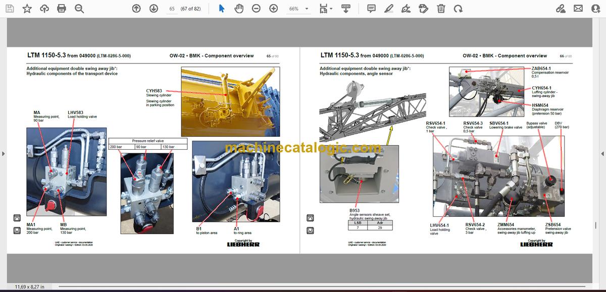
Hydraulic components of the transport device…………………………………….65
Hydraulic components, angle sensor………………………………………………… 66
Hoist limit switch at single and double swing-away jib………………………….67
Angle sensor………………………………………………………………………………….68
Special swing away jib THK*:……………………………………………………………69
Aircraft warning light, wind sensor…………………………………………………….. 69
► Special equipment*:………………………………………………………………………..70
Removable boom*…………………………………………………………………………..70
Emergency control crane hydraulic*………………………………………………….. 71
Air condition*………………………………………………………………………………….73
Dolly operation* (trailer for boom transport USA)…………………………………74
Camera monitoring*………………………………………………………………………..75
Oil preheating*………………………………………………………………………………..76
Foot pedal*…………………………………………………………………………………….77
► Index……………………………………………………………………………………………… 78


