Format: PDF (Printable Document)
File Language: English
File Pages: 168
File Size: 46.82 MB (Speed Download Link)
Brand: Liebherr
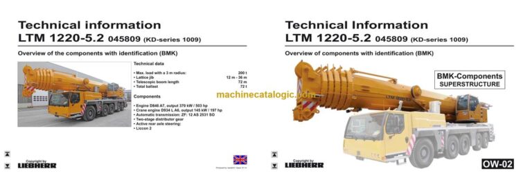
Model: LTM 1220-5.2 Mobile Crane
Components: Carrier + Superstructure
Serial No: SN 045798
Date: 2023
Type of Document: Technical Information & BMK Components Manual
$ 80
The Liebherr LTM 1220-5.2 Mobile Crane earns its keep on lifts where reach, roadability, and setup time matter, so knowing exactly where each component sits is half the battle. The Technical Information & BMK Components Manual for SN 045798 is what techs grab when a schematic says “K15” or “V23” and they need to find that part on the actual crane. This kind of component identification manual saves real time in the workshop and out in the yard because you’re not guessing behind panels and boom sections. It’s not a fix-it book; it’s the map that lets you get to the right spot fast.
What this manual helps you do
Who this is for
This suits a workshop technician, field service tech, electrical diagnostic engineer, fleet mechanic, or training instructor who already has or plans to use wiring diagrams and service data. If you’re after repair procedures, torque specs, or part numbers, you need a service manual or parts catalogue instead, not this BMK.
FAQ
Q: Are the diagrams clear and searchable?
A: It’s provided as a readable PDF, so you can zoom and text-search BMK codes and terms.
Q: Does it cover both carrier and superstructure?
A: Yes, it combines BMK component identification for the lower carrier and the upper crane body in one product.
Q: Does it tie in with other Liebherr documents?
A: Yes, the BMK references are meant to be used alongside Liebherr wiring diagrams, hydraulic schematics, and parts catalogues.
Bottom line: If you need to find and identify components on an LTM 1220-5.2 by BMK code or location, this is exactly the right manual; if you want how-to-repair instructions, it’s the wrong one.
►►Vehicle:………………………………………………………………………………………….3
View from front, lighting and mirrors……………………………………………………… 3
View from rear, lighting……………………………………………………………………….. 4
Vehicle lighting, right side……………………………………………………………………. 5
Vehicle lighting, left side……………………………………………………………………… 6
Sockets, warning signal generators……………………………………………………… 7
►►Cab:………………………………………………………………………………………………8
Doors and windows, interior lighting…………………………………………………….. 8
Ventilation and heat exchangers …………………………………………………………. 9
Controls………………………………………………………………………………………….. 10
BTB Bluetooth base unit…………………………………………………………………… 11
BTT Bluetooth terminal……………………………………………………………………… 11
Center console controls……………………………………………………………………. 12
Batteries and main fuse box………………………………………………………………. 13
Center console – terminal block, ground distribution……………………………… 14
Center console – I/O modules, BTB……………………………………………………. 15
Center console – fuses……………………………………………………………………… 16
Center console – relays…………………………………………………………………….. 17
Center console – emergency operation and diagnostic connector…………… 18
Center console – control unit, interval relays………………………………………… 19
Center console – voltage transformer, fan……………………………………………. 20
►►Compressed air system:………………………………………………………………21
Air compressor and dryer………………………………………………………………….. 21
Compressed air reservoir………………………………………………………………….. 22
Pressure sensors and switches in the brake system…………………………….. 23
Valve block, auxiliary users……………………………………………………………….. 24
Disk brake system brake pad monitor…………………………………………………. 25
Brake pad monitoring indicator………………………………………………………….. 26
►►Diesel engine D 846 A7, 370 kW/503 HP (Common Rail):………………..27
Overview drive assembly………………………………………………………………….. 27
Engine view left……………………………………………………………………………….. 28
Engine view right……………………………………………………………………………… 29
Engine view flywheel side…………………………………………………………………. 30
Engine view top……………………………………………………………………………….. 31
Injectors………………………………………………………………………………………….. 32
Fuel pumps…………………………………………………………………………………….. 33
Fuel-Service-Centre KSC………………………………………………………………….. 34
Rail pressure centre…………………………………………………………………………. 35
Pressure relief valve in fuel system…………………………………………………….. 36
Hollow srews for pressure limitation in the fuel system………………………….. 37
Speed sensor………………………………………………………………………………….. 38
Charge air sensor…………………………………………………………………………….. 39
Oil pressure sensor………………………………………………………………………….. 40
Water cooled external exhaust gas return……………………………………………. 41
Flame start device……………………………………………………………………………. 42
Engine control unit, air filter pressure………………………………………………….. 43
Coolant level and temperature…………………………………………………………… 44
►►Diesel fuel system:……………………………………………………………………….45
Fuel preliminary filter………………………………………………………………………… 45
Fuel tank………………………………………………………………………………………… 46
Copyright by
Liebherr
LTM 1220-5.2 045809 (KD-series 1009) UW-02 • BMK – Component overview 2 of 82
Kundendienst-Technische Dokumentation LWE
Produced by: lwedoh3 / Issue: 17.01.2014
* Optional
►►Cooling system:…………………………………………………………………………..47
►►Automatic transmission ZF 12 AS 2531 SO with Intarder:………………48
Clutch and transmission actuators……………………………………………………… 48
Intarder…………………………………………………………………………………………… 49
►►Hydraulics:…………………………………………………………………………………..50
Hydraulic pumps – overview………………………………………………………………. 50
Hydraulic oil temperature sensor, hydraulic oil tank………………………………. 51
►►Power train:…………………………………………………………………………………52
Overview………………………………………………………………………………………… 52
Distribution gearbox- Kessler VG 3750 (2-stage)…………………………………. 53
Distribution gearbox toggling road/offroad gear…………………………………… 54
Differential lock, axle 1 and 2…………………………………………………………….. 55
Differential lock, axle 4 and 5…………………………………………………………….. 56
►►Steering:………………………………………………………………………………………57
Steering gear…………………………………………………………………………………… 57
Fault monitoring………………………………………………………………………………. 58
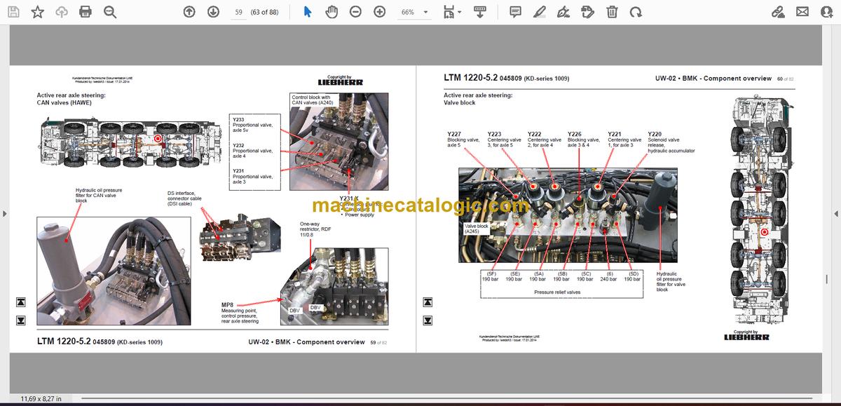
►►Active rear axle steering:……………………………………………………………..59
CAN valves (HAWE)………………………………………………………………………… 59
Valve block……………………………………………………………………………………… 60
Pressure switch, flow switch, measurement points……………………………….. 61
Steering and centering cylinders………………………………………………………… 62
Angle sensors…………………………………………………………………………………. 63
►►Support:………………………………………………………………………………………64
Incline sensor………………………………………………………………………………….. 64
Supporting valves – right…………………………………………………………………… 65
Supporting valves – left……………………………………………………………………… 66
►►Axle suspension:…………………………………………………………………………67
Axle suspension / support oil supply…………………………………………………… 67
Compressed air valves for the axle spring suspension………………………….. 68
Filling and draining valves, left…………………………………………………………… 69
Filling and draining valves, right…………………………………………………………. 70
Axle suspension level sensor…………………………………………………………….. 71
►►Special equipment:………………………………………………………………………72
Eddy current brake FN72-20 retarder (FOCAL 2200)*…………………………… 72
External power supply*, back-up camera* ………………………………………….. 73
Auxiliary heater Thermo 90 ST *………………………………………………………… 74
Additional heating Airtop 2000ST*……………………………………………………… 75
Engine preheating Airtop EVO 5500 D / DBW 2020*…………………………….. 76
Air conditioning system*……………………………………………………………………. 77
Sliding beam* / support pressure monitoring*………………………………………. 78
Battery charging devíce*…………………………………………………………………… 79
Change over brake system*………………………………………………………………. 80
►► Index……………………………………………………………………………………………81
►►Superstructure general:…………………………………………………………………3
Illumination slewing platform……………………………………………………………….. 3
Illumination boom………………………………………………………………………………. 4
LMB warning device (EN 13000)…………………………………………………………. 5
Central greasing device …………………………………………………………………….. 6
►►Crane electric:……………………………………………………………………………….7
Battery box……………………………………………………………………………………….. 7
►►Crane cab:……………………………………………………………………………………..8
Heating…………………………………………………………………………………………….. 8
Heating – activation, temperature sensors…………………………………………….. 9
Wiper motors, washer pump……………………………………………………………… 10
Interior fittings………………………………………………………………………………….. 11
Platform cab……………………………………………………………………………………. 12
►► Instruments cab:………………………………………………………………………….13
Liccon monitor, pedals……………………………………………………………………… 13
Joystick1, LSB-TE1 right…………………………………………………………………… 14
Joystick 2, LSB-TE2 left……………………………………………………………………. 15
Operation and control unit…………………………………………………………………. 16
►►Switch cabinet crane cab:…………………………………………………………….17
Tilting frame – fuses………………………………………………………………………….. 17
Universal input/output module UEA / BTB2 / BTB3………………………………. 18
Tilting frame – plug plate slewing platform……………………………………………. 19
Tilting frame – plug plate slewing cab………………………………………………….. 20
Mounting plate – LSB-master, diode module………………………………………… 21
Mounting plate – relays……………………………………………………………………… 22
Mounting plate – power supply, resistor module……………………………………. 23
Air circulation cab cabinet, voltage converter……………………………………….. 24
Data logger II, remote diagnosis………………………………………………………… 25
Diagnosis plug, earth divider……………………………………………………………… 26
Emerg. operation – sockets……………………………………………………………….. 27
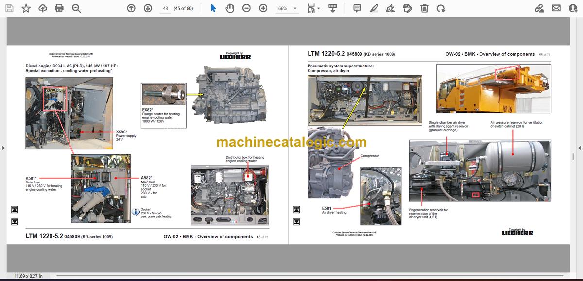
►►Diesel engine D934 L A6 (PLD), 145 kW / 197 HP:…………………………..28
Installation view ………………………………………………………………………………. 28
Engine view right……………………………………………………………………………… 29
►►Diesel engine D934 L A6 (PLD), 145 kW / 197 HP:…………………………..30
Oil pressure sensor and fuel temperature sensor…………………………………. 31
Fuel prefilter unit……………………………………………………………………………… 32
Engine view left……………………………………………………………………………….. 33
Engine view top……………………………………………………………………………….. 34
Engine view front……………………………………………………………………………… 35
RPM sensor……………………………………………………………………………………. 36
Inlet air, engine brake*……………………………………………………………………… 37
Cooler – ventilator drive…………………………………………………………………….. 38
Charge air pressure and temperature sensor………………………………………. 39
Fuel tank and tank sensor…………………………………………………………………. 40
Coolant level sensor and coolant temperature sensor…………………………… 41
Engine control unit, diagnosis……………………………………………………………. 42
Special execution – cooling water preheating*……………………………………… 43
Copyright by
Liebherr
LTM 1220-5.2 045809 (KD-series 1009) OW-02 • BMK – Overview of components 2 of 76
Customer Service-Technical Documentation LWE
Produced by: lwedoh3 / Issue: 12.02.2014
*Customer spec.
Note
All stated pressures relate to the level
of January 2014!
►►Pneumatic system superstructure:……………………………………………….44
Compressor, air dryer……………………………………………………………………….. 44
►►Crane hydraulic:…………………………………………………………………………..45
Overview hdraulic pumps………………………………………………………………….. 45
Pumps 1, 2, 12………………………………………………………………………………… 46
Pumps 7, 8, 11, 14…………………………………………………………………………… 47
Overview hydraulic components………………………………………………………… 48
Slewing gear – activation, brake…………………………………………………………. 49
Slewing gear – boom direction……………………………………………………………. 50
Hoist gear 1…………………………………………………………………………………….. 51
Hoist gear 2*…………………………………………………………………………………… 52
Luffing, telescoping………………………………………………………………………….. 53
Luffing, telescoping………………………………………………………………………….. 54
Auxiliary consumers, locking slewing platform……………………………………… 55
Auxiliary consumers – metering points………………………………………………… 56
Pressure stage supporting consumers………………………………………………… 57
Ballasting………………………………………………………………………………………… 58
Temperature sensor and oil cooler……………………………………………………… 59
►►Telescopic boom:…………………………………………………………………………60
Heel section, „boom steep“……………………………………………………………….. 60
Boom head……………………………………………………………………………………… 61
Extension mechanics (Telematik) – tele pinning……………………………………. 62
Extension mechanics (Telematik) – cylinder pinning……………………………… 63
Emerg. operation tele- / cylinder pinning……………………………………………… 64
►►Special equipment:………………………………………………………………………65
Swing-away jib* / special auxiliary jib* – electric……………………………………. 65
Swing-away jib* – hydraulic……………………………………………………………….. 66
Additional heating Thermo 90ST*………………………………………………………. 67
Engine preheating DBW 2020*………………………………………………………….. 68
Air condition*…………………………………………………………………………………… 69
Emerg. operation crane hydraulic*……………………………………………………… 70
Dolly* (trailer for boom transport)……………………………………………………….. 71
Tele dismounting*…………………………………………………………………………….. 72
Camera winch*………………………………………………………………………………… 73
►► Index:…………………………………………………………………………………………..74


