Format: PDF (Printable Document)
File Language: English
File Pages: 291
File Size: 61.64 MB (Speed Download Link)
Brand: Liebherr
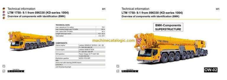
Model: LTM 1750-9.1 Mobile Crane
Components: Carrier + Superstructure
Serial No: SN 096339
Date: 2023
Type of Document: Technical Information & BMK Components Manual
$ 80
The Liebherr LTM 1750-9.1 Mobile Crane is a big all‑terrain lifter that earns its keep on wind jobs, heavy industrial picks, and long‑radius work. When something’s acting up, the first person grabbing a BMK on my shop floor is the tech trying to match a fault or schematic tag to a real box, valve, or sensor on the machine. Component identification is what keeps you from wasting half a day hunting for “K-something” or “that solenoid on the third outrigger.” The Technical Information & BMK Components Manual for SN 096339 is built exactly for that job, not for turning wrenches step‑by‑step.
What this manual helps you do
Who this is for
This is for workshop technicians, field service techs, electrical diagnostic engineers, fleet mechanics, and training instructors who need layout and identification, not instructions. If you’re after repair procedures, torque specs, pressures, or part numbers, you want the service manual and the parts catalogue instead.
FAQ
Q: Are the diagrams clear and searchable in the PDF?
A: Yes, this kind of BMK PDF is normally zoomable and readable, with layout drawings you can follow on a laptop or tablet in the bay.
Q: Does it cover both the carrier and the upper crane body?
A: Yes, this BMK combines carrier and superstructure component identification for the LTM 1750-9.1 into one product.
Q: Does it tie in with other Liebherr manuals?
A: Yes, the BMK component IDs are meant to line up with wiring diagrams, hydraulic schematics, and parts catalogues for the same crane.
Bottom line: If your main need is to find and name components on a Liebherr LTM 1750-9.1 for SN 096339, this BMK / component identification manual is exactly what you want. If you’re hoping for repair steps or part numbers, it’s the wrong book.
► Chassis:……………………………………………………………………………….5
View from front, lighting and mirror……………………………………………5
View from rear, lighting……………………………………………………………6
Illuminations left and right side…………………………………………………7
► Driver cab…………………………………………………………………………….8
Doors and windows, interior lighting………………………………………….8
Screen wiper and washer, ventilation valves………………………………9
Ventilation and heat exchanger………………………………………………10
Control elements………………………………………………………………….. 11
Basic unit – BTB,
remote control module – BTT………………………………………………….12
Control elements centre console…………………………………………….13
FMS-interface………………………………………………………………………14
Centre console – I/O- modules, BTB, ABV control unit……………….15
Centre console – battery box…………………………………………………..16
Centre console – fuses…………………………………………………………..17
Centre console – relay……………………………………………………………18
Centre console – voltage converter, heating flange……………………19
Centre console – components…………………………………………………20
Centre console – diagnosis plug……………………………………………..21
Air-conditioner………………………………………………………………………22
► Pneumatic system………………………………………………………………23
Pressure reservoir………………………………………………………………..23
Compressor (air compressor) and air dryer………………………………24
Solenoid valve for auxiliary users……………………………………………25
Pressure switch for axle suspension and brake system……………..26
Disk brake system, brake pad control………………………………………27
Disk brake system, brake cylinder…………………………………………..28
Brake relay- / overload protection valve…………………………………..29
Pneumatic valves in the driver cab………………………………………….30
Brake pad monitoring indicator……………………………………………….31
ABV – valve………………………………………………………………………….32
► D9508 A7 -03 (eAGR) / -04 (SCRonly) / -05 (SCRF)………………..33
Plug connection diesel engine………………………………………………..33
Overview V-area and preheating diesel engine filter………………….34
Engine control unit………………………………………………………………..35
Injectors LCR-I S2………………………………………………………………..36
Type plates………………………………………………………………………….36
Fuel low pressure sensors……………………………………………………..37
Fuel pumps………………………………………………………………………….38
Charge air preheating and sensors…………………………………………39
Exhaust gas turbo charger with wastegate……………………………….40
Coolant- temperature sensor………………………………………………….41
Overview fly-wheel side…………………………………………………………42
Speed-and camshaft sensor…………………………………………………..43
Starter and generator…………………………………………………………….44
Copyright by
liebherr
LWE – Customer Service – Documentation
Author: lwebef1 / Issue: 19.03.2020
LTM 1750- 9.1 from 096330 (KD-series 1004) UW-02 • BMK – Component overview 2 of 113
Overview fan side…………………………………………………………………45
LIEBHERR-oil module with oil pressure sensor………………………..46
Oil level and temperature sensor…………………………………………….47
Exhaust gas flap…………………………………………………………………..48
Diesel engine D9508 A7 -03 (eAGR) / Powerband H………………49
External exhaust gas return eAGR………………………………………….49
Intercooler temperature sensor……………………………………………….50
► Exhaust after treatment SCR……………………………………………….51
Urea tank and tank sensor……………………………………………………..51
Pump module and AdBlue-lines………………………………………………52
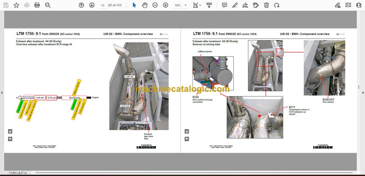
Exhaust after treatment -04 (SCRonly)…………………………………53
Overview exhaust after treatment SCR stage IV……………………….53
Sensors at mixing tube………………………………………………………….54
Sensors behind the catalysor…………………………………………………55
Exhaust after treatment -05 (SCRF)……………………………………..56
Overview exhaust after treatment SCRF stage V………………………56
AdBlue-injector and upstream-sensors…………………………………….57
Downstream-sensors, differential pressure………………………………58
► Diesel fuel system………………………………………………………………59
Prefilter unit and tank…………………………………………………………….59
► Air filter system…………………………………………………………………..60
Air filter vacuum……………………………………………………………………60
► Cooling system…………………………………………………………………..61
Overview……………………………………………………………………………..61
Cooling water level, return fan………………………………………………..62
► TRAXON TORQUE 12 TT 3021 SO:……………………………………….63
Overview of components……………………………………………………….63
Torque converter…………………………………………………………………..64
Shift gearbox Traxon:…………………………………………………………….65
Intarder……………………………………………………………………………….66
► Hydraulic supply…………………………………………………………………67
Overview hydraulic pumps……………………………………………………..67
Temperature sensor hydraulic oil, hydraulic oil tank…………………..68
Support and axle suspension…………………………………………………69
► Drive train…………………………………………………………………………..70
Overview, shifting conditions………………………………………………….70
Differential locks……………………………………………………………………71
ABV – wheel speed sensors……………………………………………………72
Distribution gearbox W3751 PTO SPF………………………………….73
Pumps, sensor, switch…………………………………………………………..73
Switch over travel drive / crane drive (PTO)……………………………..74
► Steering……………………………………………………………………………..75
Steering gear, steering circuit control………………………………………75
► Active rear axle steering……………………………………………………..76
Flow and pressure monitoring………………………………………………..76
Pretension centering cylinder…………………………………………………77
CAN valve axle 6-7, control block……………………………………………78
CAN valve axle 8-9, control block……………………………………………79
Steering- and centering cylinder, safety valves…………………………80
Angle sensor………………………………………………………………………..81
► Support………………………………………………………………………………82
Inclination sensor………………………………………………………………….82
Pinning folding outrigger top…………………………………………………..83
Valves for folding outrigger left………………………………………………..84
Valves for folding outrigger right……………………………………………..85
Connections folding outriggers left………………………………………….86
Connections folding outriggers right………………………………………..87
Support force monitoring with pressure sensor…………………………88
Support cylinder……………………………………………………………………90
Angle support beams…………………………………………………………….91
Axle suspension…………………………………………………………………93
Level sensor- axle suspension……………………………………………….93
Axle suspension blocked / sprung, axle compensation………………94
Axle locking valves left…………………………………………………………..95
Axle locking valves right………………………………………………………..96
Acknowledgement axle compensation…………………………………….97
Pretensioning the axles in supported mode………………………………98
► Special equipment…………………………………………………………….100
Additional heating……………………………………………………………….100
Eddy currant brake Telma FN 72 – 20 (Focal 2200)………………….101
Tele self erection – rear support connections…………………………..102
Tele self erection – rear support valves…………………………………..103
Tele self erection – lifting bracket connections………………………..104
Tele self assembly – lifting bracket valves………………………………105
Tele self assembly – boom support connections………………………106
Back-up camera………………………………………………………………….107
EMERGENCY STOP driver cab……………………………………………108
External power supply…………………………………………………………109
► Index………………………………………………………………………………..110
Inhalt
► Crane – overview…………………………………………………………………..5
► Operating modes – overview………………………………………………….6
► Crane cabin: Control stand……………………………………………………7
LICCON-monitor, pedals………………………………………………………….7
LSB-BUS controls overview……………………………………………………..8
Active joystick (AMS1),
keyboard unit (LSB TE1) right…………………………………………………..9
Crane cabin: Control stand…………………………………………………….10
Active joystick (AMS2),
keyboard unit (LSB TE2) left…………………………………………………..10
Crane cabin: Control stand……………………………………………………. 11
BKE (operation and control unit)…………………………………………….. 11
Control elements side console………………………………………………..12
Crane operator’s cab camera monitor……………………………………..13
Camera monitor winches; ballast…………………………………………….14
Camera monitoring TY-suspension………………………………………….15
Crane cabin: ………………………………………………………………………16
Lighting crane cabin and ballast……………………………………………..16
Lighting slewing platform……………………………………………………….17
Crane cabin: Cab installation………………………………………………18
Radio, interior illumination, driver seat……………………………………..18
Wiper motor, washer pump…………………………………………………….19
Heating – activation, temperature sensors………………………………..20
Heater – heating/air conditioning device…………………………………..21
Heating……………………………………………………………………………….22
Air condition*………………………………………………………………………..23
LMB warning device (EN 13000),
diesel engine emergency control alarm……………………………………25
Switch cabinet crane cabin:………………………………………………..26
Fuses and plug connections…………………………………………………..26
Plug…………………………………………………………………………………….27
Data logger 2, mobile radio-module…………………………………………28
Diagnosis plug……………………………………………………………………..29
Ethernet Switch…………………………………………………………………….30
Relays, resistor modules……………………………………………………….31
► Crane electric:…………………………………………………………………….32
Battery box…………………………………………………………………………32
Switch cabinet…………………………………………………………………….34
Fuses………………………………………………………………………………….34
Current sources, fan……………………………………………………………..35
Plug connections………………………………………………………………….36
Overview UEA modules…………………………………………………………37
Overview BTB………………………………………………………………………38
Relay – right side, line resistors……………………………………………….39
Fan, relay – left side, earth distribution……………………………………..40
XNOT plug emergency control………………………………………………..41
Copyright by
liebherr
Customer Service-Technical Documentation LWE
Originator: lweeng1 / Issue: 4/22/2020
LTM 1750- 9.1 from 096330 (KD-series 1004) OW-02 • BMK – Component overview 2 of 169
► Central greasing device 2……………………………………………………42
Slewing ring……………………………………………………………………….42
► Central greasing device 1……………………………………………………43
Winch, telescope and luffing cylinder mount……………………….43
Grease distributor for winches, luffing cylinder, telescope……44
► Drive assembly:………………………………………………………………….45
Diesel engine D936 A7 -03 (eAGR) / D936 A7 -04 (SCRonly) /
D936 A7 -05 (SCRF)…………………………………………………………….45
Installation view……………………………………………………………………45
View of engine……………………………………………………………………..46
Engine control unit and Bus system………………………………………..47
Overview injection side………………………………………………………….48
Overview exhaust side…………………………………………………………..49
Fuel pumps………………………………………………………………………….50
Fuel – low pressure sensors……………………………………………………51
Liebherr Daisy-Chain diesel injection system……………………………52
Injectors LCR-I S2………………………………………………………………..53
Diesel engine D936 A7 – 03/ D936 A7 – 04……………………………..54
Diesel engine D936 A7-03 / D936 A7-04 / D936 A7-05…………….55
Exhaust gas flap…………………………………………………………………..55
Exhaust gas turbo charger with wastegate……………………………….56
Overview flywheel side, generator…………………………………………..57
Speed sensors……………………………………………………………………..58
Overview fan side…………………………………………………………………59
Oil circuit……………………………………………………………………………..60
Diesel engine D936 A7 -03 / D936 A7 -04………………………………61
Terminal resistor CAN2 (ECU2 / LIDEC2)………………………………..61
Diesel engine D936 A7 -03…………………………………………………..62
External exhaust gas return eAGR – only D936 A7 – 03……………..62
Diesel engine D936 A7-03 / D936 A7-04 / D936 A7-05…………….63
Ambient air sensor – only D936 A7- 04…………………………………….63
Air filter vacuum – only D936 A7 – 03……………………………………….63
Shut off flap in suction air *…………………………………………………….64
► Fuel system………………………………………………………………………..65
Fuel tank and tank sensor……………………………………………………..65
Fuel delivery………………………………………………………………………..66
Fuel prefilter unit…………………………………………………………………..67
► Engine coolant system………………………………………………………..68
Urea tank and tank sensor……………………………………………………..70
Pump module and AdBlue-lines………………………………………………71
► Exhaust after treatment SCR ………………………………………………72
Overview engine with exhaust gas after-treatment…………………….72
AdBlue-injector and upstream-sensors/downstream-sensors……..73
Control units NOx-sensors / NH3-sensor…………………………………74
► Exhaust after treatment SCR ………………………………………………75
Overview engine with exhaust gas after-treatment…………………….75
AdBlue-injector and upstream-sensors/downstream-sensors……..76
Control units NOx-sensors / NH3-sensor…………………………………77
► Pneumatic system………………………………………………………………78
Valve for airing switch cabinet…………………………………………………78
Components for urea injection………………………………………………..79
► Crane hydraulic:…………………………………………………………………80
Hydraulic oil tank………………………………………………………………..80
Oil cooler……………………………………………………………………………81
Secondary unit……………………………………………………………………..81
Primary unit………………………………………………………………………….82
Hydraulic shaft……………………………………………………………………83
Overview……………………………………………………………………………..83
Slewing platform components…………………………………………………84
Secondary unit……………………………………………………………………..85
Components control block LIKUFIX…………………………………………86
Components LIKUFIX……………………………………………………………87
Components ballast frame……………………………………………………..89
Ballast frame………………………………………………………………………..90
Primary unit………………………………………………………………………….91
Pump distributor gear…………………………………………………………92
Slewing platform…………………………………………………………………..92
Primary unit………………………………………………………………………….92
Assembly mode slewing platform………………………………………..93
Ballast assembly operating mode………………………………………..94
Crane operation with superstructure engine operating mode.95
Crane operation with chassis engine operating mode
(crane emergency operation when superstructure engine is defective).96
Supply pressure………………………………………………………………….97
Slewing platform…………………………………………………………………..97
Primary unit………………………………………………………………………….98
Pressure stages………………………………………………………………….99
Slewing platform…………………………………………………………………..99
Primary unit………………………………………………………………………..100
Slewing gear……………………………………………………………………..101
Pressure supply………………………………………………………………….101
Incremental sensor……………………………………………………………..102
Activation…………………………………………………………………………..103
Boom direction……………………………………………………………………104
Hoist gear – overview…………………………………………………………105
Connections and measurement points…………………………………..105
Hoist gears……………………………………………………………………….106
Winch speed sensor……………………………………………………………106
Hoist gear I……………………………………………………………………….107
Pressure supply………………………………………………………………….107
Hoist gears……………………………………………………………………….108
Winch 1……………………………………………………………………………..108
Hoist gears 2 and 3……………………………………………………………109
Pressure supply………………………………………………………………….109
Hoist gears……………………………………………………………………….110
Winch 2…………………………………………………………………………….. 110
Winch 3…………………………………………………………………………….. 111
Assembly winch………………………………………………………………..112
Luffing and telescoping…………………………………………………….113
Pressure supply…………………………………………………………………. 113
Control block – valves…………………………………………………………. 114
Control block – sensor…………………………………………………………. 115
Way valve for luffing down and
actuation of first lowering brake (ring area)……………………………. 116
Lowering brakes, pressure sensor………………………………………… 117
Boom steep………………………………………………………………………118
Ballasting………………………………………………………………………….119
Supply and activation………………………………………………………….. 119
Ballasting cylinder……………………………………………………………….120
Ballast recognition……………………………………………………………121
Ballasting cylinder……………………………………………………………….121
Ballast pick-up, ballasting control panel………………………………….123
Auxiliary consumer…………………………………………………………..124
Valves……………………………………………………………………………….124
Locking slewing platform……………………………………………………..125
Slewing cab………………………………………………………………………125
Cab luffing up……………………………………………………………………..126
► Telescoping boom:……………………………………………………………127
Telematic…………………………………………………………………………..127
Pressure supply unpinning…………………………………………………..127
Telescopic section pinning, dual track sensor………………………….128
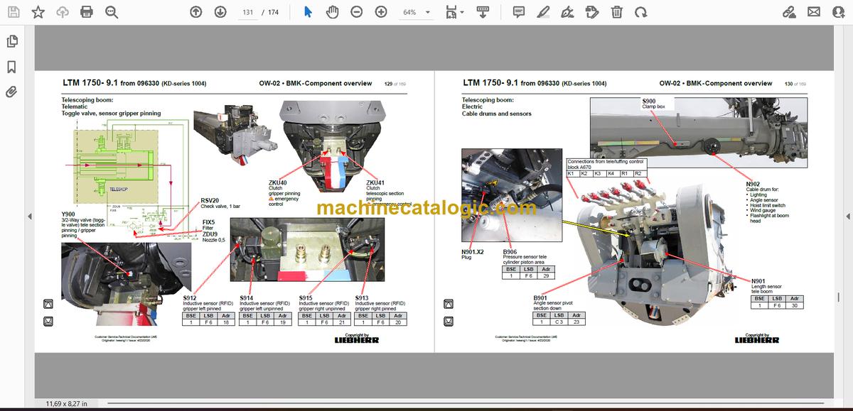
Toggle valve, sensor gripper pinning……………………………………..129
Electric……………………………………………………………………………..130
Cable drums and sensors…………………………………………………….130
Plug, working flood light……………………………………………………….131
Boom head, boom nose……………………………………………………….132
Tele- and luffing cylinder assembly/disassembly………………..133
Control block lifting cylinder and pinning
Tele – slewing platform…………………………………………………………133
Pin puller device tele – slewing platform…………………………………134
Pin puller device luffing cylinder – tele…………………………………….135
Pin puller device slewing platform – luffing cylinder………………….136
Lifting cylinder, clutches lowering brakes………………………………..137
Tele self assembly…………………………………………………………….138
► Additional equipment:……………………………………………………….139
Hydraulic supply TF and TY……………………………………………….139
Copyright by
liebherr
Customer Service-Technical Documentation LWE
Originator: lweeng1 / Issue: 4/22/2020
LTM 1750- 9.1 from 096330 (KD-series 1004) OW-02 • BMK – Component overview 4 of 169
* = Customer‘s spec.
Note:
All stated pressures meet the values of April 2019!
Hydraulic supply TF ………………………………………………………..140
Hydraulically adjustable fixed lattice jib TF………………………..141
TY adapter, hydraulically………………………………………………………141
Clutches, TN-TF adapter……………………………………………………..142
TY adapter, mechanical……………………………………………………….143
N-Head section…………………………………………………………………..144
Auxiliary jib H……………………………………………………………………145
Luffing lattice jib TN………………………………………………………….146
N-assembly unit………………………………………………………………….146
NA-frame 1………………………………………………………………………..148
NA-Frame 3……………………………………………………………………….149
N-pivot section – flap……………………………………………………………150
Fall back protection……………………………………………………………..151
Needle adjusting winch (TN adjustment pulley)……………………….152
TY-suspension………………………………………………………………….153
Overview……………………………………………………………………………153
Transport position, connections…………………………………………….154
Erection cylinder – steep TY-frame sensor………………………………155
Adjustment cylinder – turn sensor………………………………………….156
Valve block for erection and adjustment cylinder……………………..157
Control block – suspension functions……………………………………..158
suspension winch left and right……………………………………………..160
Suspension winch – tooth detection……………………………………….161
Spooling aid – actuation……………………………………………………….162
Spooling aid – turn sensor…………………………………………………….163
Tension cylinder………………………………………………………………….164
► Index………………………………………………………………………………..165


