Format: PDF (Printable Document)
File Language: English
File Pages: 192
File Size: 32.77 MB (Speed Download Link)
Brand: Liebherr
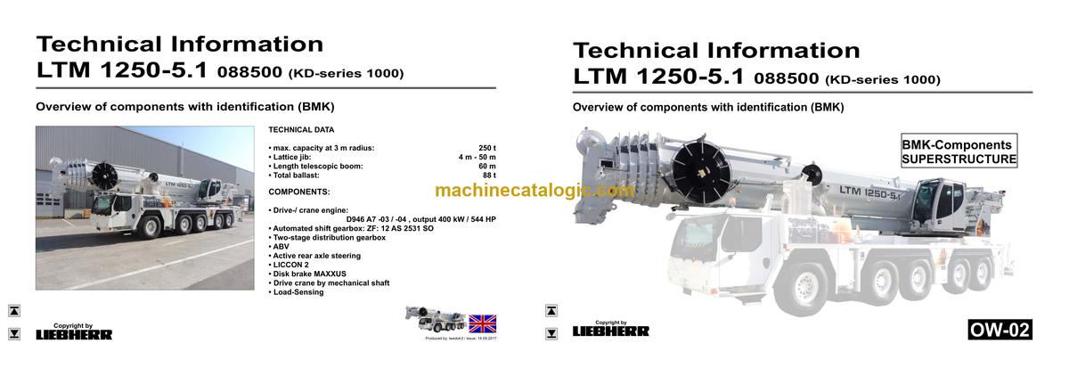
Model: LTM 1250-5.1 Mobile Crane
Components: Carrier + Superstructure
Serial No: SN 088730
Date: 2023
Type of Document: Technical Information & BMK Components Manual
$ 80
The Liebherr LTM 1250-5.1 is a big all‑terrain crane that earns its keep on heavy lifts where downtime is expensive and access is tight. When something electrical or hydraulic acts up, the person who reaches for the BMK / component identification manual is usually the tech with a multimeter in one hand and a laptop or wiring print in the other. Component identification matters because if you can’t find “K15” or “E34” on the actual machine fast, you waste hours just hunting hardware instead of fixing the fault. The Technical Information & BMK Components Manual for Liebherr LTM 1250-5.1 Mobile Crane provides component identification diagrams, reference designators, and visual outlines used by technicians cross‑referencing wiring or hydraulic schematics to physical parts on the crane.
What this manual helps you do
Who this is for
This is for workshop technicians, field service techs, electrical diagnostic engineers, fleet mechanics, and training instructors who already use Liebherr schematics or service info. If you need repair procedures, step‑by‑step troubleshooting, or part numbers, you want a service manual or parts catalogue instead, not this BMK.
FAQ
Q: Is the PDF clear and searchable?
A: Yes, it’s a readable PDF with clear diagrams you can zoom on a laptop or tablet at the jobsite.
Q: Does it cover both the carrier and the superstructure?
A: Yes, it combines BMK information for the lower carrier and upper crane body in one document.
Q: Does it tie into other Liebherr manuals?
A: Yes, these BMK manuals are meant to be used alongside wiring diagrams, hydraulic schematics, service manuals, and parts catalogues for the same machine.
Bottom line: If your main problem is “Where exactly is this component on the LTM 1250-5.1?” then yes, this is exactly what you need. If you’re after how to repair it or what to order, this is not the right book.
►►Chassis:………………………………………………………………………………………….. 4
Lighting front and mirrors…………………………………………………………………..4
Lighting rear…………………………………………………………………………………….5
Side marker lights right………………………………………………………………………6
Side marker lights left………………………………………………………………………..7
Sockets, warning signal sensor…………………………………………………………..8
►►Driver’s cab:…………………………………………………………………………………….. 9
Doors and windows, interior lighting……………………………………………………. 9
Screen wiper and washer…………………………………………………………………10
Heating valves………………………………………………………………………………..10
Ventilation and heat exchanger………………………………………………………… 11
Control elements…………………………………………………………………………….12
Control elements new………………………………………………………………………13
Bluetooth Basic unit – BTB, Bluetooth Terminal – BTT…………………………. 14
Control elements centre console……………………………………………………….15
Centre console – I / O- modules, BTB……………………………………………….. 16
Centre console – batteries, battery main switch, Fuses battery box……….. 17
Centre console – fuses…………………………………………………………………….18
Centre console – relay……………………………………………………………………..19
Centre console – voltage converter, heating flange – control…………………. 20
Center console – components, control units………………………………………..21
Centre console – ventilator, component carrier…………………………………….22
EMERGENCY STOP……………………………………………………………………….22
Centre console – diagnosis plug………………………………………………………..23
Telemetry FMS-interface………………………………………………………………….24
►►Pneumatic system:………………………………………………………………………….25
Air compressor and air dryer…………………………………………………………….25
Pressurised air reservoir Trailer control valve*…………………………………….26
Pneumatic valves in the driver cab……………………………………………………. 27
Brake relay- / overload protection valve…………………………………………….. 28
Filter and overflow valve in circuit IV A,
measuring points compressed air circuits………………………………………….. 29
Pressure sensor and pressure switch for axle suspension and brake system……30
Solenoid valves auxiliary consumer………………………………………………….. 31
Overview disk brake system……………………………………………………………..32
Overview brake pad monitoring…………………………………………………………33
Brake pad monitoring indicator………………………………………………………….34
ABV – control valve………………………………………………………………………….35
ABV – wheel speed sensors……………………………………………………………..36
►►Drive assembly:………………………………………………………………………………37
Complete unit Installation view………………………………………………………….37
View from right……………………………………………………………………………….38
View from left………………………………………………………………………………….39
Copyright by
liebherr
LTM 1250-5.1 088500 (KD-series 1000) UW-02 • BMK – Component overview 2 of 117
Customer Service-Technical Documentation LWE
Produced by: lwedoh3 / Issue: 14.09.2017
►►Diesel engine D946 A7 -04 (Stage IV SCR) / -03 (Powerband H)……….. 40
Engine control unit…………………………………………………………………………..40
Fuel pumps…………………………………………………………………………………….42
Fuel low pressure sensors……………………………………………………………….43
Liebherr Daisy-Chain diesel injection system………………………………………44
Injectors LCR-I S2…………………………………………………………………………..45
Overview exhaust side……………………………………………………………………46
Charge air sensors and preheating…………………………………………………… 47
Exhaust gas flap……………………………………………………………………………..48
Exhaust gas turbo charger with wastegate………………………………………… 49
Overview flywheel side and generator………………………………………………. 50
Speed sensors……………………………………………………………………………….51
Overview fan side……………………………………………………………………………52
Cooling agent…………………………………………………………………………………53
Oil circuit………………………………………………………………………………………..54
Ambient temperature diesel engine…………………………………………………… 55
Terminal resistor CAN-LIDEC (ECU-CAN2)………………………………………..56
Terminal resistor engine-CAN (ECU-CAN2)………………………………………..57
Only Powerband H engines:
External exhaust gas return eAGR……………………………………………………. 58
Intercooler temperature sensor…………………………………………………………59
►►Exhaust gas aftertreatment SCR……………………………………………………..60
Overview exhaust gas system…………………………………………………………..60
Urea tank and tank sensor……………………………………………………………….61
Pump module and AdBlue-lines………………………………………………………..62
AdBlue-injector and upstream-sensors……………………………………………… 63
Downstream sensors……………………………………………………………………….64
Ambient air sensor and exhaust gas flap…………………………………………… 65
►►Air filter unit at engine -03 (Powerband H)………………………………………..66
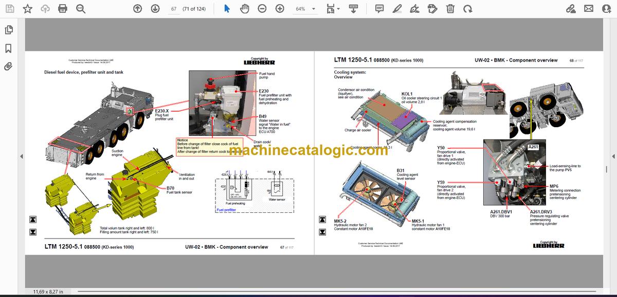
►►Diesel fuel device, prefilter unit and tank…………………………………………67
►►Cooling system:……………………………………………………………………………..68
Overview……………………………………………………………………………………….68
►►Automated shift gearbox ZF 12 AS 2531 SO:……………………………………69
Clutche and gearbox actuator…………………………………………………………..69
Intarder………………………………………………………………………………………….70
►►Hydraulic supply:……………………………………………………………………………71
Overview hydraulic pumps……………………………………………………………….71
Support and axle suspension……………………………………………………………72
Temperature sensor hydraulic oil, hydraulic oil tank……………………………..73
►►Drive train:…………………………………………………………………………………….. 74
Overview……………………………………………………………………………………….74
Distribution gear – Kessler VG 2700 (2-stage)…………………………………….75
Road/off-road switchover…………………………………………………………………76
Switch over travel drive / crane drive (PTO)………………………………………..77
Transversal differential lock axle 2 and 3*………………………………………….. 80
Transversal differential lock axle 4, axle 5………………………………………….. 81
Longitudinal differential lock distribution gear and axle 4,
activation* axle 3 (drive 10×8)…………………………………………………………..82
►►Steering:………………………………………………………………………………………… 83
Steering gear ZF-SERVOCOM, Deficiency monitoring……………………….. 83
Oil supply steering circuit 1, deficiency monitoring……………………………….84
Oil supply steering circuit 2………………………………………………………………85
►►Active rear axle steering:…………………………………………………………………86
Flow and pressure monitoring…………………………………………………………..86
CAN-Valves (HAWE)……………………………………………………………………….87
Control block………………………………………………………………………………….88
Measuring points…………………………………………………………………………….89
Angle sensor………………………………………………………………………………….90
Steering- and centering cylinder, safety valves……………………………………91
►►Support………………………………………………………………………………………….. 92
Inclination sensor……………………………………………………………………………92
Support valves – right………………………………………………………………………93
Support valves – left…………………………………………………………………………94
Sliding beam sliding beam……………………………………………………………….95
Support cylinder……………………………………………………………………………..97
Sliding beam monitoring…………………………………………………………………..98
►►Axle suspension:…………………………………………………………………………….99
Level sensor- axle suspension………………………………………………………….99
Control valve – blocked / sprung………………………………………………………100
Valve block – axle suspension right…………………………………………………. 101
Valve block – axle suspension left……………………………………………………102
Axle suspensions cylinder………………………………………………………………103
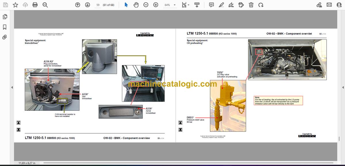
►►Special equipment:……………………………………………………………………….104
Eddy currant brake Telma Focal 2200*……………………………………………. 104
Variable support*…………………………………………………………………………..105
Supporting force sensor – plug connections*……………………………………..106
Vario Base with pressure sensor*……………………………………………………107
Air condition*………………………………………………………………………………..108
External power supply 24 V*, socket 110 / 230 V*……………………………..109
Back-up camera*…………………………………………………………………………..109
Additional heating Thermo PRO 90*……………………………………………….. 110
Additional heating Airtop 2000 ST*……………………………………………………111
External power supply*………………………………………………………………….. 112
Battery charger*…………………………………………………………………………… 113
Emergency control cran hydraulic* – vehicle…………………………………….. 114
►► Index……………………………………………………………………………………………. 115


