Format: PDF (Printable Document)
File Language: English
File Pages: 104
File Size: 28.26 MB (Speed Download Link)
Brand: Liebherr
Model: MK 88 Mobile Construction Crane
Components: Carrier
Serial No: SN 047324
Date: 2023
Type of Document: Technical Information & BMK Components Manual
$ 50
The Liebherr MK 88 Mobile Construction Crane spends its life on tight urban sites, where downtime is expensive and access is cramped. When something electrical or hydraulic on the carrier acts up, the first people reaching for the Liebherr BMK component identification manual are techs chasing a relay, a valve block, or a connector number from a schematic. Knowing exactly where “that box” sits on the chassis is what keeps your workshop from wasting an hour just hunting around the machine. This Technical Information & BMK Components Manual for SN 047324 is built for that job, but it’s not a repair book.
What this manual helps you do
Who this is for
This is aimed at workshop technicians, field service techs, electrical diagnostic engineers, fleet mechanics, and training instructors who already have or plan to use the service, parts, and wiring documentation. If you need step‑by‑step repair procedures, torque specs, or part numbers, you need a service manual and a parts catalogue instead of this BMK.
FAQ
Q: Are the diagrams clear and searchable in the PDF?
A: You’ll typically get clear carrier layout diagrams and searchable text so you can jump straight to a component ID or reference designator.
Q: Does this cover the whole crane or just part of it?
A: This BMK manual only covers the carrier of the Liebherr MK 88 Mobile Construction Crane, not the upper crane body, boom, or superstructure.
Q: Does it work together with other Liebherr manuals?
A: Yes, this kind of BMK is meant to be used alongside wiring diagrams, service manuals, and parts catalogues so you can go from fault code or schematic symbol to the exact physical part.
Bottom line: If your main question is “Where is this carrier component on the MK 88, and what does Liebherr call it?”, this is the right manual. If you’re after how to fix it or which part number to order, this is not what you need.
Table of contents
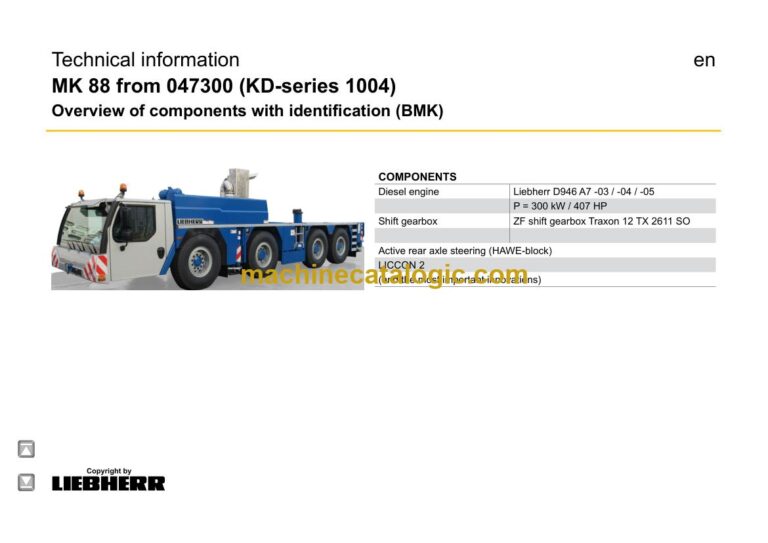
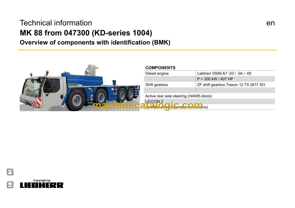
Technical information
MK 88 from 047300 (KD-series 1004)
Overview of components with identification (BMK)
en
► Chassis:……………………………………………………………………………….3
Lighting front and mirrors…………………………………………………………3
Lighting rear…………………………………………………………………………..4
Side view right and left…………………………………………………………….5
Sockets, warning signal sensor, button EMERGENCY STOP……….6
► Driver cab:……………………………………………………………………………8
Doors and windows, interior lighting………………………………………….8
Heating valves, screen wiper and washer………………………………….9
Ventilation and heat exchanger………………………………………………10
Control elements………………………………………………………………….. 11
Control elements centre console…………………………………………….12
BTB, Remote control module BTT………………………………………….13
Centre console – battery box, fuses…………………………………………14
Centre console – fuses…………………………………………………………..15
Centre console – I/O- modules, ECUs……………………………………..16
Centre console – relay……………………………………………………………17
Centre console – relays, fan, component carrier, resistor module..18
Centre console – voltage converter relay heating flange…………….19
Centre console – diagnosis plug, EMERGENCY STOP………………20
► Pneumatic system:……………………………………………………………..21
Air compressor and air dryer………………………………………………….21
Pressure reservoir………………………………………………………………..22
Pressure sensors and pressure switches…………………………………23
Solenoid valve for auxiliary users……………………………………………24
ABV – regulating valves…………………………………………………………25
Compressed air circuits – measuring points………………………………26
Disk brake system ……………………………………………………………….27
Overview brake pad control……………………………………………………28
Brake pad monitoring indicator……………………………………………….29
Brake relay-, overload protection valve……………………………………30
► Diesel engine D946 A7 -03 (eAGR) 04 (SCR) / -05 (SCRF):…….31
Overview drive assembly……………………………………………………….31
Installation diesel engine……………………………………………………….32
Engine control unit………………………………………………………………..33
Overview injection side………………………………………………………….34
Fuel pumps………………………………………………………………………….35
Fuel low pressure sensors……………………………………………………..36
Liebherr Daisy-Chain diesel injection system……………………………37
Injectors LCR-I S2………………………………………………………………..38
Type plates:…………………………………………………………………………38
Overview exhaust gas side…………………………………………………….39
Charge air sensors and -preheating………………………………………..40
Exhaust gas flap…………………………………………………………………..41
Exhaust gas turbo charger with wastegate……………………………….42
Overview flywheel side and generator……………………………………..43
Speed sensors……………………………………………………………………..44
Overview fan side…………………………………………………………………45
Cooling agent……………………………………………………………………….46
Oil circuit……………………………………………………………………………..47
Copyright by
liebherr
LWE – Customer Service – Documentation
Author: lweeng1 / Issue: 1/17/2020
MK 88 from 047300 (KD-series 1004) UW-02 • BMK – Overview of components 2 of 98
* = Customer‘s spec.
Note:
All stated pressures meet the values of April 2018!
Terminal resistor CAN-LIDEC (ECU-CAN2)……………………………..48
Terminal resistor engine-CAN (ECU-CAN2)……………………………..49
Diesel engine D946 A7 -03 (eAGR) / Power Band H:…………………50
External exhaust gas return eAGR………………………………………….50
Intercooler temperature sensor……………………………………………….51
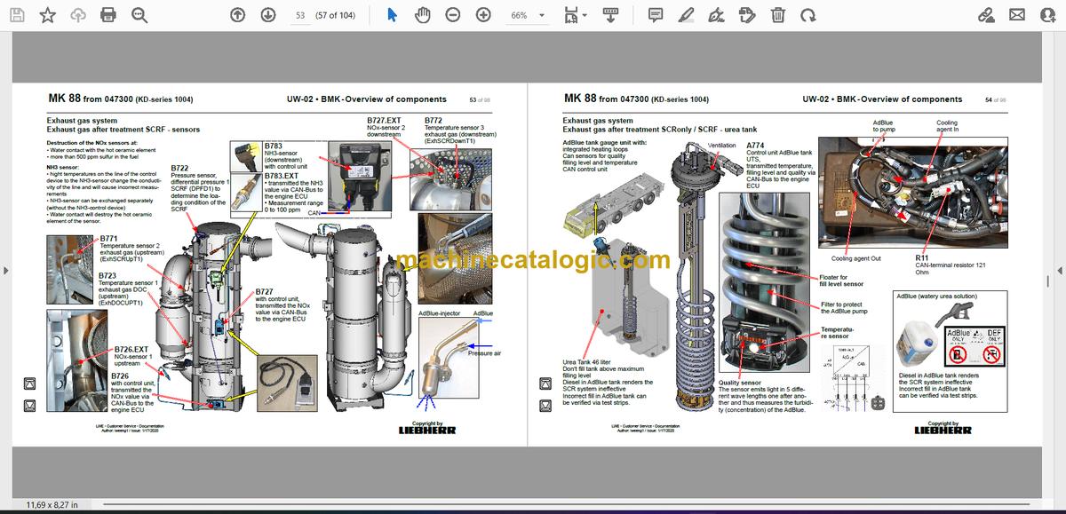
► Exhaust gas system……………………………………………………………52
Exhaust gas after treatment SCRF – overview………………………….52
Exhaust gas after treatment SCRF – sensors……………………………53
Exhaust gas after treatment SCRonly / SCRF – urea tank………….54
Exhaust gas after treatment SCRonly / SCRF – tank sensor, lines.55
Exhaust gas after treatment SCRonly / SCRF – SCR pump module.. 56
Exhaust gas after treatment SCRonly / SCRF- exhaust gas flap…57
► Air filter system…………………………………………………………………..58
Air filter vacuum, shut off flap in suction air *…………………………….58
► Fuel system:……………………………………………………………………….59
Fuel prefilter and tank……………………………………………………………59
► Cooling system…………………………………………………………………..60
Cooler installation…………………………………………………………………60
► ZF shift gearbox Traxon 12 TX 2611 SO……………………………….61
Gearbox control……………………………………………………………………61
Intarder……………………………………………………………………………….62
► Hydraulic:…………………………………………………………………………..63
Hydraulic oil tank, temperature sensor and flow switch hydraulic oil.. 63
Hydraulic pumps – overview……………………………………………………64
► Drive train:………………………………………………………………………….65
Overview, shifting conditions………………………………………………….65
Distribution gearbox Kessler VG 2700 (two stage)…………………….66
Distribution gearbox – switch position………………………………………67
Transversal differential lock axle 2…………………………………………..67
Long.- and transv. differential lock…………………………………………..68
ABV, wheel speed sensors…………………………………………………….69
► Steering:…………………………………………………………………………….70
Oil supply, deficiency monitoring……………………………………………..71
Deficiency monitoring, metering connection centering pressure….72
► Active rear axle steering……………………………………………………..73
CAN-Valves (HAWE)…………………………………………………………….73
Measuring connections MP6, MP11………………………………………..75
Angle sensor………………………………………………………………………..76
Steering- and centering cylinder……………………………………………..77
► Support………………………………………………………………………………78
Inclination sensor………………………………………………………………….78
Support valves – right…………………………………………………………….79
Support valves – left………………………………………………………………80
Extension cylinder sliding beam……………………………………………..81
Support cylinder……………………………………………………………………82
Vario Base – sliding beam monitoring with rope length sensor…….83
Vario Base – monitoring………………………………………………………….84
► Axle suspension:………………………………………………………………..85
Level sensor- axle suspension……………………………………………….85
Valves for axle pressure compensation, blocked/sprung…………….86
Valve block – axle suspension right………………………………………….87
Valve block – axle suspension left……………………………………………88
► Special equipment:……………………………………………………………..89
Additional heating Thermo Pro 90…………………………………………..89
Air-conditioner………………………………………………………………………90
Device carrier* – lighting – hydraulic connection…………………………91
Device carrier* – hydraulic………………………………………………………92
Battery charger…………………………………………………………………….93
Camera color……………………………………………………………………….94


