Format: PDF (Printable Document)
File Language: English
File Pages: 30
File Size: 1.22 MB (Speed Download Link)
Brand: Komatsu
Model: PC160LC-7E0 PC180LC-7E0 PC180NLC-7E0
Book No: UEN01892-04
Serial No: K45001 and up
Type of Document: Shop Manual
$ 39
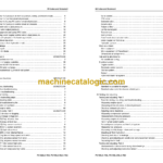
Table of contents 1
00 Index and foreword
Index UEN01894-04
Composition of shop manual…………………………………………………………………………………………. 2
Table of contents …………………………………………………………………………………………………………. 4
Foreword and general information UEN01895-01
Safety notice……………………………………………………………………………………………………………….. 2
How to read the shop manual ……………………………………………………………………………………….. 7
Explanation of terms for maintenance standard……………………………………………………………….. 9
Handling electric equipment and hydraulic component……………………………………………………… 11
How to read electric wire code ………………………………………………………………………………………. 23
Precautions when carrying out operation ………………………………………………………………………… 26
Method of disassembling and connecting push-pull type coupler ……………………………………….. 29
Standard tightening torque table ……………………………………………………………………………………. 32
Conversion table …………………………………………………………………………………………………………. 36
01 Specification
Specification and technical data UEN01897-00
Specification dimension drawings ………………………………………………………………………………….. 2
Specifications ……………………………………………………………………………………………………………… 4
Weight table ……………………………………………………………………………………………………………….. 6
Table of fuel, coolant and lubricants ……………………………………………………………………………….. 8
10 Structure, function and maintenance standard
Engine and cooling system UEN01899-00
Engine related parts …………………………………………………………………………………………………….. 2
Radiator, oil cooler, aftercooler and fuel cooler ………………………………………………………………… 3
Power train system UEN01900-00
Power train …………………………………………………………………………………………………………………. 2
Swing circle ………………………………………………………………………………………………………………… 3
Swing machinery …………………………………………………………………………………………………………. 4
Final drive…………………………………………………………………………………………………………………… 6
Sprocket …………………………………………………………………………………………………………………….. 8
Undercarriage and frame UEN01901-00
Track frame, recoil spring ……………………………………………………………………………………………… 2
Idler …………………………………………………………………………………………………………………………… 4
Carrier roller ……………………………………………………………………………………………………………….. 6
Track roller………………………………………………………………………………………………………………….. 7
Track shoe………………………………………………………………………………………………………………….. 8
Hydraulic system, Part 1 UEN01902-00
Hydraulic equipment layout drawing ………………………………………………………………………………. 2
Hydraulic tank……………………………………………………………………………………………………………… 4
Hydraulic pump …………………………………………………………………………………………………………… 6
Hydraulic system, Part 2 UEN01903-00
Control valve ………………………………………………………………………………………………………………. 2
CLSS…………………………………………………………………………………………………………………………. 16
Functions and operation by valve…………………………………………………………………………………… 20
Hydraulic drift prevention valve ……………………………………………………………………………………… 44
Hydraulic system, Part 3 UEN01967-01
00 Index and foreword UEN01894-04
PC160LC-7E0, PC180LC/NLC-7E0 5
Valve control……………………………………………………………………………………………………………….. 2
PPC valve ………………………………………………………………………………………………………………….. 3
Solenoid valve…………………………………………………………………………………………………………….. 20
Accumulator ……………………………………………………………………………………………………………….. 22
Return oil filter …………………………………………………………………………………………………………….. 23
Centre swivel joint ……………………………………………………………………………………………………….. 24
Travel motor ……………………………………………………………………………………………………………….. 25
Swing motor ……………………………………………………………………………………………………………….. 35
Attachment circuit selector valve……………………………………………………………………………………. 36
Quick coupler control valve …………………………………………………………………………………………… 40
Hydraulic cylinder………………………………………………………………………………………………………… 42
Work equipment UEN01904-01
Work equipment ………………………………………………………………………………………………………….. 2
Work equipment (2 Piece Boom) …………………………………………………………………………………… 3
Dimensions of components…………………………………………………………………………………………… 6
Cab and its attachments UEN01905-00
Air conditioner piping……………………………………………………………………………………………………. 2
Electrical system UEN01906-00
Engine control …………………………………………………………………………………………………………….. 2
Electronic control system ……………………………………………………………………………………………… 11
Monitor system……………………………………………………………………………………………………………. 37
Sensor……………………………………………………………………………………………………………………….. 55
KOMTRAX terminal system ………………………………………………………………………………………….. 58
20 Standard value table
Standard service value table UEN02107-00
Standard value table for engine …………………………………………………………………………………….. 2
Standard value table for chassis related parts …………………………………………………………………. 3
30 Testing and adjusting
Testing and adjusting, Part 1 UEN02108-00
Tools for testing, adjusting, and troubleshooting ………………………………………………………………. 2
Measuring engine speed………………………………………………………………………………………………. 5
Measuring intake air pressure (boost pressure)……………………………………………………………….. 6
Checking exhaust gas colour ………………………………………………………………………………………… 7
Adjusting valve clearance …………………………………………………………………………………………….. 8
Measuring compression pressure ………………………………………………………………………………….. 10
Measurement of blow-by pressure…………………………………………………………………………………. 12
Measuring engine oil pressure ………………………………………………………………………………………. 13
Handling fuel system parts……………………………………………………………………………………………. 14
Releasing residual pressure from fuel system …………………………………………………………………. 14
Measuring fuel pressure……………………………………………………………………………………………….. 15
Measuring fuel discharge, return and leakage …………………………………………………………………. 17
Bleeding air from fuel circuit………………………………………………………………………………………….. 21
Checking fuel circuit for leakage ……………………………………………………………………………………. 23
Checking and adjusting air conditioner compressor belt tension ………………………………………… 24
Replacing the fan belt ………………………………………………………………………………………………….. 25
Testing and adjusting, Part 2 UEN02109-01
Measurement of clearance in swing circle bearings …………………………………………………………. 2
Checking and adjusting track shoe tension……………………………………………………………………… 3
Inspection and adjustment oil pressure in work equipment, swing, and travel circuits …………… 4
Inspection and adjustment of control circuit oil pressure……………………………………………………. 7
Inspection and adjustment of pump PC control circuit oil pressure……………………………………… 8
Inspection and adjustment of pump LS control circuit oil pressure ……………………………………… 11
Measurement of solenoid valve output pressure………………………………………………………………. 15
Measurement of PPC valve output pressure……………………………………………………………………. 18
Adjustment of work equipment and swing PPC valve ……………………………………………………….. 19
Measuring and adjusting quick coupler control valve output pressure…………………………………. 20
Inspection of locations of hydraulic drift of work equipment ……………………………………………….. 21
Testing and adjusting travel deviation …………………………………………………………………………….. 23
Release of residual pressure from hydraulic circuit…………………………………………………………… 25
Measurement of oil leakage ………………………………………………………………………………………….. 26
Bleeding air from each part …………………………………………………………………………………………… 28
Inspection procedures for diode …………………………………………………………………………………….. 30
Adjusting mirrors …………………………………………………………………………………………………………. 31
Testing and adjusting, Part 3 UEN02110-00
Special functions of machine monitor……………………………………………………………………………… 2
Handling voltage circuit of engine controller…………………………………………………………………….. 30
Procedure for turning on KOMTRAX terminal ………………………………………………………………….. 31
Indication by KOMTRAX terminal lamps …………………………………………………………………………. 34
Preparation work for troubleshooting of electrical system………………………………………………….. 37
40 Troubleshooting
Failure code table and fuse locations UEN02111-00
Failure code table………………………………………………………………………………………………………… 2
Fuse locations …………………………………………………………………………………………………………….. 5
General information on troubleshooting UEN02112-00
Points to remember when troubleshooting………………………………………………………………………. 2
Sequence of events in troubleshooting …………………………………………………………………………… 3
Checks before troubleshooting………………………………………………………………………………………. 4
Classification and troubleshooting steps …………………………………………………………………………. 5
Information in troubleshooting table ……………………………………………………………………………….. 6
Possible problems and troubleshooting No……………………………………………………………………… 8
Wiring table for connector pin numbers…………………………………………………………………………… 11
T-adapter box and T-adapter table …………………………………………………………………………………. 40
Troubleshooting by failure code, Part 1 UEN02113-00
Failure code [AA10NX] Air cleaner clogging ……………………………………………………………………. 3
Failure code [AB00KE] Charge voltage low …………………………………………………………………….. 4
Failure code [B@BAZG] Eng. oil press. low…………………………………………………………………….. 6
Failure code [B@BAZK] Eng. oil level low ………………………………………………………………………. 7
Failure code [B@BCNS] Eng. coolant overheat……………………………………………………………….. 8
Failure code [B@BCZK] Eng. coolant level low ……………………………………………………………….. 10
Failure code [B@HANS] Hydr oil overheat ……………………………………………………………………… 12
Failure code [CA111] EMC critical internal failure …………………………………………………………….. 12
Failure code [CA115] Eng Ne and bkup speed sens error …………………………………………………. 13
Failure code [CA122] Chg air press sensor high error ………………………………………………………. 15
Failure code [CA123] Chg air press sensor low error ……………………………………………………….. 17
Failure code [CA131] Throttle sensor high error ………………………………………………………………. 19
Failure code [CA132] Throttle sensor low error………………………………………………………………… 21
Failure code [CA144] Coolant temp sens high error …………………………………………………………. 23
00 Index and foreword UEN01894-04
PC160LC-7E0, PC180LC/NLC-7E0 7
Failure code [CA145] Coolant temp sens low error ………………………………………………………….. 25
Failure code [CA153] Chg air temp sensor high error……………………………………………………….. 27
Failure code [CA154] Chg air temp sensor low error ………………………………………………………… 29
Failure code [CA155] Chg air temp high speed derate ……………………………………………………… 31
Failure code [CA187] Sens supply 2 volt low error …………………………………………………………… 33
Failure code [CA221] Ambient press sens high error ……………………………………………………….. 35
Failure code [CA222] Ambient press sens low error…………………………………………………………. 37
Failure code [CA227] Sens supply 2 volt high error………………………………………………………….. 39
Failure code [CA234] Eng. overspeed ……………………………………………………………………………. 40
Failure code [CA238] Ne speed sens supply volt error……………………………………………………… 41
Failure code [CA271] IMV/PCV1 short error ……………………………………………………………………. 42
Failure code [CA272] IMV/PCV1 open error ……………………………………………………………………. 43
Failure code [CA322] Inj #1 open/short error …………………………………………………………………… 45
Failure code [CA324] Inj #3 open/short error …………………………………………………………………… 47
Troubleshooting by failure code, Part 2 UEN02114-00
Failure code [CA331] Inj #2 open/short error …………………………………………………………………… 4
Failure code [CA332] Inj #4 open/short error …………………………………………………………………… 6
Failure code [CA342] Calibration code incompatibility ………………………………………………………. 8
Failure code [CA351] Injectors drive circuit error ……………………………………………………………… 10
Failure code [CA352] Sens supply 1 volt low error …………………………………………………………… 12
Failure code [CA386] Sens supply 1 volt high error………………………………………………………….. 14
Failure code [CA428] Water in fuel sensor high error ……………………………………………………….. 16
Failure code [CA429] Water in fuel sensor low error…………………………………………………………. 18
Failure code [CA435] Eng oil press sw error……………………………………………………………………. 20
Failure code [CA441] Engine controller battery voltage low error ……………………………………….. 22
Failure code [CA442] Engine controller battery voltage high error ……………………………………… 24
Failure code [CA449] Rail press very high error ………………………………………………………………. 26
Failure code [CA451] Rail press sensor high error …………………………………………………………… 28
Failure code [CA452] Rail press sensor low error…………………………………………………………….. 30
Failure code [CA488] Chg air temp high torque derate……………………………………………………… 32
Failure code [CA553] Rail press high error ……………………………………………………………………… 32
Failure code [CA559] Rail press low error ………………………………………………………………………. 33
Failure code [CA689] Eng Ne speed sensor error ……………………………………………………………. 34
Failure code [CA731] Eng Bkup speed sens phase error ………………………………………………….. 36
Failure code [CA757] All continuous data lost error………………………………………………………….. 38
Failure code [CA778] Eng Bkup speed sensor error…………………………………………………………. 40
Failure code [CA1633] KOMNET Datalink timeout error……………………………………………………. 42
Failure code [CA2185] Throt sens sup volt high error……………………………………………………….. 44
Failure code [CA2186] Throt sens sup volt low error ………………………………………………………… 45
Failure code [CA2249] Rail press very low error………………………………………………………………. 46
Failure code [CA2311] IMV solenoid error ………………………………………………………………………. 48
Failure code [CA2555] Grid htr relay volt high error………………………………………………………….. 50
Failure code [CA2556] Grid htr relay volt low error …………………………………………………………… 52
Troubleshooting by failure code, Part 3 UEN02115-00
Failure code [D110KB] Battery relay drive S/C ………………………………………………………………… 2
Failure code [D196KA] Service return relay disc. …………………………………………………………….. 4
Failure code [D196KB] Service return relay S/C………………………………………………………………. 6
Failure code [DA22KK] Pump solenoid power low error ……………………………………………………. 8
Failure code [DA25KP] Press. sensor power abnormality …………………………………………………. 10
Failure code [DA2RMC] Pump comm. abnormality ………………………………………………………….. 12
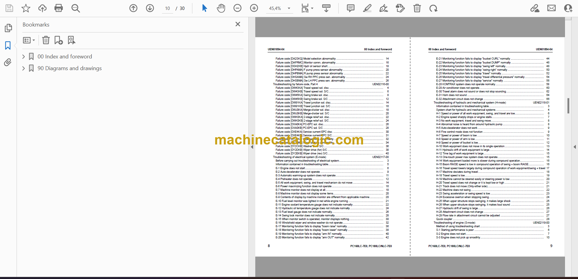
Failure code [DA2SKQ] Model selection abnormality ……………………………………………………….. 14
Failure code [DAFRMC] Monitor comm. abnormality………………………………………………………… 16
Failure code [DGH2KB] Hydr oil sensor short………………………………………………………………….. 18
Failure code [DHPAMA] F pump press sensor abnormality ……………………………………………….. 20
Failure code [DHPBMA] R pump press sensor abnormality ………………………………………………. 22
Failure code [DHSAMA] Sw RH PPC press sen. abnormality ……………………………………………. 24
Failure code [DHSBMA] Sw LH PPC press sen. abnormality …………………………………………….. 26
Troubleshooting by failure code, Part 4 UEN02116-00
Failure code [DW43KA] Travel speed sol. disc. ……………………………………………………………….. 4
Failure code [DW43KB] Travel speed sol. S/C…………………………………………………………………. 6
Failure code [DW45KA] Swing brake sol. disc. ………………………………………………………………… 8
Failure code [DW45KB] Swing brake sol. S/C …………………………………………………………………. 12
Failure code [DW91KA] Travel junction sol. disc………………………………………………………………. 14
Failure code [DW91KB] Travel junction sol. S/C………………………………………………………………. 16
Failure code [DWJ0KA] Merge-divider sol. disc ……………………………………………………………….. 18
Failure code [DWJ0KB] Merge-divider sol. S/C ……………………………………………………………….. 20
Failure code [DWK0KA] 2-stage relief sol. disc………………………………………………………………… 22
Failure code [DWK0KB] 2-stage relief sol. S/C ………………………………………………………………… 24
Failure code [DXA0KA] PC-EPC sol. disc……………………………………………………………………….. 26
Failure code [DXA0KB] PC-EPC sol. S/C ……………………………………………………………………….. 28
Failure code [DXE4KA] Service current EPC disc. …………………………………………………………… 30
Failure code [DXE4KB] Service current EPC S/C…………………………………………………………….. 31
Failure code [DY20KA] Wiper working abnormality ………………………………………………………….. 32
Failure code [DY20MA] Wiper parking abnormality ………………………………………………………….. 34
Failure code [DY2CKB] Washer drive S/C ………………………………………………………………………. 36
Failure code [DY2DKB] Wiper drive (for) S/C ………………………………………………………………….. 38
Failure code [DY2EKB] Wiper drive (rev) S/C………………………………………………………………….. 40
Troubleshooting of electrical system (E-mode) UEN02117-00
Before carrying out troubleshooting of electrical system……………………………………………………. 3
Information contained in troubleshooting table…………………………………………………………………. 5
E-1 Engine does not start……………………………………………………………………………………………… 6
E-2 Auto-decelerator does not operate …………………………………………………………………………… 9
E-3 Automatic warming-up system does not operate………………………………………………………… 11
E-4 Preheater does not operate …………………………………………………………………………………….. 12
E-5 All work equipment, swing, and travel mechanism do not move …………………………………… 14
E-6 Power maximizing function does not operate …………………………………………………………….. 16
E-7 Machine monitor does not display at all…………………………………………………………………….. 18
E-8 Machine monitor does not display some items…………………………………………………………… 20
E-9 Contents of display by machine monitor are different from applicable machine………………. 20
E-10 Fuel level monitor was lighted in red while engine running ………………………………………… 21
E-11 Engine coolant temperature gauge does not indicate normally …………………………………… 22
E-12 Hydraulic oil temperature gauge does not indicate normally ………………………………………. 24
E-13 Fuel level gauge does not indicate normally…………………………………………………………….. 26
E-14 Swing lock monitor does not indicate normally…………………………………………………………. 28
E-15 When monitor switch is operated, monitor displays nothing……………………………………….. 30
E-16 Windshield wiper and window washer do not operate……………………………………………….. 32
E-17 Monitoring function fails to display “boom raise” normally ………………………………………….. 36
E-18 Monitoring function fails to display “boom lower” normally …………………………………………. 38
E-19 Monitoring function fails to display “arm IN” normally ………………………………………………… 40
E-20 Monitoring function fails to display “arm OUT” normally …………………………………………….. 42
00 Index and foreword UEN01894-04
PC160LC-7E0, PC180LC/NLC-7E0 9
E-21 Monitoring function fails to display “bucket CURL” normally ………………………………………. 44
E-22 Monitoring function fails to display “bucket DUMP” normally ……………………………………… 46
E-23 Monitoring function fails to display “swing left” normally…………………………………………….. 48
E-24 Monitoring function fails to display “swing right” normally ………………………………………….. 50
E-25 Monitoring function fails to display “travel” normally………………………………………………….. 52
E-26 Monitoring function fails to display “travel differential pressure” normally …………………….. 54
E-27 Monitoring function fails to display “service” normally ……………………………………………….. 56
E-28 KOMTRAX system does not operate normally…………………………………………………………. 58
E-29 Air conditioner does not operate…………………………………………………………………………….. 60
E-30 Travel alarm does not sound or does not stop sounding……………………………………………. 62
E-31 Horn does not sound ……………………………………………………………………………………………. 64
E-32 Attachment circuit does not change ……………………………………………………………………….. 66
Troubleshooting of hydraulic and mechanical system (H-mode) UEN02118-01
Information contained in troubleshooting table…………………………………………………………………. 3
System chart for hydraulic and mechanical systems ………………………………………………………… 4
H-1 Speed or power of all work equipment, swing, and travel are low…………………………………. 6
H-2 Engine speed sharply drops or engine stalls……………………………………………………………… 7
H-3 No work equipment, travel and swing move………………………………………………………………. 8
H-4 Abnormal noise is heard from around hydraulic pump………………………………………………… 8
H-5 Auto-decelerator does not work ………………………………………………………………………………. 9
H-6 Fine control mode does not function ………………………………………………………………………… 9
H-7 Speed or power of boom is low ……………………………………………………………………………….. 10
H-8 Speed or power of arm is low ………………………………………………………………………………….. 11
H-9 Speed or power of bucket is low………………………………………………………………………………. 12
H-10 Work equipment does not move in its single operation ……………………………………………… 13
H-11 Hydraulic drift of work equipment is large………………………………………………………………… 14
H-12 Time lag of work equipment is large……………………………………………………………………….. 15
H-13 One-touch power max system does not operate………………………………………………………. 15
H-14 Work equipment loaded more is slower during compound operation…………………………… 16
H-15 Boom RAISE speed is low in compound operation of swing + boom RAISE………………… 16
H-16 Travel speed lowers largely during compound operation of work equipment/swing + travel 17
H-17 Machine deviates during travel………………………………………………………………………………. 18
H-18 Travel speed is low………………………………………………………………………………………………. 19
H-19 Machine cannot be steered easily or steering power is low ……………………………………….. 20
H-20 Travel speed does not change or it is kept low or high ……………………………………………… 21
H-21 Track does not move (Only either side)…………………………………………………………………… 21
H-22 Machine does not swing……………………………………………………………………………………….. 22
H-23 Swing acceleration or swing speed is low ……………………………………………………………….. 23
H-24 Excessive overrun when stopping swing…………………………………………………………………. 24
H-25 When upper structure stops swinging, it makes large shock ……………………………………… 25
H-26 When upper structure stops swinging, it makes loud sound ………………………………………. 25
H-27 Hydraulic drift of swing is large………………………………………………………………………………. 26
H-28 Attachment circuit does not change ……………………………………………………………………….. 27
H-29 Flow rate in attachment circuit cannot be adjusted …………………………………………………… 27
Quick coupler ……………………………………………………………………………………………………………… 28
Troubleshooting of engine (S-mode) UEN02119-00
Method of using troubleshooting chart ……………………………………………………………………………. 3
S-1 Starting performance is poor …………………………………………………………………………………… 6
S-2 Engine does not start……………………………………………………………………………………………… 7
S-3 Engine does not pick up smoothly……………………………………………………………………………. 10
S-4 Engine stops during operations ……………………………………………………………………………….. 11
S-5 Engine does not rotate smoothly ……………………………………………………………………………… 12
S-6 Engine lack output (or lacks power)………………………………………………………………………….. 13
S-7 Exhaust smoke is black (incomplete combustion) ………………………………………………………. 14
S-8 Oil consumption is excessive (or exhaust smoke is blue) ……………………………………………. 15
S-9 Oil becomes contaminated quickly …………………………………………………………………………… 16
S-10 Fuel consumption is excessive ………………………………………………………………………………. 17
S-11 Oil is in coolant (or coolant spurts back or coolant level goes down)……………………………. 18
S-12 Oil pressure drops ……………………………………………………………………………………………….. 19
S-13 Oil level rises (Entry of coolant/fuel) ……………………………………………………………………….. 20
S-14 Coolant temperature becomes too high (overheating) ………………………………………………. 21
S-15 Abnormal noise is made ……………………………………………………………………………………….. 22
S-16 Vibration is excessive …………………………………………………………………………………………… 23
50 Disassembly and assembly
General information on disassembly and assembly UEN02447-00
How to read this manual……………………………………………………………………………………………….. 2
List of adhesives………………………………………………………………………………………………………….. 4
Special tool list…………………………………………………………………………………………………………….. 7
Sketches of special tools………………………………………………………………………………………………. 10
Engine and cooling system UEN02448-00
Removal and installation of fuel supply pump assembly……………………………………………………. 2
Removal and installation of fuel injector assembly……………………………………………………………. 5
Removal and installation of front oil seal…………………………………………………………………………. 10
Removal and installation of rear oil seal………………………………………………………………………….. 12
Removal and installation of cylinder head assembly…………………………………………………………. 15
Removal and installation of radiator assembly…………………………………………………………………. 25
Removal and installation of aftercooler assembly …………………………………………………………….. 27
Removal and installation of work equipment oil cooler assembly ……………………………………….. 29
Removal and installation of engine and hydraulic pump assembly……………………………………… 31
Removal and installation of engine hood assembly ………………………………………………………….. 38
Removal and installation of fuel tank assembly ……………………………………………………………….. 40
Power train UEN02449-00
Removal and installation of travel motor and final drive assembly………………………………………. 2
Disassembly and assembly of final drive assembly ………………………………………………………….. 3
Removal and installation of swing motor and swing machinery assembly……………………………. 10
Disassembly and assembly of swing motor and swing machinery assembly ……………………….. 12
Removal and installation of swing circle assembly …………………………………………………………… 20
Undercarriage and frame UEN02450-00
Disassembly and assembly of carrier roller……………………………………………………………………… 2
Disassembly and assembly of track roller assembly…………………………………………………………. 5
Disassembly and assembly of idler assembly………………………………………………………………….. 7
Disassembly and assembly of recoil spring …………………………………………………………………….. 10
Expansion and installation of track shoe assembly …………………………………………………………… 12
Removal and installation of sprocket………………………………………………………………………………. 14
Removal and installation of revolving frame assembly ……………………………………………………… 15
Removal and installation of counterweight………………………………………………………………………. 17
Hydraulic system UEN02451-01
Removal and installation of centre swivel joint assembly…………………………………………………… 2
Disassembly and assembly of centre swivel joint assembly ………………………………………………. 4
00 Index and foreword UEN01894-04
PC160LC-7E0, PC180LC/NLC-7E0 11
Removal and installation of hydraulic tank assembly………………………………………………………… 5
Removal and installation of hydraulic pump assembly ……………………………………………………… 8
Removal and installation of control valve assembly………………………………………………………….. 11
Disassembly and assembly of control valve assembly ……………………………………………………… 15
Removal and installation of hydraulic pump input shaft oil seal ………………………………………….. 17
Disassembly and assembly of work equipment PPC valve assembly …………………………………. 18
Disassembly and assembly of travel PPC valve assembly………………………………………………… 19
Disassembly and assembly of hydraulic cylinder assembly……………………………………………….. 20
Disassembly and Assembly of Quick Coupler Valve…………………………………………………………. 26
Work equipment Body UEN02452-00
Removal and installation of work equipment assembly …………………………………………………….. 2
Cab and its attachments UEN02453-00
Removal and installation of operator’s cab ……………………………………………………………………… 2
Removal and installation of operator’s cab glass (Stuck glass) ………………………………………….. 5
Removal and installation of front window assembly………………………………………………………….. 16
Removal and installation of floor frame assembly…………………………………………………………….. 22
Electrical system UEN02454-00
Removal and installation of air conditioner compressor assembly ……………………………………… 2
Removal and installation of air conditioner condenser………………………………………………………. 3
Removal and installation of air conditioner unit assembly …………………………………………………. 4
Removal and installation of machine monitor assembly ……………………………………………………. 6
Removal and installation of governor, pump controller assembly ……………………………………….. 7
Removal and installation of engine controller assembly ……………………………………………………. 8
Removal and installation of KOMTRAX assembly ……………………………………………………………. 9
90 Diagrams and drawings
Hydraulic circuit diagram UEN01912-01
Hydraulic circuit diagram 1/2…………………………………………………………………………………………. 3
Hydraulic circuit diagram 2/2…………………………………………………………………………………………. 5
Electrical circuit diagram UEN01913-02
Electrical circuit diagram (1/5)……………………………………………………………………………………….. 3
Electrical circuit diagram (2/5)……………………………………………………………………………………….. 5
Electrical circuit diagram (3/5)……………………………………………………………………………………….. 7
Electrical circuit diagram (4/5)……………………………………………………………………………………….. 9
Electrical circuit diagram (5/5)……………………………………………………………………………………….. 11
Connector arrangement diagram …………………………………………………………………………………… 13
