Format: PDF (Printable Document)
File Language: English
File Pages: 208
File Size: 12.99 MB (Speed Download Link)
Brand: Komatsu
Model: PC1250-8
Book No: GEN00148-01
Serial No: 30357 and up
Type of Document: Shop Manual
$ 39
Specifications ………………………………………………………………………………………………………. 1
Precautions for Field Assembly ………………………………………………………………………………. 3
Assembling Procedures, Applicable Equipment and Schedule ……………………………………. 4
Kit Layout Diagram ……………………………………………………………………………………………….. 5
Transportation ……………………………………………………………………………………………………… 6
List of Tools for Field Assembling ……………………………………………………………………………. 14
Tightening Torque …………………………………………………………………………………………………. 15
Coating Materials …………………………………………………………………………………………………. 21
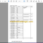
List of parts sent individually …………………………………………………………………………………… 23
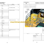
A. Assembly of Chassis …………………………………………………………………………………………. 33
A- 1. Installation of Left and Right Track Frames ………………………………………………….. 34
A- 2. Installation of Travel Piping ………………………………………………………………………… 37
A- 3. Installation of Travel Piping Covers …………………………………………………………….. 39
A- 4. Installation of Steps …………………………………………………………………………………… 41
A- 5. Filling Swing Circle with Grease …………………………………………………………………. 42
A- 6. Assembly of Upper Structure and Undercarriage ………………………………………….. 43
A- 7. Installation of Right Side Steps …………………………………………………………………… 45
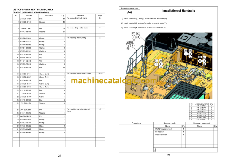
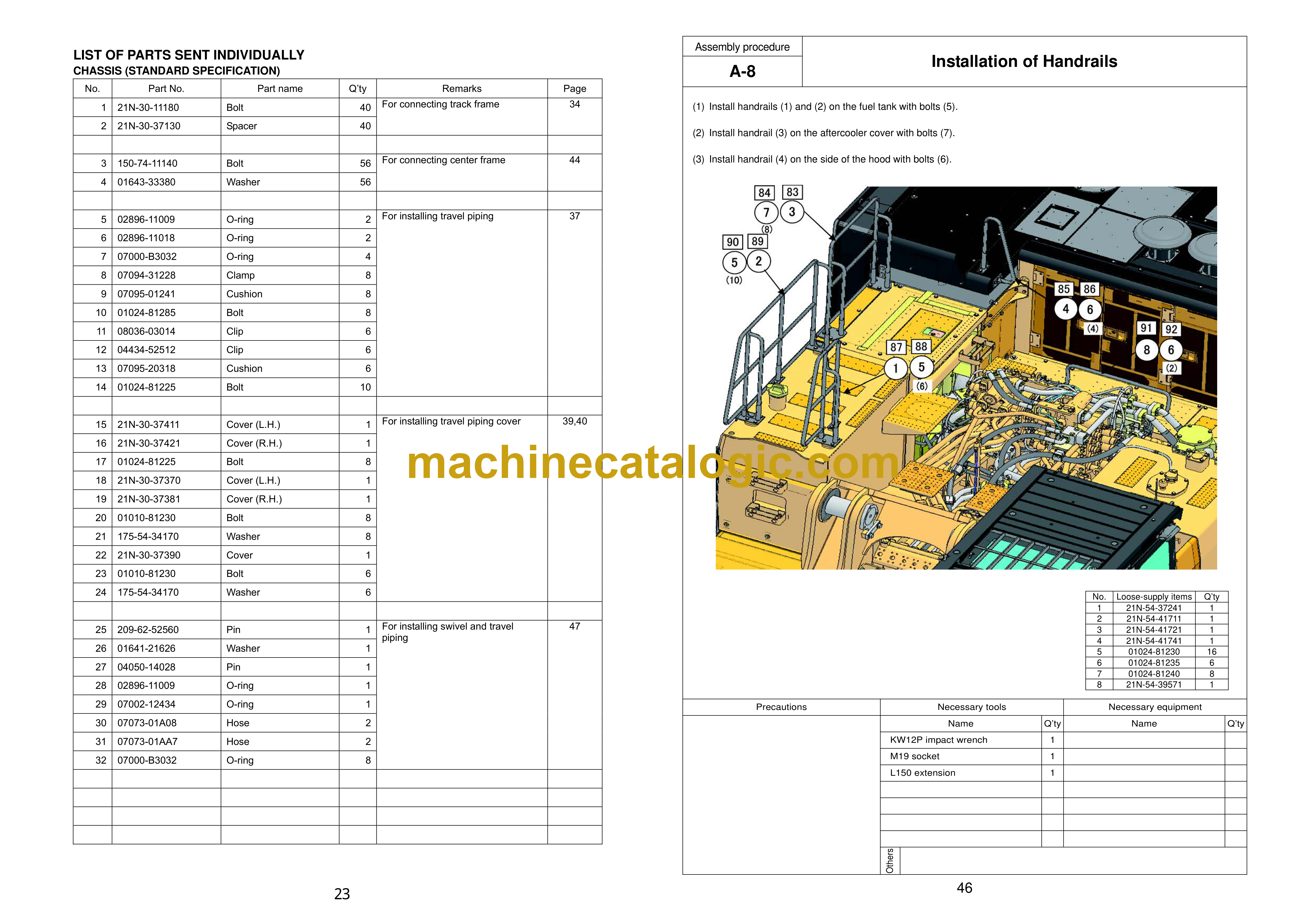
A- 8. Installation of Handrails …………………………………………………………………………….. 46
A- 9. Installation of Swivel Travel Piping ……………………………………………………………… 47
A-10. Sticking Sheet to Counterweight (EU specification) ………………………………………. 48
A-11. Installation of Cover board (To the Counterweight) ……………………………………….. 49
A-12. Installation of Counterweight …………………………………………………………………….. 50
A-13. Installation of Left Side Steps (Including handrails) ………………………………………. 51
A-14. Installation of Radiator Cover (Standard specification) ………………………………….. 54
A-15. Installation of Muffler Tail Pipe …………………………………………………………………… 59
A-16. Changing of Mounting Position of Step Light ……………………………………………….. 60
A-17. Installation of Handrail to the Cab ………………………………………………………………. 61
A-18. Installation of Left Rearview Mirror …………………………………………………………….. 62
A-19. Installation of Right Rearview Mirrors …………………………………………………………. 64
A-20. Installation of Rearview Mirror (On the Counterweight) (EU specification) ……….. 66
A-21. Preparation for Bleeding Air from Travel Motor …………………………………………….. 67
A-22. Procedure for Bleeding Air From Hydraulic Circuit ……………………………………….. 68
A-23. Permanent Tightening of Swing Circle Mounting Bolts ………………………………….. 69
A-24. Testing Track Shoe Tension ………………………………………………………………………. 70
A-25. Check Fuel, Coolant and Oil Levels …………………………………………………………… 73
A-26. Parts to be Touched up
after Field Assembly ……………………………………………….. 75
B. Assembling of Work Equipment of Backhoe …………………………………………………………. 77
B- 1. Installation of Arm Cylinder ………………………………………………………………………… 78
B- 2. Installation of Arm Cylinder Hoses ………………………………………………………………. 79
B- 3. Installation of Boom Cylinder Foot ………………………………………………………………. 80
B- 4. Installation of Boom Cylinder Hoses ……………………………………………………………. 81
B- 5. Installation of Boom Foot Dust Seal ……………………………………………………………. 82
B- 6. Installation of Boom Assembly ……………………………………………………………………. 83
B- 7. Installation of Boom Cylinder ……………………………………………………………………… 84
B- 8. Installation of Boom Hoses (Between machine and boom) …………………………….. 85
B- 9. Installation of Arm Assembly ………………………………………………………………………. 86
B-10. Installation of Bucket Cylinder Hoses between Boom and Bucket Cylinder ……… 88
B-11. Installation of Bucket Assembly …………………………………………………………………. 89
B-12. Clearance Standard for Installation of Work Equipment ………………………………… 92
B-13. Installation of Work Equipment Grease Piping …………………………………………….. 93
B-14. Procedure for Bleeding Air From Travel Motor …………………………………………….. 94
B-15. Bleeding Air from Swing Motor ………………………………………………………………….. 96
B-16. Bleeding Air from Cylinder ………………………………………………………………………… 97
B-17. Installation of Work Equipment Wiring ………………………………………………………… 98
B-18. Greasing after Assembling Work Equipment ……………………………………………….. 99
M. Procedure for Inspection and Maintenance after Completion of Assembly ……………….. 101
M- 1. Replacement of Return Filter (Standard Filter to Flushing Filter) …………………….. 102
M- 2. Relieving Remaining Pressure from Hydraulic Circuit ……………………………………. 105
M- 3. Installation of Flushing Tubes …………………………………………………………………….. 106
M- 4. Flushing of Hydraulic Circuit ………………………………………………………………………. 108
M- 5. Replacement of Pilot Filter (Flushing filter to Standard filter) …………………………… 109
C. Procedure for assembling work equipment of loading shovel ………………………………….. 111
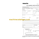
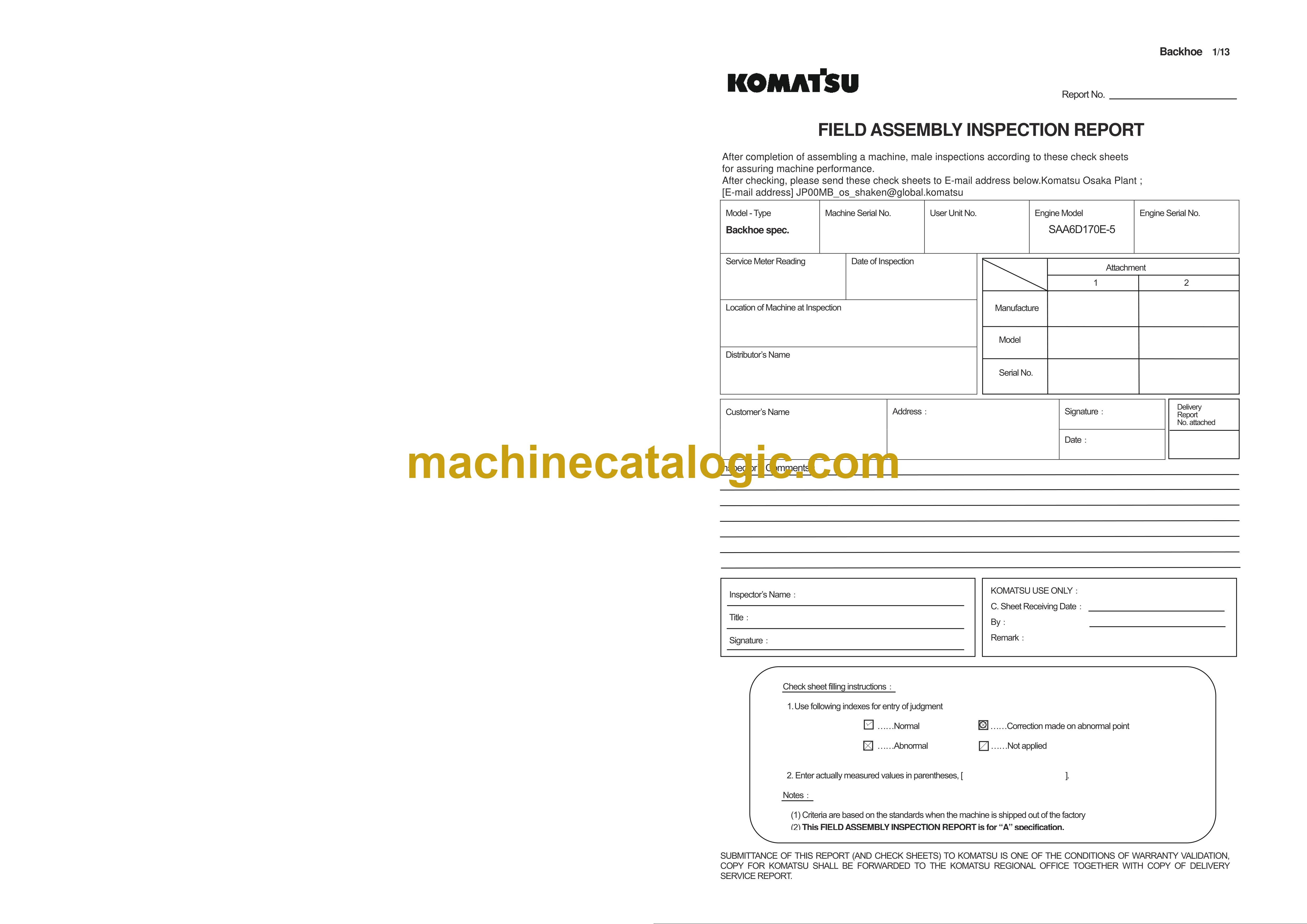
Field Assembly Inspection Report (Backhoe)
Field Assembly Inspection Report (Loading shovel)

