Format: PDF (Printable Document)
File Language: English
File Pages: 142
File Size: 12.80 MB (Speed Download Link)
Brand: Komatsu
Model: PC600-8 PC600LC-8
Book No: GEN00043-05
Serial No: 30001 and up
Type of Document: Shop Manual
$ 39
Specifications………………………………………………………………………………………………………. 1
Precautions for Field Assembly ……………………………………………………………………………… 2
Assembling Procedures, Applicable Equipment and Schedule …………………………………… 4
Kit Layout Diagram………………………………………………………………………………………………. 5
Transportation……………………………………………………………………………………………………… 6
List of Tools for Field Assembling…………………………………………………………………………… 11
Tightening Torque………………………………………………………………………………………………… 13
A. Assembly of Chassis ………………………………………………………………………………………… 19
A- 1. Installation of Left and Right Track Frames ………………………………………………….. 20
A- 2. Installation of Travel Pipe ………………………………………………………………………….. 24
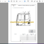
A- 3. Installation of Operator Cab’s Left Handrail………………………………………………….. 26
A- 4. Installation of Operator Cab’s Door Stopper and Striker ……………………………….. 27
A- 5. Installation of Rearview Mirror ……………………………………………………………………. 29
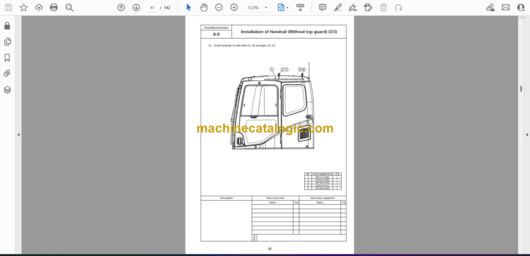
A- 6. Installation of Handrail ………………………………………………………………………………. 33
A- 7. Installation of Step ……………………………………………………………………………………. 36
A- 8. Installation of Left Side Step ………………………………………………………………………. 37
A- 9. Sticking Sheet to Counterweight…………………………………………………………………. 38
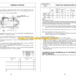
A-10. Installation of Counterweight ……………………………………………………………………… 39
A-11. Installation of Step Light ……………………………………………………………………………. 40
A-12. Installation of Travel Piping Cover………………………………………………………………. 42
A-13. Testing Track Shoe Tension………………………………………………………………………. 46
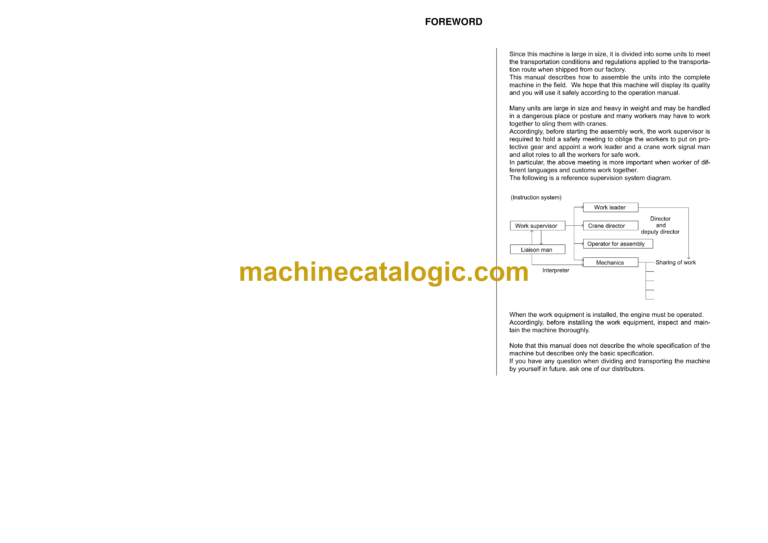
A-14. Check fuel, coolant and oil levels ……………………………………………………………….. 49
B. Assembling of Work Equipment …………………………………………………………………………. 53
B- 1. Assembly of Arm Cylinder …………………………………………………………………………. 54
B- 2. Connection of Arm Cylinder Hoses……………………………………………………………… 55
B- 3. Installation of Boom Cylinder ……………………………………………………………………… 56
B- 4. Installation of Boom Foot Dust Seal ……………………………………………………………. 57
B- 5. Assembly of Boom Assembly …………………………………………………………………….. 58
B- 6. Installation of Boom Cylinder Hoses……………………………………………………………. 59
B- 7. Installation of Hoses from Chassis Along Top of Boom………………………………….. 60
B- 8. Connection of Boom Cylinder Head ……………………………………………………………. 61
B- 9. Installation of Arm Assembly ……………………………………………………………………… 62
B-10. Installation of Bucket Cylinder Hoses between Boom and Bucket Cylinder………. 64
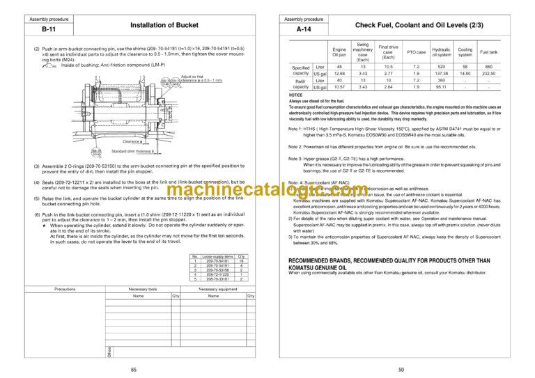
B-11. Installation of Bucket ………………………………………………………………………………… 65
B-12. Connection of Work Equipment Grease Piping …………………………………………….. 66
B-13. Connection of Work Equipment Wiring………………………………………………………… 67
B-14. Greasing after Assembling Work Equipment………………………………………………… 69
B-15. Bleeding Air from Work Equipment Circuit …………………………………………………… 70
B-16. Parts to be Touched up After Field Assembly ………………………………………………. 71
M. Procedure for Inspection and Maintenance after Completion of Assembly ………………. 73
M- 1. Inspection of Oil Level in Hydraulic Tank and Refill ………………………………………. 74
M- 2. Replacement of Return Filter (Standard Filter to Flushing Filter)…………………….. 76
M- 3. Flushing of Hydraulic Circuit ……………………………………………………………………… 79
M- 4. Error Code………………………………………………………………………………………………. 81
M- 5. Operating Method of Monitoring…………………………………………………………………. 86
D. Assembling of Counterweight Remover ……………………………………………………………. 91
D- 1. Sticking Sheet to Counterweight ………………………………………………………………. 92
D- 2. Adjustment of Shims for Counterweight…………………………………………………….. 93
D- 3. Greasing……………………………………………………………………………………………….. 98
D- 4. Installation of Counterweight Remover ……………………………………………………… 99
D- 5. Installation of Covers……………………………………………………………………………….
D- 6. Installation of Clamps………………………………………………………………………………
D- 7. Installation of Hoses………………………………………………………………………………..
1
104
D- 8. Bleeding Air from Counterweight Remover Circuit………………………………………. 105
D- 9. Installation of Counterweight……………………………………………………………………. 106
D-10. Check of Operation ………………………………………………………………………………… 108
Field Assembly Inspection Report (Backhoe)
