Format: PDF (Printable Document)
File Language: English
File Pages: 98
File Size: 5.36 MB (Speed Download Link)
Brand: Komatsu
Model: PC360LC-10
Book No: GEN00110-04
Serial No: 70001 and up
Type of Document: Shop Manual
$ 39
Specifications ………………………………………………………………………………………………………. 1
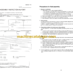
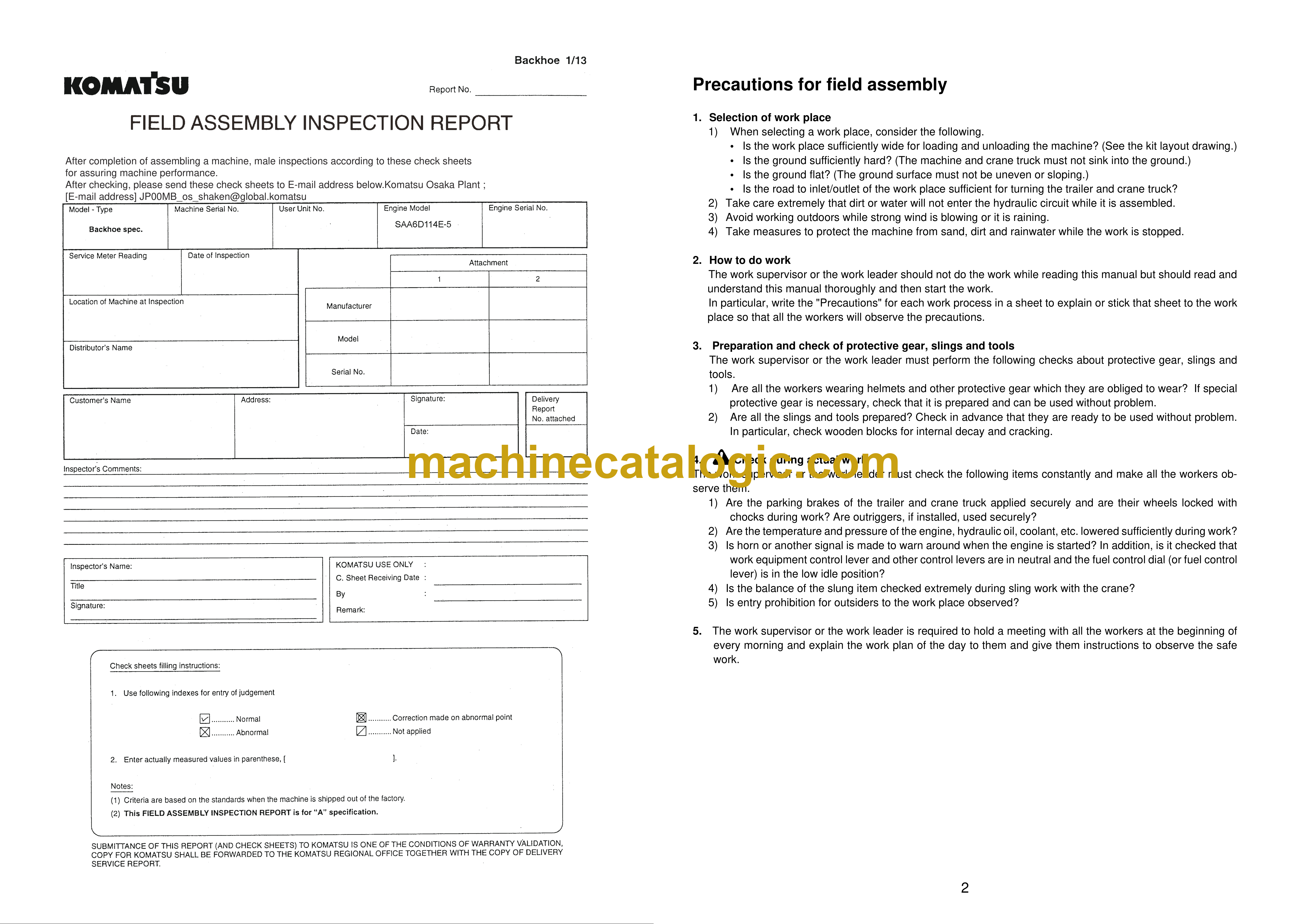
Precautions for field assembly ……………………………………………………………………………….. 2
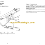
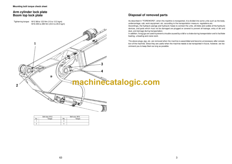
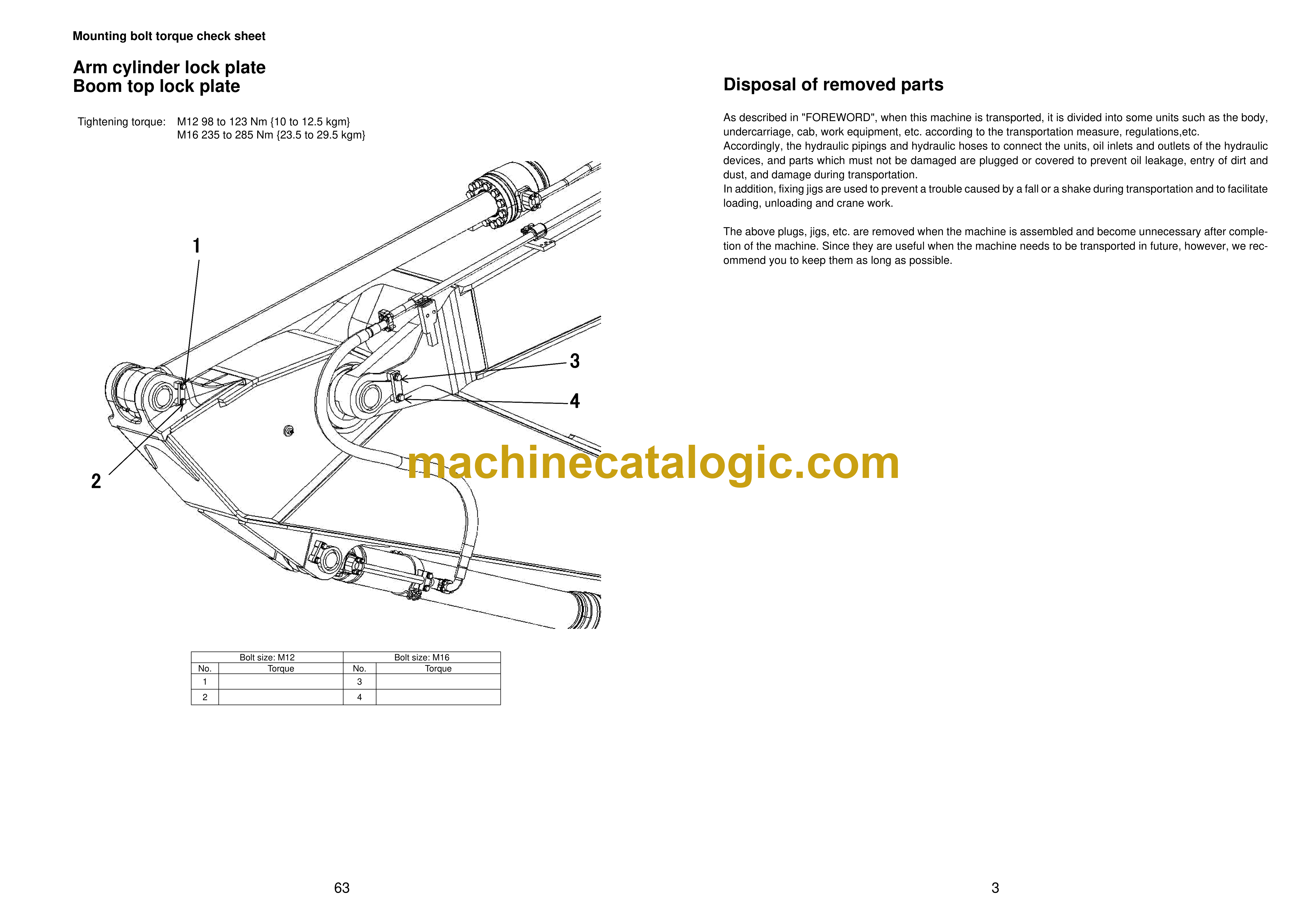
Disposal of removed parts……………………………………………………………………………………… 3
Assembling procedures, applicable equipment and schedule …………………………………….. 4
Flow of field assembly …………………………………………………………………………………………… 5
Kit layout diagram…………………………………………………………………………………………………. 6
Transportation ……………………………………………………………………………………………………… 7
Tool list for field assembly ……………………………………………………………………………………… 9
Tightening torque …………………………………………………………………………………………………. 10
Coating materials …………………………………………………………………………………………………. 15
Selection of wire ropes used for assembly……………………………………………………………….. 19
Selection of nylon slings used for assembly……………………………………………………………… 20
A. Assembly of chassis …………………………………………………………………………………………. 21
A- 1. Installation of handrail ……………………………………………………………………………….. 22
A- 2. Installation of mirror…………………………………………………………………………………… 24
B. Assembling of work equipment …………………………………………………………………………… 27
B- 1. Installation of arm assembly……………………………………………………………………….. 28
B- 2. Releasing remaining pressure in hydraulic circuit ………………………………………….. 30
B- 3. Installation of bucket cylinder hoses between boom and bucket cylinder ………….. 31
B- 4. Installation of bucket………………………………………………………………………………….. 32
B- 5. Greasing after completion of work equipment……………………………………………….. 35
B- 6. Bleeding air from work equipment circuit ……………………………………………………… 36
C. Increasing and decreasing of track frame gauge, assembling of counterweight………… 37
C- 1. Adjustment of track tension ……………………………………………………………………….. 38
C- 2. Sticking sheet to counterweight ………………………………………………………………….. 41
C- 3. Installation of camera………………………………………………………………………………… 42
C- 4. Installation of counterweight……………………………………………………………………….. 48
M. Procedure for inspection and maintenance after completion of assembly ………………… 51
M- 1. Replacement of return filter (Standard filter to flushing filter) ………………………….. 52
M- 2. Flushing of hydraulic circuit ……………………………………………………………………….. 53
M- 3. Replacement of return filter (Standard filter to flushing filter) ………………………….. 55
M- 4. Check of oil/coolant level at each part …………………………………………………………. 57
M- 5. Inspection of oil level in hydraulic tank and refill……………………………………………. 59
M- 6. Parts to be touched up after field assembly………………………………………………….. 61
M- 7. Error code……………………………………………………………………………………………….. 62
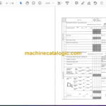
Mounting bolt torque check sheet
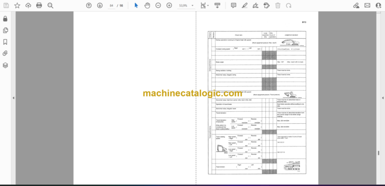
Field assembly inspection report (Backhoe)
