On a 325 mini excavator, this is the book you grab when the machine stops pulling, a cylinder starts leaking, or an electrical gremlin kills your boom or travel. Around my shop, the service manual is what I open when I'm past simple filters and fuses and I actually need specs, test ports, and teardown order. If you're trying to keep downtime down and avoid guessing on a used 325, this is the kind of manual you want.
What this manual helps you do
- Trace hydraulic issues on the 325, then pressure-test circuits and confirm if a pump, valve, or cylinder is at fault
- Check and adjust the engine and hydrostatic systems using the correct test points and adjustment procedures
- Follow step-by-step removal and installation for major components like drive motors, cylinders, swing gear, and boom/stick assemblies
- Diagnose electrical problems using wiring diagrams so you can track dead circuits, bad switches, or sensor faults
- Rebuild and replace wear parts with the right disassembly order, inspection points, and reassembly specs
Who this is for
This is for anyone running or fixing a Bobcat 325 excavator in the serial range 232311001-232399999, whether you're a small contractor, owner-operator, or shop mechanic. If you just need basic controls, daily checks, or safety info, you want the operator's handbook instead, not this service manual.
FAQ
Q: Is this a searchable PDF, and can I read the wiring diagrams clearly?
A: Yes, it's a PDF you can search by keyword, and wiring diagrams are sized so you can zoom in to follow individual wires.
Q: How do I know if it fits my exact 325?
A: Check your serial number plate. If it falls between 232311001 and 232399999, this is the correct manual.
Q: Is this the right document if I'm planning a pump or drive motor rebuild?
A: Yes, this is the workshop-level service manual, meant for full repair work, not just basic maintenance.
Bottom line: If your 325's serial number is in that range and you're doing your own repairs, this is the right manual. If the serial doesn't match, don't buy it.
📘 Show Index
Table of Contents:
- MAINTENANCE SAFETY
- ALPHABETICAL INDEX
- CONTENTS
- FOREWORD
- SAFETY INSTRUCTIONS
- SERIAL NUMBER LOCATIONS
- Bobcat Excavator Serial Number
- Engine Serial Number
- DELIVERY REPORT
- BOBCAT EXCAVATOR IDENTIFICATION
- SAFETY AND MAINTENANCE
- LIFTING AND BLOCKING THE EXCAVATOR
- SWING LOCK
- LIFTING THE EXCAVATOR
- OPERATOR CAB (ROPS / TOPS) (IF EQUIPPED)
- Emergency Exit
- Cab Door
- Front Window
- TRANSPORTING THE EXCAVATOR
- TAILGATE
- Opening And Closing The Tailgate (Early Models)
- Adjusting The Bumper (Early Models)
- Adjusting The Tailgate Latch (Early Models)
- Opening And Closing The Tailgate (Later Models)
- Adjusting The Tailgate Latch (Later Models)
- Adjusting The Bumper (Later Models)
- SERVICE SCHEDULE
- AIR CLEANER SERVICE
- Daily Check
- Replacing The Filters
- HEATER AIR FILTERS (WITH CAB OPTION ONLY)
- Recirculation Filter
- Fresh Air Filter
- ENGINE COOLING SYSTEM
- Cleaning The Cooling System
- Checking The Coolant Level
- Replacing The Coolant
- FUEL SYSTEM
- Fuel Specification
- Filling The Fuel Tank
- Removing Water From The Fuel Filter
- Fuel Filter
- Removing Air From The Fuel System
- Draining The Fuel Tank
- ENGINE LUBRICATION SYSTEM
- Checking Engine Oil
- Replacing Oil And Filter
- HYDRAULIC SYSTEM
- Checking And Adding Fluid
- Replacing the Hydraulic Filter
- Replacing the Case Drain Filter
- Replacing the Hydraulic Fluid
- Diagnostic Couplers
- LUBRICATING THE EXCAVATOR
- TRAVEL MOTOR
- Checking Oil Level
- Draining The Travel Motor
- SPARK ARRESTOR MUFFLER (IF EQUIPPED)
- Cleaning The Spark Arrestor Muffler
- HYDRAULIC SYSTEM
- HYDRAULIC/HYDROSTATIC SCHEMATICS
- HYDRAULIC SYSTEM INFORMATION
- Glossary Of Hydraulic / Hydrostatic Symbols
- Troubleshooting Chart
- BOOM CYLINDER
- Checking The Boom Cylinder
- Removal And Installation
- Parts Identification
- Disassembly
- Assembly
- ARM CYLINDER
- Checking The Arm Cylinder
- Removal And Installation
- Parts Identification
- Disassembly
- Assembly
- BOOM OFFSET CYLINDER
- Checking The Boom Offset Cylinder
- Removal And Installation
- Parts Identification
- Disassembly
- Assembly
- BUCKET CYLINDER
- Checking The Bucket Cylinder
- Removal And Installation
- Parts Identification
- Disassembly
- Assembly
- BLADE CYLINDER
- Checking The Blade Cylinder
- Removal And Installation
- Parts Identification
- Disassembly
- Assembly
- MAIN RELIEF VALVES
- Testing And Adjusting The Main Relief Valves (S/N 232312386 & Below, 232412117 & Below, 232412128 And 232412129)
- Testing And Adjusting The Main Relief Valves (S/N 232312387 & Above, 232412118-232412127 And 232412130 & Above)
- PORT RELIEF VALVES
- Testing And Adjusting Port Relief Valve Pressure (S/ N 232312386 & Below And 232412117 & Below, 232412128 And 232412129)
- Testing Port Relief Valve Pressure (S/N 232312387 & Above And 232412118-232412127 And 232412130 & Above)
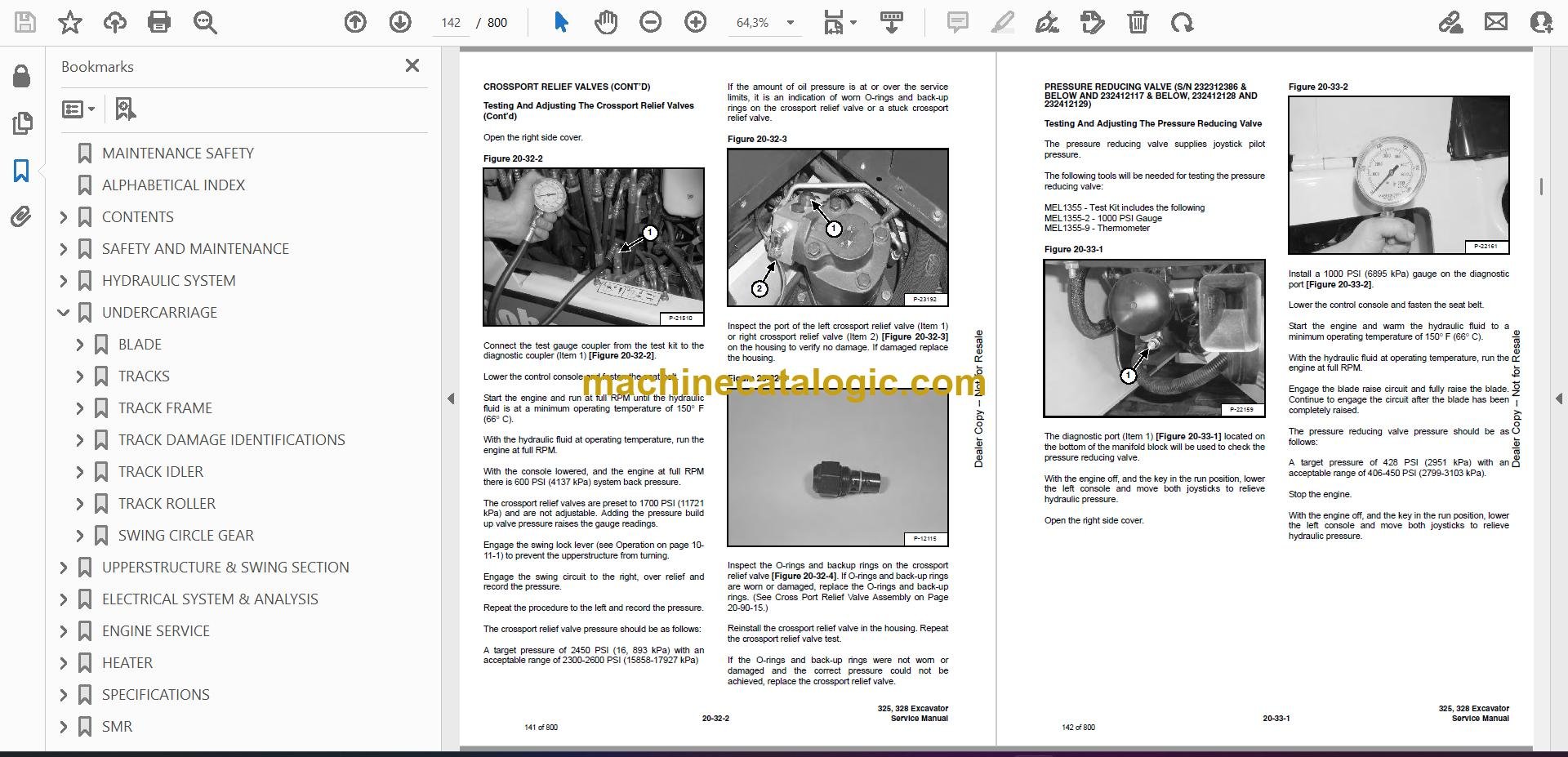
- CROSSPORT RELIEF VALVES
- Testing And Adjusting The Crossport Relief Valves
- SYSTEM PRESSURES AT GAUGE PORT SPECIFICATIONS
- PRESSURE REDUCING VALVE (S/N 232312386 & BELOW AND 232412117 & BELOW, 232412128 AND 232412129)
- Testing And Adjusting The Pressure Reducing Valve
- PRESSURE REDUCING VALVE (S/N 232312387 & ABOVE AND 232412118-232412127 AND 232412130 & ABOVE)
- Testing And Adjusting The Pressure Reducing Valve
- HYDRAULIC CONTROL VALVE (S/N 232312386 & BELOW, 232412117 & BELOW, 232412128 AND 232412129)
- Description
- Removal And Installation
- Control Valve Identification
- Disassembly
- Right Travel Valve Section Disassembly And Assembly
- Boom Offset Valve Section Disassembly And Assembly
- Boom Valve Section Disassembly And Assembly
- Left Travel Valve Section Disassembly And Assembly
- Arm Valve Section Disassembly And Assembly
- Bucket Valve Section Disassembly And Assembly
- Auxiliary Valve Section Disassembly And Assembly
- Boost Valve Section Disassembly And Assembly
- Blade Valve Section Disassembly And Assembly
- Swing Valve Section Disassembly And Assembly
- Assembly
- HYDRAULIC CONTROL VALVE (S/N 232312387 & ABOVE, 232412118-232412127 AND 232412130 & ABOVE)
- Description
- Removal And Installation
- Control Valve Identification
- Disassembly
- Right Travel Valve Section Disassembly And Assembly
- Boom Offset Valve Section Disassembly And Assembly
- Boom Valve Section Disassembly And Assembly
- Left Travel Valve Section Disassembly And Assembly
- Arm Valve Section Disassembly And Assembly
- Bucket Valve Section Disassembly And Assembly
- Auxiliary Valve Section Disassembly And Assembly
- Boost Valve Section Disassembly And Assembly
- Blade Valve Section Disassembly And Assembly
- Swing Valve Section Disassembly And Assembly
- Assembly
- HYDRAULIC PUMP
- Description
- Torque Adjustment
- Testing The Piston Pump
- Testing The Gear Pump
- Testing The Auxiliary Hydraulic Flow
- Removal And Installation
- Coupler Removal And Installation
- Gear Pump Parts Identification
- Piston Pump Parts Identification
- Disassembly
- Gear Pump Disassembly
- Gear Pump Assembly
- Piston Pump Disassembly
- Piston Pump Assembly
- Assembly
- MANIFOLD ASSEMBLY/ACCUMULATOR (S/N 232311950 & BELOW AND 232411763 & BELOW)
- Manifold Description
- Removal And Installation
- MANIFOLD ASSEMBLY (S/N 232311950 & BELOW AND 232411763 & BELOW)
- Parts Identification
- Disassembly
- Assembly
- MANIFOLD ASSEMBLY/ACCUMULATOR (S/N 232311951 & ABOVE AND 232411764 & ABOVE)
- Manifold Description
- Removal And Installation
- MANIFOLD ASSEMBLY (S/N 232311951 & ABOVE AND 232411764 & ABOVE)
- Parts Identification
- Disassembly
- Assembly
- TRAVEL MOTOR
- Removal And Installation
- Parts Identification
- Disassembly
- Assembly
- SWIVEL JOINT
- Removal And Installation (With The Upperstructure Removed)
- Removal And Installation (Through Bottom Access Cover)
- Parts Identification
- Description
- Disassembly
- Assembly
- SWING MOTOR
- Removal And Installation
- Parts Identification
- Disassembly
- Assembly
- Cross Port Relief Valve Parts Identification
- Cross Port Relief Valve Disassembly
- Cross Port Relief Valve Assembly
- SWING MOTOR DRIVE CARRIER
- Removal And Installation
- Parts Identification
- Disassembly
- Assembly
- CONTROL PATTERN SELECTOR VALVE
- Removal And Installation
- Parts Identification
- Disassembly
- Assembly
- RIGHT CONTROL LEVER (JOYSTICK) (S/N 232312386 & BELOW, 232412117 & BELOW, 232412128 AND 232412129)
- Testing
- Handle Removal And Installation
- Joystick Assembly, Removal And Installation
- Parts Identification
- Disassembly
- LEFT CONTROL LEVER (JOYSTICK) (S/N 232312386 & BELOW, 232412117 & BELOW, 232412128 AND 232412129)
- Testing
- Handle Removal And Installation
- Joystick Assembly Removal And Installation
- Parts Identification
- Disassembly
- LEFT CONTROL LEVER (JOYSTICK) (S/N 232312387 & ABOVE, 232412118-232412127 AND 232412130 & ABOVE)
- Testing
- Handle Removal And Installation
- Joystick Assembly Removal And Installation
- Parts Identification
- Disassembly
- Assembly
- RIGHT CONTROL LEVER (JOYSTICK) (S/N 232312387 & ABOVE, 232412118-232412127 AND 232412130 & ABOVE)
- Testing
- Handle Removal And Installation
- Joystick Assembly Removal And Installation
- Parts Identification
- Disassembly
- Assembly
- HYDRAULIC FILTER
- HYDRAULIC RESERVOIR
- OIL COOLER
- DIRECT TO TANK VALVE
- Removal And Installation
- Disassembly And Assembly
- BUILD UP VALVE
- Description
- Removal And Installation
- Disassembly And Assembly
- CASE DRAIN FILTER
- UNDERCARRIAGE
- BLADE
- TRACKS
- Track Lug Height
- Adjustment
- Rubber Track Removal And Installation
- Steel Track Removal And Installation
- TRACK FRAME
- Disassembly And Assembly
- Recoil Spring Disassembly And Assembly
- TRACK DAMAGE IDENTIFICATIONS
- Cutting Of Steel Cords
- Abrasion Of Embedded Metals
- Separation Of Embedded Metals
- Separation Of Embedded Metals Due To Corrosion
- Cuts On The Lug Side Rubber
- Cracks On The Lug Side Rubber Due To Fatigue
- Lug Abrasion
- Cracks And Cuts On The Lug Side Rubber
- Abrasion Of The Track Roller Side
- Cuts On The Edges Of Track Roller Side
- TRACK IDLER
- Parts Identification (S/N 232311036 & Below And 232411019 & Below)
- Disassembly (S/N 232311036 & Below And 232411019 & Below)
- Assembly (S/N 232311036 & Below And 232411019 & Below)
- Parts Identification (S/N 232311037 & Above And 232411020 & Above)
- Disassembly (S/N 232311037 & Above And 232411020 & Above)
- Assembly (S/N 232311037 & Above And 232411020 & Above)
- TRACK ROLLER
- Parts Identification (S/N 232311036 & Below And 232411019 & Below)
- Disassembly (S/N 232311036 & Below And 232411019 & Below)
- Assembly (S/N 232311036 & Below And 232411019 & Below)
- Parts Identification (S/N 232311037 & Above And 232411020 & Above)
- Disassembly (S/N 232311037 & Above And 232411020 & Above)
- Assembly (S/N 232311037 & Above And 232411020 & Above)
- SWING CIRCLE GEAR
- Removal And Installation
- Swing Bearing Removal
- Swing Bearing Installation
- Alignment Pins (Not Threaded)
- UPPERSTRUCTURE & SWING SECTION
- UPPERSTRUCTURE
- Removal And Installation
- Swing Bearing Removal
- Swing Bearing Installation
- Alignment Pins (Not Threaded)
- ROPS CANOPY
- CAB
- Removal And Installation
- Door Removal And Installation
- Front Window Removal And Installation
- Lower Front Window Removal And Installation
- Right Side Rear Sliding Window Removal And Installation
- Right Side Front Sliding Window Removal And Installation
- Right Side Panel And Window Assembly Removal And Installation
- Door, Left Side, Rear And Upper Front Window Removal And Installation
- STANDARD SEAT AND SEAT MOUNT
- SUSPENSION SEAT AND SEAT MOUNT
- RIGHT CONSOLE
- Console Cover Removal And Installation
- Console Base Removal And Installation
- LEFT CONSOLE
- Lower Console Cover Removal And Installation
- Upper Console Cover Removal And Installation
- Compression Spring Removal And Installation
- Lock Lever Removal And Installation
- Upper Console Removal And Installation
- Console Switch Removal And Installation
- Disassembly And Assembly
- Console Base Removal And Installation
- ENGINE SPEED CONTROL
- BLADE CONTROL
- Lever Removal And Installation
- Linkage Removal And Installation
- Linkage Bar Removal And Installation
- Lower Linkage Removal And Installation
- RIGHT PEDAL AND LINKAGE
- Pedal Removal And Installation
- Right Pedal Disassembly And Assembly
- Linkage Removal And Installation
- Adjustment
- TRAVEL CONTROLS
- Removal And Installation
- Disassembly And Assembly
- Adjustment
- FLOOR MAT AND FLOOR PANELS
- FUEL TANK
- HORN
- SWING FRAME
- Boom Swing Bracket Removal And Installation
- Boom Swing Bracket Hose Installation
- Bushing Removal
- Bushing Installation
- BOOM
- Removal And Installation
- Boom Bushing Removal And Installation
- ARM
- Removal And Installation
- Arm To Boom Bushing Removal And Installation
- Arm To Bucket And Bucket Link Bushing Removal And Installation
- BUCKET
- Bucket Teeth Removal And Installation
- Bucket Side Cutting Edge Removal And Installation
- TAILGATE
- Removal And Installation
- Release Rod Removal And Installation
- Latch Removal And Installation
- Release Rod Removal And Installation (Early Models)
- Latch Removal And Installation (Early Models)
- Latch Removal And Installation (Later Models)
- X-CHANGE™
- Removal And Installation
- Disassembly
- Assembly
- RIGHT SIDE COVER
- ELECTRICAL SYSTEM & ANALYSIS
- ELECTRICAL SCHEMATIC
- ELECTRICAL SYSTEM INFORMATION
- Glossary Of Electrical Symbols
- Troubleshooting Chart
- Description
- Fuse Location
- BATTERY
- Servicing
- Removal And Installation
- Using A Booster Battery (Jump Starting)
- ALTERNATOR
- Adjusting The Alternator Belt
- Description
- Tests
- Alternator Output Test
- Full Field Test
- Alternator Regulator Test
- Removal And Installation
- Disassembly And Assembly
- STARTER
- Removal And Installation
- Parts Identification
- Disassembly
- Inspection And Repair
- Assembly
- LIGHTS
- Removal And Installation
- Disassembly And Assembly
- FUEL LEVEL SENDER
- Removal And Installation
- Testing
- DIAGNOSTICS SERVICE CODE
- ENGINE SERVICE
- TROUBLESHOOTING
- MUFFLER
- AIR CLEANER
- RADIATOR
- ENGINE COMPONENTS AND TESTING
- Valve Clearance Adjustment
- Engine Compression Checking
- Fuel Shutoff Solenoid Adjustment
- Fuel Shutoff Solenoid Removal And Installation
- Fuel Injection Pump Check
- Fuel Injection Pump Removal And Installation
- Fuel Injection Pump Timing
- Fuel Injector Nozzles Removal And Installation
- Checking The Injector Nozzle
- Glow Plug Removal And Installation
- Glow Plug Checking
- ENGINE
- ENGINE FLYWHEEL
- Removal And Installation
- Flywheel Ring Gear
- RECONDITIONING THE ENGINE
- Cylinder Head Removal And Installation
- Cylinder Head Disassembly And Assembly
- Cylinder Head Servicing
- Cylinder Head Top Clearance
- Valve Guide, Checking
- Reconditioning The Valve And Valve Seat
- Valve Spring
- Rocker Arm And Shaft Checking
- Timing Gearcase Cover Removal And Installation
- Idler Gear And Camshaft Removal And Installation
- Idler Gear And Shaft Servicing
- Timing Gears Checking Backlash
- Fuel Camshaft Removal And Installation
- Fuel Camshaft Governor
- Crankshaft Gear Removal And Installation
- Oil Pump Removal And Installation
- Oil Pump Service
- Engine Oil Pressure, Checking
- Relief Valve
- Piston And Connecting Rod Removal And Installation
- Piston And Connecting Rod Servicing
- Connecting Rod Alignment
- Crankshaft And Bearings Removal And Installation
- Crankshaft And Bearings, Servicing
- Cylinder Bore, Checking
- Water Pump Removal And Installation
- Water Pump Disassembly And Assembly
- Fan Removal And Installation
- HEATER
- HEATER UNIT
- Removal And Installation
- Disassembly And Assembly
- HEATER COIL
- HEATER FAN
- Removal And Installation
- Disassembly And Assembly
- Resistor Removal And Installation
- Wire Connector Removal And Installation
- HEATER VALVE
- SPECIFICATIONS
- HYDRAULIC EXCAVATOR SPECIFICATIONS (325)
- Machine Dimensions
- Lifting Capacity
- Weights
- Controls
- Engine
- Electrical
- Hydraulic System
- Swing System
- Hydraulic Cylinders
- Drive System
- Brakes
- Undercarriage
- STD Track
- Capacities
- Digging Force
- HYDRAULIC EXCAVATOR SPECIFICATIONS (325 W/LONG ARM KIT & 328)
- Machine Dimensions
- Lifting Capacities
- Weights
- Controls
- Engine
- Electrical
- Hydraulic System
- Swing System
- Hydraulic Cylinders
- Drive System
- Brakes
- Undercarriage
- STD Track
- Capacities
- Digging Force
- ENGINE SPECIFICATIONS
- Fuel Injection Nozzles
- Fuel Injection Pump
- Cylinder Head
- Valves
- Valve Springs
- Valve Timing
- Rocker Arms
- Camshaft
- Tappet
- Cylinders
- Piston Rings
- Pistons
- Connecting Rods
- Oil Pump
- Crankshaft
- Thermostat
- Timing Gear
- Engine Bolt Torque
- Crankshaft Re-Grind Data
- TORQUE SPECIFICATIONS
- Torque For General SAE Bolts
- Torque For General Metric Bolts
- HYDRAULIC CONNECTION SPECIFICATIONS
- O-Ring Face Seal Connection
- Straight Thread O-Ring Fitting
- Tubelines And Hoses
- Flare Fitting
- O-Ring Flare Fitting
- Port Seal Fitting
- HYDRAULIC FLUID SPECIFICATIONS
- FUEL, COOLANT AND LUBRICANTS
- CONVERSIONS
- Decimal And Millimeter Equivalents
- U.S. To Metric Conversion
- SMR
- 325/328-1
- 325/328-2
- 325/328-3
- 325/328-4
Bobcat Software
Bobcat PDF Manuals


