A 331 is a handy little digger for trenching, footings, water lines, and all the ugly jobs you can't get a skid-steer into. When something quits swinging, tracks quit pulling, or a cylinder starts leaking, this is when you reach for the service manual. In my experience, you want this book when the weekend is your repair window and you'd rather fix it in the yard than haul it to town. That's when the right manual saves your bacon.
What this manual helps you do
- Diagnose weak or no movement in the boom, arm, bucket, or blade hydraulics
- Trace and test electrical circuits using wiring diagrams when you've got a no-start or dead function
- Check hydrostatic drive issues like one track pulling weak or not moving at all
- Follow teardown and reassembly steps for cylinders, pumps, motors, and major components
- Set and verify adjustments after repairs so pressures, linkages, and controls are back in spec
Who this is for
This manual is for Bobcat 331 excavator owners, small contractors, farm and ranch shops, and field techs who actually turn wrenches. If you're just looking for how to run the machine or basic maintenance intervals, you want the operator's handbook instead, not this service manual.
FAQ
Q: Is this a searchable PDF and are the wiring diagrams readable?
A: Yes, these manuals are usually supplied as a searchable PDF with zoomable wiring diagrams you can read on a laptop or tablet.
Q: Does this cover my exact 331 machine?
A: It matches Bobcat 331 excavators in the serial number range 232511001 through 232599999. If your plate falls in that range, you're good.
Q: Is this the right document if I'm rebuilding or troubleshooting?
A: Yes, this is the workshop-level service manual, not a parts book or operator's manual, so it's the one you want for real repair work.
Bottom line, if your 331's serial number lands between 232511001 and 232599999 and you're doing your own repairs, this is the manual you need.
📘 Show Index
Table of Contents:
- MAINTENANCE SAFETY
- ALPHABETICAL INDEX
- CONTENTS
- FOREWORD
- SAFETY INSTRUCTIONS
- SERIAL NUMBER LOCATIONS
- Bobcat Excavator Serial Number
- Engine Serial Number
- DELIVERY REPORT
- BOBCAT EXCAVATOR IDENTIFICATION
- SAFETY AND MAINTENANCE
- LIFTING AND BLOCKING THE EXCAVATOR
- SWING LOCK
- LIFTING THE EXCAVATOR
- OPERATOR CAB (ROPS/TOPS) (IF EQUIPPED)
- Emergency Exit
- Cab Door
- Front Window
- TRANSPORTING THE EXCAVATOR
- TAILGATE
- Opening And Closing The Tailgate (Early Models)
- Adjusting The Bumper
- Adjusting The Tailgate Latch (Early Models)
- Opening And Closing The Tailgate (Later Models)
- Adjusting The Tailgate Latch (Later Models)
- SERVICE SCHEDULE
- AIR CLEANER SERVICE
- Daily Check
- Replacing The Filters
- HEATER AIR FILTERS (WITH CAB OPTION ONLY)
- Recirculation Filter
- Fresh Air Filter
- ENGINE COOLING SYSTEM
- Cleaning The Cooling System
- Checking The Coolant Level
- Replacing The Coolant
- FUEL SYSTEM
- Fuel Specification
- Filling The Fuel Tank
- Removing Water From The Fuel Filter
- Replacing The Fuel Filter
- Removing Air From The Fuel System
- Draining The Fuel Tank
- ENGINE LUBRICATION SYSTEM
- HYDRAULIC SYSTEM
- Checking And Adding Fluid
- Replacing The Hydraulic Filter
- Replacing The Case Drain Filter
- Replacing The Hydraulic Fluid
- Diagnostic Couplers
- LUBRICATING THE EXCAVATOR
- TRAVEL MOTOR
- Checking Oil Level
- Draining The Travel Motor
- SPARK ARRESTOR MUFFLER
- Cleaning The Spark Arrestor Muffler
- Continued On Next Page
- Continued On Next Page
- Continued On Next Page
- Continued On Next Page
- Continued On Next Page
- HYDRAULIC SYSTEM
- HYDRAULIC/HYDROSTATIC SCHEMATICS
- HYDRAULIC SYSTEM INFORMATION
- Glossary Of Hydraulic/Hydrostatic Symbols For Excavators
- Troubleshooting The Hydraulic Circuit
- Troubleshooting The Cylinder Circuit
- Troubleshooting The Swing (Slew) Circuit
- Troubleshooting The Travel Circuit
- BOOM CYLINDER
- Checking The Boom Cylinder
- Removal And Installation
- Parts Identification
- Disassembly
- Assembly
- ARM CYLINDER
- Checking The Arm Cylinder
- Removal And Installation
- Parts Identification
- Disassembly
- Assembly
- BOOM OFFSET CYLINDER
- Checking The Boom Offset Cylinder
- Removal And Installation
- Parts Identification
- Disassembly
- Assembly
- BUCKET CYLINDER
- Checking The Bucket Cylinder
- Removal And Installation (Standard And Long Arm)
- Removal And Installation (Extendible Arm)
- Parts Identification
- Disassembly
- Assembly
- BLADE CYLINDER
- Checking The Blade Cylinder
- Removal And Installation
- Parts Identification
- Disassembly
- Assembly
- EXTENDIBLE ARM CYLINDER
- Removal And Installation
- Parts Identification
- MAIN RELIEF VALVES
- Testing And Adjusting The Main Relief Valves (S/N 232512782 & Below, 232711433 & Below And 232612157 & Below)
- System Pressures At Gauge Port Specifications (S/N 232512782 & Below, 232711433 & Below And 232612157 & Below)
- Testing And Adjusting The Main Relief Valves (S/N 232512783 & Above, 232711434 & Above And 232612158 & Above)
- System Pressures At Gauge Port Specifications (S/N 232512783 & Above, 232711434 & Above And 232612158 & Above)
- PORT RELIEF VALVES
- Testing And Adjusting Port Relief Valve Pressure (S/ N 232512782 & Below, 232711433 & Below And 232612157 & Below)
- Testing And Adjusting Port Relief Valve Pressure (S/ N 232512783 & Above, 232711434 & Above And 232612158 & Above)
- CROSSPORT RELIEF VALVES
- Testing The Crossport Relief Valves
- System Pressures At Gauge Port Specifications
- PRESSURE REDUCING VALVE
- Testing And Adjusting The Pressure Reducing Valve (S/N 232512782 & Below, 232711433 & Below And 232612157 & Below)
- Testing And Adjusting The Pressure Reducing Valve (S/N 232512783 & Above, 232711434 & Above And 232612158 & Above)
- HYDRAULIC CONTROL VALVE (S/N 232512782 & BELOW, 232711433 & BELOW AND 232612157 & BELOW)
- Description
- Removal And Installation
- Control Valve Identification
- Disassembly
- Right Travel Valve Section Disassembly And Assembly
- Boom Offset Valve Section Disassembly And Assembly
- Boom Valve Section Disassembly And Assembly
- Left Travel Valve Section Disassembly And Assembly
- Arm Valve Section Disassembly And Assembly
- Bucket Valve Section Disassembly And Assembly
- Auxiliary Valve Section Disassembly And Assembly
- Boost Valve Section Disassembly And Assembly
- Blade Valve Section Disassembly And Assembly
- Swing Valve Section Disassembly And Assembly
- Assembly
- HYDRAULIC CONTROL VALVE (S/N 232512783 & ABOVE, 232711434 & ABOVE AND 232612158 & ABOVE)
- Description
- Removal And Installation
- Control Valve Identification
- Disassembly
- Right Travel Valve Section Disassembly And Assembly
- Boom Offset Valve Section Disassembly And Assembly
- Boom Valve Section Disassembly And Assembly
- Left Travel Valve Section Disassembly And Assembly
- Arm Valve Section Disassembly And Assembly
- Bucket Valve Section Disassembly And Assembly
- Auxiliary Valve Section Disassembly And Assembly
- Boost Valve Section Disassembly And Assembly
- Blade Valve Section Disassembly And Assembly
- Swing Valve Section Disassembly And Assembly
- Assembly
- HYDRAULIC PUMP
- Description
- Torque Adjustment
- Testing The Piston Pump
- Testing The Gear Pump
- Testing Auxiliary Hydraulic Flow
- Removal And Installation
- Coupler Removal And Installation
- Parts Identification
- Piston Pump Parts Identification
- Disassembly
- Gear Pump Disassembly
- Gear Pump Assembly
- Piston Pump Disassembly
- Piston Pump Assembly
- Assembly
- MANIFOLD ASSEMBLY/ACCUMULATOR (S/N 232512162 & BELOW, 232611711 & BELOW AND 232711316 & BELOW)
- Manifold Description
- Removal And Installation
- MANIFOLD ASSEMBLY (S/N 232512162 & BELOW, 232611711 & BELOW AND 232711316 & BELOW)
- Parts Identification
- Disassembly
- Assembly
- MANIFOLD ASSEMBLY/ ACCUMULATOR (S/N 232512163 & ABOVE, 232611712 & ABOVE AND 232711317 & ABOVE)
- Manifold Description
- Removal And Installation
- MANIFOLD ASSEMBLY (S/N 232512163 & ABOVE, 232611712 & ABOVE AND 232711317 & ABOVE)
- Parts Identification
- Disassembly
- Assembly
- TRAVEL MOTOR
- Removal And Installation
- Parts Identification
- Disassembly
- Assembly
- SWIVEL JOINT
- Removal And Installation
- Parts Identification
- Description
- Disassembly
- Assembly
- SWING MOTOR
- Removal And Installation
- Parts Identification
- Disassembly
- Assembly
- Cross Port Relief Valve Parts Identification
- Cross Port Relief Valve Disassembly
- Cross Port Relief Valve Assembly
- SWING MOTOR DRIVE CARRIER
- Removal And Installation
- Parts Identification
- Disassembly
- Assembly
- CONTROL PATTERN SELECTOR VALVE
- Removal And Installation
- Parts Identification
- Disassembly
- Assembly
- RIGHT CONTROL LEVER (JOYSTICK) (S/N 232512782 & BELOW, 232711433 & BELOW AND 232612157 & BELOW)
- Testing
- Handle Removal And Installation
- Joystick Assembly, Removal And Installation
- Parts Identification
- Disassembly
- LEFT CONTROL LEVER (JOYSTICK) (S/N 232512782 & BELOW, 232711433 & BELOW AND 232612157 & BELOW)
- Testing
- Handle Removal And Installation
- Joystick Assembly, Removal And Installation
- Parts Identification
- Disassembly And Assembly
- LEFT CONTROL LEVER (JOYSTICK) (S/N 232512783 & ABOVE, 232711434 & ABOVE AND 232612518 & ABOVE)
- Testing
- Handle Removal And Installation
- Joystick Assembly, Removal And Installation
- Parts Identification
- Disassembly
- Assembly
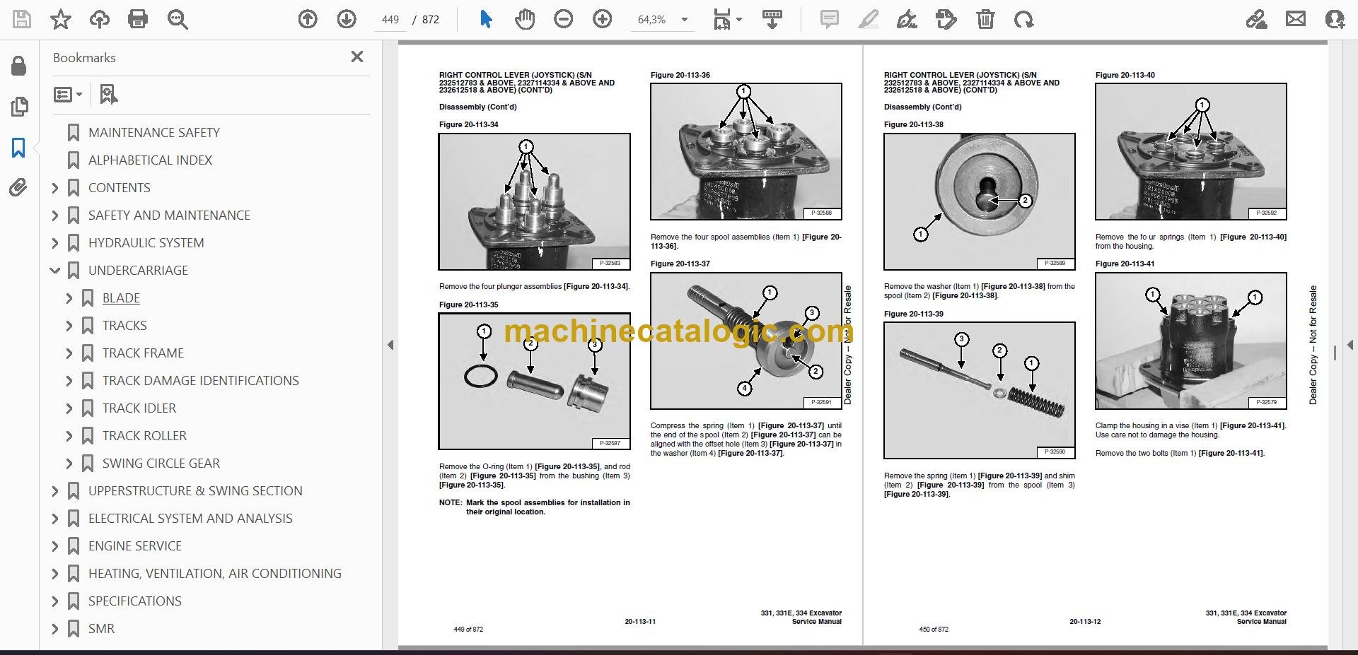
- RIGHT CONTROL LEVER (JOYSTICK) (S/N 232512783 & ABOVE, 2327114334 & ABOVE AND 232612518 & ABOVE)
- Testing
- Handle Removal And Installation
- Joystick Assembly Removal And Installation
- Parts Identification
- Disassembly
- Assembly
- HYDRAULIC FILTER
- HYDRAULIC RESERVOIR
- OIL COOLER
- DIRECT TO TANK VALVE
- Removal And Installation
- Disassembly And Assembly
- BUILD UP VALVE
- Description
- Removal And Installation
- Disassembly And Assembly
- CASE DRAIN FILTER
- Removal And Installation
- Continued On Next Page
- UNDERCARRIAGE
- BLADE
- TRACKS
- Track Lug Height
- Adjustment
- Rubber Track Removal And Installation
- Steel Track Removal And Installation
- TRACK FRAME
- Disassembly And Assembly
- Recoil Spring Disassembly And Assembly
- TRACK DAMAGE IDENTIFICATIONS
- Cutting Of Steel Cords
- Abrasion Of Embedded Metals
- Separation Of Embedded Metals
- Separation Of Embedded Metals Due To Corrosion
- Cuts On The Lug Side Rubber
- Cracks On The Lug Side Rubber Due To Fatigue
- Lug Abrasion
- Cracks And Cuts On The Lug Side Rubber
- Abrasion Of The Track Roller Side
- Cuts On The Edges Of Track Roller Side
- TRACK IDLER
- Parts Identification (S/N 232511877 & Below, 23271165 & Below And 232611488 & Below)
- Disassembly (S/N 232511877 & Below, 232711165 & Below And 232611488 & Below)
- Assembly (S/N 232511877 & Below, 232711165 & Below And 232611488 & Below)
- Parts Identification (S/N 232511878 & Above, 23271166 & Above And 232611489 & Above)
- Disassembly (S/N 232511878 & Above, 232711166 & Above And 232611489 & Above)
- Assembly (S/N 232511878 & Above, 232711166 & Above And 232611489 & Above)
- TRACK ROLLER
- Parts Identification (S/N 232511877 & Below, 232711165 & Below And 232611488 & Below)
- Disassembly (S/N 232511877 & Below, 23271165 & Below And 232611488 & Below)
- Assembly (S/N 232511877 & Below, 23271165 & Below And 232611488 & Below)
- Parts Identification (S/N 232511878 & Above, 232711166 & Above And 232611489 & Above)
- Disassembly (S/N 232511878 & Above, 23271166 & Above And 232611489 & Above)
- Assembly (S/N 232511878 & Above, 23271166 & Above And 232611489 & Above)
- SWING CIRCLE GEAR
- Removal And Installation
- Swing Bearing Removal
- Swing Bearing Installation
- Alignment Pins (Not Threaded)
- Continued On Next Page
- Continued On Next Page
- UPPERSTRUCTURE & SWING SECTION
- UPPERSTRUCTURE
- Removal And Installation
- Swing Bearing Removal
- Swing Bearing Installation
- Alignment Pins (Not Threaded)
- ROPS CANOPY
- CAB
- Removal And Installation
- Door Removal And Installation
- Front Window Removal And Installation
- Lower Front Window Removal And Installation
- Right Side Rear Sliding Window Removal And Installation
- Right Side Front Sliding Window Removal And Installation
- Right Side Panel And Window Assembly Removal And Installation
- Door, Left Side, Rear And Upper Front Window Removal And Installation
- SEAT AND MOUNT
- RIGHT CONSOLE
- Console Cover Removal And Installation
- Console Base Removal And Installation
- LEFT CONSOLE
- Lower Console Cover Removal And Installation
- Upper Console Cover Removal And Installation
- Compression Spring Removal And Installation
- Lock Lever Removal And Installation
- Upper Console Removal And Installation
- Console Switch Removal And Installation
- Disassembly And Assembly
- Console Base Removal And Installation
- ENGINE SPEED CONTROL
- BLADE CONTROL
- Lever Removal And Installation
- Linkage Removal And Installation
- Linkage Bar Removal And Installation
- Lower Linkage Removal And Installation
- RIGHT PEDAL AND LINKAGE
- Pedal Removal And Installation
- Right Pedal Disassembly And Assembly
- TRAVEL CONTROLS
- Removal And Installation
- Disassembly And Assembly
- FLOOR MAT AND FLOOR PANELS
- FUEL TANK
- HORN
- SWING FRAME
- Boom Swing Bracket Removal And Installation
- Boom Swing Bracket Hose Installation
- Bushing Removal
- Bushing Installation
- BOOM
- Removal And Installation
- Boom Bushing Removal And Installation
- ARM
- Removal And Installation
- Arm To Boom Bushing Removal And Installation
- Arm To Bucket And Bucket Link Bushing Removal And Installation
- EXTENDIBLE ARM
- Removal And Installation
- Disassembly And Assembly
- BUCKET
- Bucket Teeth Removal And Installation
- Bucket Side Cutting Edge Removal And Installation
- TAILGATE
- Removal And Installation
- Release Rod Removal And Installation (Early Models)
- Latch Removal And Installation (Early Models)
- Latch Removal And Installation (Later Models)
- X-CHANGE™
- Removal And Installation
- Disassembly
- Assembly
- RIGHT SIDE COVER
- ELECTRICAL SYSTEM AND ANALYSIS
- ELECTRICAL SCHEMATICS
- ELECTRICAL SYSTEM INFORMATION
- Troubleshooting Chart
- Description
- Fuse Location
- BATTERY
- Servicing
- Removal And Installation
- Using A Booster Battery (Jump Starting)
- ALTERNATOR
- Adjusting The Alternator Belt
- Removal And Installation
- Alternator Identification
- Charging System Check
- Alternator Voltage Test
- Low Voltage Test
- High Voltage Test
- Rectifier Continuity (Diode) Test
- Alternator Regulator Test
- Disassembly
- Stator Continuity Test
- Stator Ground Test
- Rotor Continuity Test
- Rotor Ground Test
- Assembly
- STARTER
- Removal And Installation
- Parts Identification
- Disassembly
- Inspection And Repair
- Assembly
- LIGHTS
- Removal And Installation
- Disassembly And Assembly
- FUEL LEVEL SENDER
- Removal And Installation
- Testing
- DIAGNOSTICS SERVICE CODE
- Number Codes List
- Continued On Next Page
- ENGINE SERVICE
- TROUBLESHOOTING
- SPARK ARRESTOR MUFFLER
- AIR CLEANER
- RADIATOR
- ENGINE COMPONENTS AND TESTING
- Valve Clearance Adjustment
- Engine Compression Checking
- Fuel Shutoff Solenoid Adjustment
- Fuel Shutoff Solenoid Removal And Installation
- Fuel Injection Pump Check
- Fuel Injection Pump Removal And Installation
- Fuel Injection Pump Timing
- Fuel Injector Nozzles
- Fuel Injector Nozzles Removal And Installation
- Fuel Injector Nozzles Check
- ENGINE
- ENGINE FLYWHEEL
- Removal And Installation
- Flywheel Ring Gear
- RECONDITIONING THE ENGINE
- Cylinder Head Removal And Installation
- Cylinder Head Disassembly And Assembly
- Cylinder Head Servicing
- Cylinder Head Top Clearance
- Valve Guide Checking
- Reconditioning The Valve And Valve Seat
- Valve Spring
- Rocker Arm And Shaft Checking
- Timing Gearcase Cover Removal And Installation
- Idler Gear And Camshaft Removal And Installation
- Camshaft Servicing
- Idler Gear And Shaft Servicing
- Timing Gears Checking Backlash
- Fuel Camshaft Removal And Installation
- Fuel Camshaft Governor
- Crankshaft Gear Removal And Installation
- Oil Pump Removal And Installation
- Oil Pump Service
- Checking Engine Oil Pressure
- Oil Pump Relief Valve
- Piston And Connecting Rod Removal And Installation
- Piston And Connecting Rod Servicing
- Connecting Rod Alignment
- Crankshaft And Bearings Removal And Installation
- Crankshaft And Bearings, Servicing
- Cylinder Bore, Checking
- Water Pump Removal And Installation
- Water Pump Disassembly And Assembly
- Fan Removal And Installation
- Continued On Next Page
- HEATING, VENTILATION, AIR CONDITIONING
- HEATER COIL
- Removal And Installation With A/C
- Removal And Installation Without A/C
- HEATER/AC FAN
- Removal And Installation
- Disassembly And Assembly
- Resistor Removal and Installation
- Wire Connector Removal and Installation
- HEATER VALVE
- AIR CONDITIONING SYSTEM FLOW
- COMPONENTS
- SAFETY
- REGULAR MAINTENANCE
- Filter Elements Removal And Installation
- Compressor Drive Belt Inspection
- Cleaning The Condenser
- BASIC TROUBLESHOOTING
- Poor A/C Performance
- Cleaning The A/C Evaporator Coil & Heater Coil
- Compressor Drive Belt Inspection:
- Checking The Electrical System
- Engine Coolant By-Passing The Heater Valve
- GENERAL AIR CONDITIONING SERVICE GUIDELINES
- Compressor Oil
- Compressor Oil Check
- Component Replacement And Refrigeration Leaks
- SYSTEM TROUBLESHOOTING CHART
- Blower Motor Does Not Operate
- Blower Motor Operates Normally, But Air Flow Is Insufficient
- Insufficient Cooling Although Air Flow And Compressor Operation Are Normal
- The Compressor Does Not Operate At All, Or Operates Improperly
- Gauge Pressure Related Troubleshooting
- TEMPERATURE/PRESSURE
- AIR CONDITIONING SERVICE
- SYSTEM CHARGING AND RECLAMATION
- Reclamation Procedure
- Charging Procedure With A Manifold Gauge Set
- Charging Procedure
- COMPRESSOR
- Removal And Installation
- Compressor Clutch Disassembly
- CONDENSER
- RECEIVER/DRIER
- PRESSURE RELIEF VALVE
- PRESSURE SWITCH
- EVAPORATOR/HEATER UNIT
- Removal And Installation
- Disassembly And Assembly
- THERMOSTAT
- EXPANSION VALVE
- EVAPORATOR
- Removal And Installation
- Continued On Next Page
- SPECIFICATIONS
- HYDRAULIC EXCAVATOR SPECIFICATIONS
- Machine Dimensions (Standard Arm)
- Machine Dimensions (331E Extendible Arm)
- Machine Dimensions (334 Long Arm)
- Lifting Capacity
- Specifications
- Weights
- Controls
- Engine
- Electrical
- Hydraulic System
- Cylinder Cycle Time
- Swing System
- Hydraulic Cylinders
- Drive System
- Brakes
- Undercarriage
- STD Track Shoes
- Refill Capacities
- Digging Force
- ENGINE SPECIFICATIONS
- Fuel Injection Nozzles
- Fuel Injection Pump
- Cylinder Head
- Valves
- Valve Springs
- Valve Timing
- Rocker Arms
- Camshaft
- Tappet
- Cylinders
- Piston Rings
- Pistons
- Connecting Rods
- Oil Pump
- Crankshaft
- Timing Gear
- Thermostat
- Engine Bolt Torque
- Crankshaft Re-Grind Data
- TORQUE SPECIFICATIONS
- Torque For General SAE Bolts
- Torque For General Metric Bolts
- HYDRAULIC CONNECTION SPECIFICATIONS
- O-Ring Face Seal Connection
- Straight Thread O-Ring Fitting
- Tubelines And Hoses
- Flare Fitting
- O-Ring Flare Fitting
- Port Seal Fitting
- HYDRAULIC FLUID SPECIFICATIONS
- FUEL, COOLANT AND LUBRICANTS
- FUEL, COOLANT AND LUBRICANTS (CONT’D)
- CONVERSIONS
- Decimal And Millimeter Equivalents
- U.S. To Metric Conversion
- SMR
- 331/331E/334-1
- 331/331E/334-2
- 331/331E/334-3
- 331/331E/334-4
Bobcat Software
Bobcat PDF Manuals


