A Bobcat 632 is a small skid-steer-class loader that lives on tight jobsites, barns, and driveways, doing pallet work, dirt, and snow. The people who grab this service manual are the ones actually wrenching on it: shop mechanics, field techs, and owner-operators who are past warranty. They want correct teardown steps, pressure checks, and adjustment specs so the machine goes back out without a comeback. If your 632 falls in the listed serial range, this is the book you use to keep it earning.
What this manual helps you do
- Diagnose hydraulic and hydrostatic issues, trace leaks, and verify system pressures on a 632 in the SN 499311001-499399999 range
- Follow step-by-step removal and installation for drive chains, axles, pumps, and motors
- Rebuild and adjust major components like cylinders, control valves, and the Bob-Tach style attachment system
- Check, set, and verify engine-related items, from fuel and cooling systems to basic top-end work
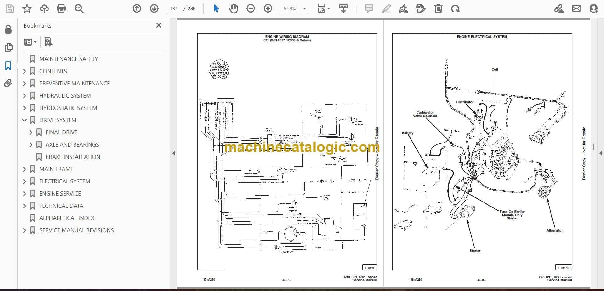
- Troubleshoot electrical problems using wiring diagrams and connector callouts specific to this serial group
Who this is for
This manual is for anyone maintaining or repairing a Bobcat 632 in a shop or rental yard, or an owner-operator doing their own repairs. If you only need how to run the controls or daily checks, you want the operator's handbook, not this service manual.
FAQ
Q: Is this a searchable PDF with readable wiring diagrams?
A: Yes, these manuals are normally scanned or native PDFs you can search, and wiring diagrams are clear enough to zoom and read pin labels.
Q: How do I know if it fits my exact machine?
A: Check your serial tag. If your 632 serial number falls between 499311001 and 499399999, this is the correct manual.
Q: Is this the right document if I'm just doing routine oil and filter changes?
A: It will cover that, but it's overkill. For simple fluids and intervals, the operator's handbook is easier to use.
If your 632's serial number is in that range and you're doing real repair work, this is the right manual. If the serial does not match, skip it and look for the correct range.
📘 Show Index
Table of Contents:
- MAINTENANCE SAFETY
- CONTENTS
- PREVENTIVE MAINTENANCE
- INTRODUCTION
- Symbols
- Serial Number Identification
- Loader Serial Number
- Engine Serial Number
- Pre–Delivery Inspection
- 30 Hour Inspection
- SERVICE INTERVALS
- ENGINE SERVICE
- Engine Oil And Filter
- Checking Oil
- Adding Oil
- Replacement Oil And Filter
- Crankcase Breather
- Air Cleaner System
- Fuel System (630, 632)
- Fuel Filter
- Fuel System (631)
- Fuel Pump
- Carburetor
- Carburetor Adjustment
- Idle Adjusting Needle
- Throttle Idle Adjustment
- Fuel Shut–Off
- Engine Cooling System
- Removing Coolant From System (632)
- Engine Electrical System (630, 631 & 632)
- Using An Extra Battery
- Installing New Battery
- Ignition System (630 & 632)
- Making Adjustment of Spark Plug Gap
- Making Adjustment of Point Gap
- HYDRAULIC FLUID AND FILTER
- TRANSMISSION AND DRIVE SYSTEM
- Drive Chains
- Brakes
- Fluid
- Tires
- Tire Rotation
- LOADER LUBRICATION
- BOB–TACH AND PIVOT PINS
- THE ENGINE MUFFLER
- HYDRAULIC SYSTEM
- HYDRAULIC / HYDROSTATIC SCHEMATICS
- HYDRAULIC CIRCUIT
- HYDRAULIC SYSTEM INFORMATION
- Keeping Bobcat Clean
- 37° Flare Connections
- Tubelines And Hoses
- Straight Thread O–Ring Connections
- HYDRAULIC TROUBLESHOOTING
- CONTROL VALVE
- Removing Control Valve
- Disassembly And Inspection Of Control Valve
- Assembling Control Valve
- Detent Spool Repair (Lift And Auxiliary Spools)
- Relief Valve
- Check Release Pressure
- Relief Valve Removal and Replacement
- Check Output of the Hydraulic Pump
- HYDRAULIC PUMP
- Checking Output Of Pump
- Hydraulic Pump Replacement
- HYDRAULIC CYLINDERS
- Checking Lift Cylinders
- Checking Tilt Cylinder
- Removing Hydraulic Cylinder
- Hydraulic Cylinder Repair
- Disassembly
- Assembly
- Tilt Cylinder Spacer (3’’ Tilt Cylinder)
- QUICK COUPLERS
- Restriction in the Quick Couplers (Early Models Only)
- HYDROSTATIC SYSTEM
- HYDROSTATIC CIRCUIT
- HYDROSTATIC TROUBLESHOOTING
- STEERING LINKAGE ADJUSTMENT
- REPLENISHING VALVE
- Checking Replenishing Valves
- BY–PASS VALVE
- PUMP ASSEMBLY – REMOVAL AND INSTALLATION
- Removing the Bronze Filter
- HYDROSTATIC PUMP ASSEMBLY – REPAIR
- Hydrostatic Pump Disassembly
- Hydrostatic Pump Inspection
- Yoke, Pintle Bearing, etc. – Installation
- #2 Pump Assembly
- Assemble Rotating Group
- Installing Rotating Group Into Housing
- #1 Pump Assembly
- Assemble Rotating Group
- Install Rotating Group Into Housing
- Installing Pumps to Manifold Block
- HYDROSTATIC MOTORS (630 S/N 15375 & Below and 632 S/N 15320 & Below)
- Removing The Hydrostatic Motors
- Installing Hydrostatic Motors
- Making The Special Tool For Holding Motor Sprockets
- Hose Location
- To Remove Air From The Hydrostatic System (S/N 12999 & Below)
- To Remove Air From The Hydrostatic System (S/N 13000 & Above)
- HYDROSTATIC MOTOR REPAIR (630 (S/N 15375 & Below) And 632 (S/N 15320 & Below)
- Hydrostatic Motor Disassembly and Inspection
- Hydrostatic Motor Assembly
- Start–Up Procedure For The Hydrostatic Motor
- HYDROSTATIC MOTOR REPAIR (630 – S/N 15376 & Above, 631 and 632 – S/N 15321 & Above)
- Disassembly Of The Hydrostatic Motor
- Hydrostatic Motor Inspection
- Assembly Of The Hydrostatic Motor
- Installing The Hydrostatic Motor
- Start–Up Procedure For The Hydrostatic Motor
- STEERING CONTROLS
- Installing Steering Linkages – 630–S/N 15300 & Below; 631–S/N 12253 & Below; 632–S/N 15450 & Below;
- Installing Steering Linkages; 630 (S/N 15301 & Above; 631 (S/N 12254 & Above); 632 (S/N 15451 & Above)
- DRIVE SYSTEM
- FINAL DRIVE
- AXLE AND BEARINGS
- Axle Bearing Removal
- Assembly And Installation
- BRAKE INSTALLATION
- MAIN FRAME
- ROPS REMOVAL AND INSTALLATION
- PIVOT PIN REPLACEMENT ON THE LIFT ARMS
- BOB–TACH
- Checking Bob–Tach Wedges
- Bob–Tach Removal
- Bob–Tach Installation
- Bob–Tach Pins
- Bob–Tach Over–Center Stop
- MAIN FRAME TO UPRIGHT FRAME BOLTS
- LIFT ARMS
- ELECTRICAL SYSTEM
- USING AN EXTRA BATTERY
- ROPS ELECTRICAL SYSTEM (Harness P/N 6558859)
- ROPS WIRING DIAGRAM (Harness P/N 6557492)
- 630 ENGINE ELECTRICAL SYSTEM (S/N 14999 & Below) (Harness P/N 6558862)
- ENGINE WIRING DIAGRAM 630 (S/N 14999 & Below) (Harness P/N 6558862)
- ENGINE ELECTRICAL SYSTEM 631 (S/N 4997 12999 & Below)
- ENGINE WIRING DIAGRAM 631 (S/N 4997 12999 & Below)
- ENGINE ELECTRICAL SYSTEM
- ENGINE WIRING DIAGRAM
- ELECTRICAL GENERAL INFORMATION
- Troubleshooting The Flywheel Alternator (630)
- PROBLEM: BATTERY OVERCHARGE
- PROBLEM: LOW/NO CHARGE
- To Check The Stator
- To Check the Rectifier Module
- To Check the Regulator Module
- ELECTRICAL CIRCUIT (631, 632)
- Electrical Troubleshooting
- CHART A BATTERY HAS LOW CHARGE
- CHART B BATTERY OVER–CHARGE
- ROPS Electrical Connector
- ALTERNATOR BELT ADJUSTMENT AND REPLACEMENT (631, 632)
- Adjustment
- Replacement
- Check Condition of Battery And Cables
- Check Alternator Wiring
- Check Alternator Output
- Check Regulator
- ALTERNATOR SERVICE
- Alternator Removal
- Alternator Disassembly
- Checking Rotor
- Checking Diode Trio
- Checking Rectifier
- Alternator Assembly and Installation
- STARTER
- Checking Starter
- Removing Starter
- Starter Disassembly
- Starter Cleaning and Inspection
- Brush Replacement
- Starter Assembly
- Check Electrical Wiring
- ENGINE SERVICE
- WISCONSIN ENGINE (630)
- TROUBLESHOOTING
- ENGINE IGNITION SYSTEM
- Distributor Maintenance
- Timing Procedure
- Spark Plugs
- CARBURETOR SERVICE
- Adjustments
- Float Adjustment
- Governor Adjustment
- REMOVAL OF ENGINE
- REMOVAL OF ACCESSORIES
- REMOVAL OF FLYWHEEL
- REMOVAL OF AIR HOUSING
- REMOVAL OF CARBURETOR AND MANIFOLD
- REMOVAL OF CYLINDER HEADS
- REMOVAL OF CAMSHAFT
- REMOVAL OF IDLER GEAR AND SHAFT
- REMOVAL OF OIL PAN
- REMOVAL OF OIL PUMP
- REMOVAL OF PISTONS AND CONNECTING RODS
- REMOVAL OF VALVE AND SEAT INSERTS
- REMOVAL OF CYLINDER BLOCK
- REMOVAL OF CRANKSHAFT
- REMOVAL OF CAMSHAFT
- REMOVAL OF VALVE TAPPETS
- INSTALLATION OF VALVE TAPPETS
- INSTALLATION OF CAMSHAFT
- INSTALLATION OF CRANKSHAFT
- INSTALLATION OF CYLINDER BLOCKS
- INSTALLATION OF PISTON RINGS
- INSTALLATION OF VALVES AND SEAT INSERTS
- INSTALLATION OF PISTONS AND CONNECTING RODS
- INSTALLATION OF OIL PUMP
- OIL PAN INSTALLATION
- INSTALLATION OF IDLER GEAR AND SHAFT
- INSTALLATION OF GEAR COVER
- INSTALLATION OF CYLINDER HEAD
- INSTALLATION OF CARBURETOR AND MANIFOLD ASSEMBLY
- INSTALLATION OF AIR HOUSING
- INSTALLATION OF FLYWHEEL
- INSTALLATION OF ACCESSORIES
- GOVERNOR SERVICE
- DEUTZ ENGINE–FL411D (631)
- TROUBLESHOOTING
- FUEL SYSTEM
- Fuel And Control Linkage Adjustment
- Venting Air From Fuel System
- Fuel Filter
- Fuel Lift Pump
- Fuel Injection Pump Checking
- Removal Of Fuel Injection Pump
- Fuel Injection Pump Service
- To Install Fuel Injection Pump
- Adjustment Of Fuel Delivery
- FUEL INJECTION NOZZLES
- Removal Of Fuel Injection Nozzles
- Disassembly & Repair Of Fuel Injection Nozzles
- Installation Of Fuel Injection Nozzles
- ENGINE INFORMATION
- ENGINE REMOVAL
- BLOWER FAN
- Removal
- Installation
- Disassembly
- Assembly
- CYLINDER HEAD AND VALVES
- Removal
- Disassembly
- Repair and Assembly
- Installation Of Cylinder Head
- CYLINDERS, PISTONS, CONNECTING RODS
- Assembly
- OIL PUMP, FILTER HOUSING AND RELIEF VALVE
- Oil Pump Removal
- Installation
- Oil Pressure Relief Valve
- Filter Housing
- ENGINE FRONT COVER
- Removal
- Disassembly & Inspection
- Assembly
- Installation
- GOVERNOR
- Removal and Disassembly
- Assembly and Installation
- CAMSHAFT (Engine Must Be Removed)
- Removal
- Installation
- Crankshaft Removal
- Crankshaft Inspection
- Crankshaft Assembly
- FLYWHEEL
- DEUTZ ENGINE–F2L511 (631)
- TROUBLESHOOTING
- ENGINE MOUNTS
- FUEL SYSTEM
- Venting Air From Fuel System
- Fuel Filters
- Fuel Lift Pump
- Removal Of Fuel Injection Pump
- Removal Of Injection Pump
- Fuel Injection Pump Service
- To Install Fuel Injection Pump
- Adjustment Of Fuel Delivery
- FUEL INJECTION NOZZLES
- Removal
- Disassembly And Repair Of Injector (In Shop)
- Installation Of Injector
- ENGINE INFORMATION
- ENGINE REMOVAL
- BLOWER FAN
- Removal Of Blower Fan
- Installation
- Disassembly
- Assembly
- CYLINDER HEAD AND VALVES
- Removal And Disassembly
- Repair And Assembly
- Checking Piston Crown Clearance And Installation Of Cylinder Head
- CYLINDER, PISTONS AND CONNECTING RODS
- OIL PUMP, FILTER HOUSING AND RELIEF VALVE
- Oil Pump Removal
- Installation
- Oil Pressure Relief Valve
- ENGINE FRONT COVER
- Removal
- Disassembly And Inspection
- Assembly
- Installation
- GOVERNOR
- Removal And Disassembly
- Assembly And Installation
- CAMSHAFT (Engine Must Be Out Of Machine)
- Removal
- Installation
- Crankshaft Removal
- Crankshaft Inspection
- Crankshaft Assembly
- FLYWHEEL
- ENGINE OIL COOLER
- FORD ENGINE (632)
- TROUBLESHOOTING
- CHECKS AND ADJUSTMENTS
- Engine Oil Pressure
- Valve Clearance
- Checking Engine Compression
- Understanding The Results Of The Test
- Carburetor, Throttle And Governor Adjustments
- Ignition System
- Coil To Coil Ground Voltmeter Test
- Spark Plug Wires Resistance Test
- Spark Plug Test
- Distributor Tests
- Dwell Angle Check
- Spark Strength Tests
- Ignition System Tests
- Battery To Coil Voltmeter Test
- Starting Ignition Circuit Voltmeter Test
- Breaker Point Gap Adjustment
- Ignition Timing
- Timing Mark Locations
- Initial Ignition Timing
- CARBURETOR REPAIR
- ENGINE DIAGNOSIS AND TESTING
- Camshaft Lobe Lift
- Crankshaft End Play
- Flywheel Face Alignment Check
- Camshaft End Play
- ENGINE OVERHAUL
- Cylinder Head
- Valve Guides
- Grinding Valve Seats
- Valves
- Grinding Valves
- Select Fitting Of Valves
- Camshaft Repair
- Crankshaft
- Reconditioning Crankshaft Journals
- To Check Crankshaft Or Connecting Rod Bearings With Plastigage
- Pistons, Pins And Rings
- To Install Pistons
- To Install Piston Rings
- Installing Piston Pins
- Valve Rocker Arm And/Or Shaft Assembly
- Push Rods
- Cylinder Block
- Cylinder Head
- Tappets
- Camshaft
- Crankshaft Inspection
- Flywheel Inspection
- Connecting Rods
- Pistons, Pins And Rings
- Main And Connecting Rod Bearings
- Cylinder Block
- OIL PUMP
- REMOVAL OF ENGINE
- VALVE ROCKER ARM COVER, ROCKER ARM AND/OR SHAFT
- Removal And Disassembly
- Installation
- VALVE PUSHROD
- INTAKE MANIFOLD
- CYLINDER HEAD
- VALVE SPRING, RETAINER AND STEM SEAL (CYLINDER HEAD REMOVED)
- VALVE SPRING, RETAINER AND STEM SEAL (CYLINDER HEAD INSTALLED)
- WATER PUMP
- ENGINE FRONT COVER, TIMING CHAIN AND CRANKSHAFT SPROCKETS
- Installation
- Removal
- Remove Timing Cover
- FRONT OIL SEAL
- TIMING CHAIN TIGHTENER
- CAMSHAFT AND VALVE LIFTERS
- FLYWHEEL RING GEAR
- OIL PAN
- OIL PUMP
- CRANKSHAFT REAR OIL SEAL
- MAIN BEARINGS
- CONNECTING ROD BEARINGS
- PISTONS AND CONNECTING RODS
- CRANKSHAFT
- CAMSHAFT BEARINGS
- Removal of Camshaft
- Installation
- TECHNICAL DATA
- ENGINE SPECIFICATIONS, 630 (WISCONSIN)
- 630 LOADER SPECIFICATIONS
- OPERATIONAL & PERFORMANCE
- ENGINE
- LOADER HYDRAULICS
- ELECTRICAL
- DRIVE SYSTEM
- CAPACITIES
- TIRES
- MACHINE WEIGHT
- ENGINE SPECIFICATIONS, 630 (Wisconsin)
- Fuel Specifications
- Engine Oil
- Valve Mechanism
- Crankshaft
- Idler Gear
- Connecting Rod
- Piston, Piston Pin, Piston Rings
- Ignition System
- Distributor Advance Characteristics
- Starter
- Engine Torque Specifications
- ENGINE SPECIFICATIONS, 631 (DEUTZ)
- 631 LOADER SPECIFICATIONS
- OPERATIONAL & PERFORMANCE
- ENGINE
- LOADER HYDRAULICS
- ELECTRICAL
- DRIVE SYSTEM
- CAPACITIES
- TIRES
- MACHINE WEIGHT
- ENGINE SPECIFICATIONS – F2L411D, 631 (Deutz)
- Fuel System
- Governor, Front Cover And Throttle
- Cylinder Head And Valves
- Cylinder, Piston And Connecting Rod
- Camshaft, Crankshaft, Bearings
- Lubrication System
- Torque Specifications (Deutz Engine)
- Special Tools (Deutz)
- ENGINE SPECIFICATIONS – F2L511, 631 (Deutz)
- Fuel System
- Governor, Front Cover And Throttle
- Cylinder Head And Valves
- Cylinder, Piston And Connecting Rod
- Camshaft, Crankshaft, Bearings
- Lubrication System
- Torque Specifications
- Special Tools (F2L511 Deutz)
- ENGINE SPECIFICATIONS, 632 (FORD)
- 632 LOADER SPECIFICATIONS
- OPERATIONAL & PERFORMANCE
- ENGINE
- LOADER HYDRAULICS
- ELECTRICAL
- DRIVE SYSTEM
- CAPACITIES
- TIRES
- MACHINE WEIGHT
- ENGINE SPECIFICATIONS, 632 (FORD)
- Fuel Specifications
- Fuel System
- Engine Oil
- Lubrication System
- Cylinder Heads
- Valve Mechanism
- Camshaft
- Crankshaft
- Connecting Rod
- Piston
- Piston Pin
- Piston Rings
- Cylinder Block
- Ignition System
- Starter
- Torque Specifications For Engine
- Special Tools (Ford)
- Carburetor Tool
- TECHNICAL DATA
- LOADER TORQUE SPECIFICATIONS
- HYDRAULIC/HYDROSTATIC TRANSMISSION FLUID
- Hydrostatic System Specifications
- SPECIAL TOOLS
- Main Frame & Hydraulic Tools
- Hydrostatic System Tools
- CONVERSIONS
- U.S. To Metric Conversion
- Decimal And Millimeter Equivalents
- ALPHABETICAL INDEX
- SERVICE MANUAL REVISIONS
- 630–1
- 630–2
- 630–3
- 630–4
- 630-5
Bobcat Software
Bobcat PDF Manuals