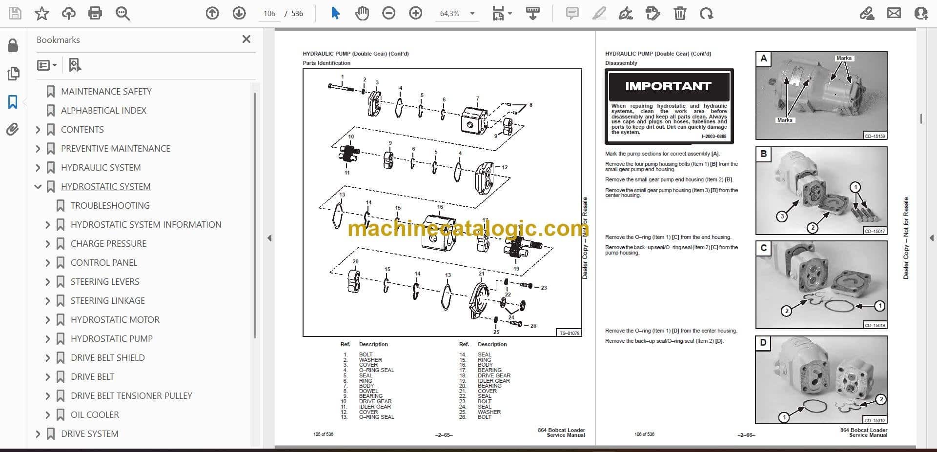
The Bobcat 864 is a skid-steer-class loader that lives in the same world as a Cat 236 or Deere 320, running a diesel engine, hydrostatic drive, and high-flow hydraulics for buckets, augers, hammers, and so on. People grab this service manual when the 864 is out of warranty and they're done guessing, or when a field tech needs the right sequence to diagnose a no-drive, weak hydraulics, or an electrical fault. Around my shop, this is what I'd open before tearing into pumps, drive motors, or chasing wiring ghosts on an older 864.
What this manual helps you do
- Trace and troubleshoot hydraulic and hydrostatic drive problems on the 864 loader
- Check and set pressures on the main and charge circuits with proper test ports and procedures
- Follow teardown and reassembly steps for pumps, drive motors, cylinders, and major mechanicals
- Diagnose and repair electrical and wiring issues using circuit diagrams for this serial range
- Replace and adjust linkages, controls, and Bob-Tach components with correct sequences and specs
Who this is for
This is for a small contractor, owner-operator, shop mechanic, or rental fleet tech working on a Bobcat 864 in the 516911001-516999999 serial range. If you only need how to start, operate, or basic maintenance intervals, you want the operator's handbook instead, not this manual.
FAQ
Q: Is this a searchable PDF and are the wiring diagrams readable?
A: These manuals are usually supplied as searchable PDFs, and the wiring diagrams are meant to be zoomed in on a screen or printed for bench use.
Q: How do I know if it fits my exact 864?
A: Check your machine's serial tag. If it falls between 516911001 and 516999999, this is the correct service manual series.
Q: Is this the right document if I'm rebuilding or diagnosing, not just changing oil?
A: Yes, this is the workshop service manual, meant for real repair work, not routine operator maintenance.
Bottom line: If you have a Bobcat 864 in that serial range and you're doing your own diagnostics or rebuilds, this is the manual you want. If you just need basic operating info, skip it.
📘 Show Index
Table of Contents:
- MAINTENANCE SAFETY
- ALPHABETICAL INDEX
- CONTENTS
- FOREWORD
- SAFETY INSTRUCTIONS
- FIRE PREVENTION
- SERIAL NUMBER LOCATIONS
- LOADER SERIAL NUMBER
- ENGINE SERIAL NUMBER
- DELIVERY REPORT
- BOBCAT LOADER IDENTIFICATION
- PREVENTIVE MAINTENANCE
- SERVICE SCHEDULE
- LIFTING AND BLOCKING THE LOADER
- TRANSPORTING THE BOBCAT LOADER
- TOWING THE LOADER
- Procedure (Without Coupler)
- Procedure (With Coupler)
- LIFT ARM SUPPORT DEVICE
- Engaging The Lift Arm Support Device
- Disengaging The Lift Arm Support Device
- REMOTE START SWITCH
- OPERATOR CAB
- Description
- Raising The Operator Cab
- Lowering The Operator Cab
- Emergency Exit
- SEAT BAR RESTRAINT SYSTEM
- Description
- Inspecting The Seat Bar
- Maintaining The Seat Bar
- SEAT BAR RESTRAINT SYSTEM (ADVANCED HAND CONTROLS)
- FUEL SYSTEM
- Fuel Specifications
- Filling the Fuel Tank
- Fuel Filter
- Removing Air From The Fuel System
- ENGINE LUBRICATION SYSTEM
- Checking Engine Oil
- Replacing The Oil And Filter
- ENGINE COOLING SYSTEM
- Cleaning The Cooling System
- HYDRAULIC/HYDROSTATIC SYSTEM
- Checking And Adding Fluid
- Hydraulic/Hydrostatic Filter Replacement
- Replacing The Hydraulic Fluid
- LUBRICATING THE LOADER
- HYDRAULIC SYSTEM
- HYDRAULIC / HYDROSTATIC SCHEMATICS
- HYDRAULIC SYSTEM INFORMATION
- TROUBLESHOOTING
- LIFT CYLINDER
- Checking The Lift Cylinder(s)
- Removal And Installation
- TILT CYLINDER
- Checking The Tilt Cylinder(s)
- Removal And Installation
- Rod End Seal
- HYDRAULIC CYLINDER
- Lift Cylinder Identification
- Tilt Cylinder Identification
- Disassembly
- Assembly
- MAIN RELIEF VALVE
- Checking The Main Relief Valve At The Front Auxiliary Hydraulics
- Checking The Main Relief Valve Without Auxiliaries
- Removal And Installation
- Adjustment
- BICS™ VALVE
- Lift Arm By–Pass Orifice
- Check Valve
- Lock Valve
- BICS™ Valve Solenoid
- Removal And Installation
- HYDRAULIC CONTROL VALVE
- Auxiliary Pressure Relief Block (864H)
- Removal And Installation
- Identification Chart
- Disassembly and Assembly
- Load Check Valve
- Lift Base End Restrictor
- Main Relief Valve
- Port Relief Valve
- Anti–Cavitation Valve/Port Relief Valve
- Anti–Cavitation Valve
- Rubber Boot
- Lift Spool and Detent
- Tilt Spool and Centering Spring
- Auxiliary Spool
- Auxiliary Electric Solenoid
- H Port – Auxiliary Section
- Inspection
- Spool Seal Installation
- LIFT ARM BY–PASS CONTROL VALVE
- LIFT ARM BY–PASS CONTROL VALVE MOUNT BRACKET
- Removal And Installation
- Disassembly And Assembly
- HYDRAULIC PUMP
- Checking The Output Of The Pump
- Removal and Installation
- Parts Identification
- Disassembly
- Inspection
- Assembly
- HYDRAULIC PUMP (Double Gear)
- Checking The Output Of The High Flow Pump
- Removal and Installation
- Disassembly
- Parts Identification
- Inspection
- Assembly
- HYDRAULIC/HYDROSTATIC FILTER HOUSING
- HYDRAULIC FLUID RESERVOIR
- Draining The Hydraulic Fluid Reservoir
- Removal And Installation
- CONTROL PEDALS
- Pedal Adjustment
- Removal and Installation
- PEDAL INTERLOCK LINKAGE
- Pedal Interlock Linkage Adjustment
- Removal and Installation
- CROSSBAR LINKAGE
- Removal And Installation
- Inspection
- REAR AUXILIARY DIVERTER–864 STANDARD FLOW
- Disassembly
- Inspection
- Solenoid Testing
- Assembly
- SELECT VALVE (864H)
- Checking The High Flow Pump Relief Valve
- Removal And Installation
- Disassembly And Assembly
- Solenoid Testing
- BUCKET POSITION VALVE
- Solenoid Removal And Installation
- Solenoid Testing
- Removal And Installation
- Disassembly And Assembly
- HYDROSTATIC SYSTEM
- TROUBLESHOOTING
- HYDROSTATIC SYSTEM INFORMATION
- Replenishing Valve Function
- CHARGE PRESSURE
- CONTROL PANEL
- STEERING LEVERS
- Removal And Installation
- Disassembly And Assembly
- STEERING LINKAGE
- Removal And Installation
- Neutral Adjustment
- HYDROSTATIC MOTOR
- Removal And Installation
- Parts Identification
- Disassembly
- Inspection
- Assembly
- HYDROSTATIC PUMP
- Removal And Installation
- Replenishing/High Pressure Relief Valve
- Charge Pressure Relief Valve
- Parts Identification (Right Half)
- Parts Identification (Left Half)
- Hydraulic Pump Removal
- Disassembly
- Assembly
- DRIVE BELT SHIELD
- DRIVE BELT
- Adjusting The Drive Belt
- Replacing The Drive Belt
- DRIVE BELT TENSIONER PULLEY
- Removal And Installation
- Disassembly And Assembly
- Tension Spring
- OIL COOLER
- DRIVE SYSTEM
- PARKING BRAKE PEDAL
- Removal And Installation
- Disassembly And Assembly
- BRAKE BLOCK
- Removal And Installation
- Disassembly And Assembly
- Traction Lock By–Pass Knob
- TRACK
- Checking Track Tension
- Adjusting Track Tension
- Removal And Installation
- TRACK IDLER (Front)
- Removal And Installation
- Parts Identification
- Disassembly
- Assembly
- TRACK IDLER (Rear)
- Removal And Installation
- Parts Identification
- Disassembly
- Assembly
- TRACK ROLLER
- Removal And Installation
- Parts Identification
- Disassembly
- Assembly
- TRACK HOUSING
- TRACK DAMAGE IDENTIFICATION
- Cutting Of Steel Cords
- Abrasion Of Embedded Metals
- Separation Of Embedded Metals
- Cuts On The Lug Side Rubber
- Separation Of Embedded Metals Due To Corrosion
- Lug Abrasion
- Cracks And Cuts On The Lug Side Rubber
- Cracks On The Lug Side Rubber Due To Fatigue
- Abrasion Of The Track Roller Side
- Cuts On The Edges Of Track Roller Side
- MAIN FRAME
- SEAT BAR
- Removal And Installation
- Assembling Components
- Compression Spring Disassembly And Assembly
- OPERATOR CAB GAS CYLINDER
- Removal And Installation
- Disassembly And Assembly
- OPERATOR CAB
- OPERATOR SEAT
- BOB–TACH
- Inspection And Maintenance
- Bob–Tach Lever And Wedge
- Removal And Installation
- Pivot Pin Bushing And Seal Replacement
- LIFT ARMS
- REAR GRILL
- REAR DOOR
- Removal And Installation
- Adjusting The Rear Door Latch
- FUEL TANK
- Removal And Installation
- Fuel Level Sender
- Fuel Pick–up Screen/Check Valve
- ELECTRICAL SYSTEM
- ELECTRICAL SCHEMATICS
- TROUBLESHOOTING
- ELECTRICAL SYSTEM INFORMATION
- Description
- Fuse Location
- Solenoid Testing
- BATTERY
- Removal And Installation
- Servicing The Battery
- Using A Booster Battery
- ALTERNATOR BELT
- Adjusting The Alternator Belt
- ALTERNATOR
- Alternator Output Test
- Rectifier (Diode) Test
- Alternator Regulator Test
- Removal And Installation
- Disassembly
- Stator Continuity Test
- Stator Ground Test
- Rotor Continuity Test
- Rotor Ground Test
- Rectifier Continuity (Diode) Test
- Assembly
- STARTER
- Removal And Installation
- Parts Identification
- Disassembly And Assembly
- External Pinion
- Inspection And Repair
- Magnetic Switch Test
- No Load Test
- STANDARD INSTRUMENT PANEL
- FRONT LIGHTS
- RELAY SWITCHES
- ENGINE SERVICE
- TROUBLESHOOTING
- ENGINE SPEED CONTROL
- Removal And Installation
- Speed Control Linkage
- Speed Control Cable
- ENGINE MUFFLER
- AIR CLEANER
- AIR CLEANER
- Housing, Removal And Installation
- RADIATOR
- Oil Cooler, Removal And Installation
- COOLING FAN
- Drive Tension Pulley, Removal And Installation
- Gearbox/Blower Housing, Removal And Installation
- Blower, Removal And Installation
- Gearbox, Checking And Maintaining
- Gearbox, Parts Identification
- Gearbox, Disassembly
- Gearbox, Assembly
- Gearbox, Checking Backlash
- ENGINE COMPONENTS AND TESTS
- Engine Compression, Checking
- Glow Plug, Checking
- Fuel Shut–Off Solenoid, Checking
- Fuel Shut–Off Solenoid Removal and Installation
- Fuel Injection Pump, Removal
- Fuel Injection Pump Timing
- Fuel Injection Pump Installation
- Fuel Injector Removal and Installation
- Fuel Injector Checking
- Fuel Injector Disassembly
- Fuel Injector Assembly
- Timing Belt, Inspection
- Timing Belt, Removal
- Timing Belt, Installation
- Timing Belt, Replacement In the Loader
- Valve Clearance Adjustment
- Valve Timing, Checking
- Thermostat, Oil Pressure Control Valves & Heater Connections
- ENGINE AND ENGINE MOUNTS
- Removal And Installation
- Engine Mount Replacement
- FLYWHEEL AND HOUSING
- Flywheel Removal And Installation
- Ring Gear Removal And Installation
- Flywheel Housing Removal And Installation
- RECONDITIONING THE ENGINE
- Deutz Engine Tools Identification Chart
- Disassembly
- Assembly
- Cylinder, Checking
- Camshaft Bearing, Checking
- Camshaft Bearing, Removal And Installation
- Control Rod Guide Bushing, Removal
- Control Rod Guide Bushing, Installation
- Rear Cover Seal, Removal And Installation
- Crankshaft, Checking
- Connecting Rod, Checking
- Piston, Checking
- Piston Pin, Checking
- Piston Rings, Installation
- Piston Installation On the Connecting Rod
- Cylinder Head, Disassembly
- Valves, Checking
- Valve Seats, Checking
- Valve Spring, Checking
- Cylinder Head, Assembly
- Rocker Arm and Bracket, Checking
- Front Cover, Disassembly
- Front Cover, Assembly
- Turbo Charger, Removal and Installation
- Crankshaft Gear Mounting Bolt Torque Procedure
- SYSTEMS ANALYSIS
- BICS™
- Inspecting The BICS™ Controller (Engine STOPPED – Key ON)
- Deactivation Of The Auxiliary Hydraulics System (Engine STOPPED – Key ON)
- Inspecting The Seat Bar Sensor (Engine RUNNING)
- Inspecting The Traction Lock (Engine RUNNING)
- Inspecting The Lift Arm By–Pass Control
- Additional Inspection For Loaders With Advanced Hand Controls
- BOBCAT INTERLOCK CONTROL SYSTEM (BICS™)
- BICS SYSTEM CONTROLLER
- Troubleshooting Guide
- Removal And Installation
- SEAT BAR SENSOR
- Troubleshooting Guide
- Seat Bar Sensor Test
- Removal And Installation
- BICS™ Controller Seat Bar Sensor Circuit Test
- TRACTION LOCK
- Troubleshooting Guide
- Removal And Installation
- BOSS® DIAGNOSTIC TOOL
- SENDER AND SENSOR
- Service Checks
- Components
- RPM SENSOR
- MONITOR SERVICE CODES
- TROUBLESHOOTING THE BOSS® & LCD DISPLAY
- BOSS®UNIT
- BOSS® INSTRUMENT PANEL
- PWM MODULE
- PWM TROUBLESHOOTING
- PWM CONTROL HANDLE
- PWM ELECTRIC SOLENOID
- ELECTRICAL/HYDRAULIC CONTROLS REFERENCE
- Controls Identification Chart
- SPECIFICATIONS
- LOADER SPECIFICATIONS
- LOADER DIMENSIONS
- PERFORMANCE
- CONTROLS
- ENGINE
- HYDRAULIC SYSTEM
- ELECTRICAL
- DRIVE SYSTEM
- CAPACITIES
- TRACKS
- GROUND PRESSURE
- ENGINE SPECIFICATIONS (BF4M1011)
- General
- Fuel System
- Valve And Valve Guide And Seat Insert
- Piston And Rings
- Connecting Rod
- Cylinder Head And Block
- Crankshaft And Main Bearings
- Camshaft And Bearings
- Oil Pump
- ENGINE SPECIFICATIONS (BF4M1011F)
- General
- Fuel System
- Valve And Valve Guide And Seat Insert
- Piston And Rings
- Connecting Rod
- Cylinder Head And Block
- Crankshaft And Main Bearings
- Camshaft And Bearings
- Oil Pump
- ENGINE TORQUE
- TORQUE SPECIFICATIONS FOR LOADER
- HYDRAULIC CONNECTION SPECIFICATIONS
- O–ring Face Seal Connection
- Straight Thread O–ring Fitting
- Tubelines And Hoses
- Flare Fitting
- O–ring Flare Fitting
- Port Seal Fitting
- HYDRAULIC/HYDROSTATIC FLUID SPECIFICATIONS
- STANDARD TORQUE SPECIFICATIONS FOR BOLTS
- DECIMAL AND MILLIMETER EQUIVALENTS
- U.S. TO METRIC CONVERSION
- ADVANCE HAND CONTROL SYSTEM (A.H.C)
- ADVANCE HAND CONTROL ELECTRICAL SCHEMATICS
- A.H.C. COMPONENTS
- TROUBLESHOOTING (A.H.C.)
- ACTUATOR VOLTAGE TEST
- HANDLE CONTROL UNIT TEST
- BOBCAT INTERLOCK CONTROL SYSTEM (BICS™)
- A.H.C./PWM CONTROLLER
- Removal And Installation
- Test
- Description
- Conditions
- Troubleshooting Chart
- Handle Testing
- Solenoid Coil Testing
- HANDLE CONTROL UNIT
- Removal And Installation
- Control Unit Connector
- SWITCH HANDLE
- A. H. C. HANDLE
- A.H.C. STEERING LEVER
- Removal And Installation
- Steering Lever Boot
- ACTUATORS
- Removal And Installation
- Disassembly And Assembly
- Mounting Plate
- BICS™ VALVE
- Lift Arm By–Pass Orifice
- Check Valve
- Lock Valve
- BICS™ Valve Solenoid
- Removal And Installation
- HYDRAULIC CONTROL VALVE
- Removal And Installation
- Identification Chart
- Disassembly And Assembly
- Load Check Valve
- Lift Base End Restrictor
- Main Relief Valve
- Port Relief Valve (Lift)
- Anti–Cavitation/Port Relief Valve
- Port Relief Valve (Tilt)
- Anti–Cavitation Valve
- Rubber Boot
- Lift And Tilt Spool
- Inspection
- Auxiliary Spool
- Auxiliary Electrical Solenoid
- Spool Seal Installation
- H–Port Auxiliary Section
- SERVICE MANUAL REVISION
Bobcat Software
Bobcat PDF Manuals