$ 0
0
$ 0
0

Bobcat B200 Backhoe Loader Service Manual (SN 570211001-570299999)

Format: PDF (Printable Document)

File Language: English

File Pages: 662

File Size: 26.55 MB (Speed Download Link)

Brand: Bobcat

Model: B200 Backhoe Loader

Book No: 6901848

Serial No: SN 570211001-570299999

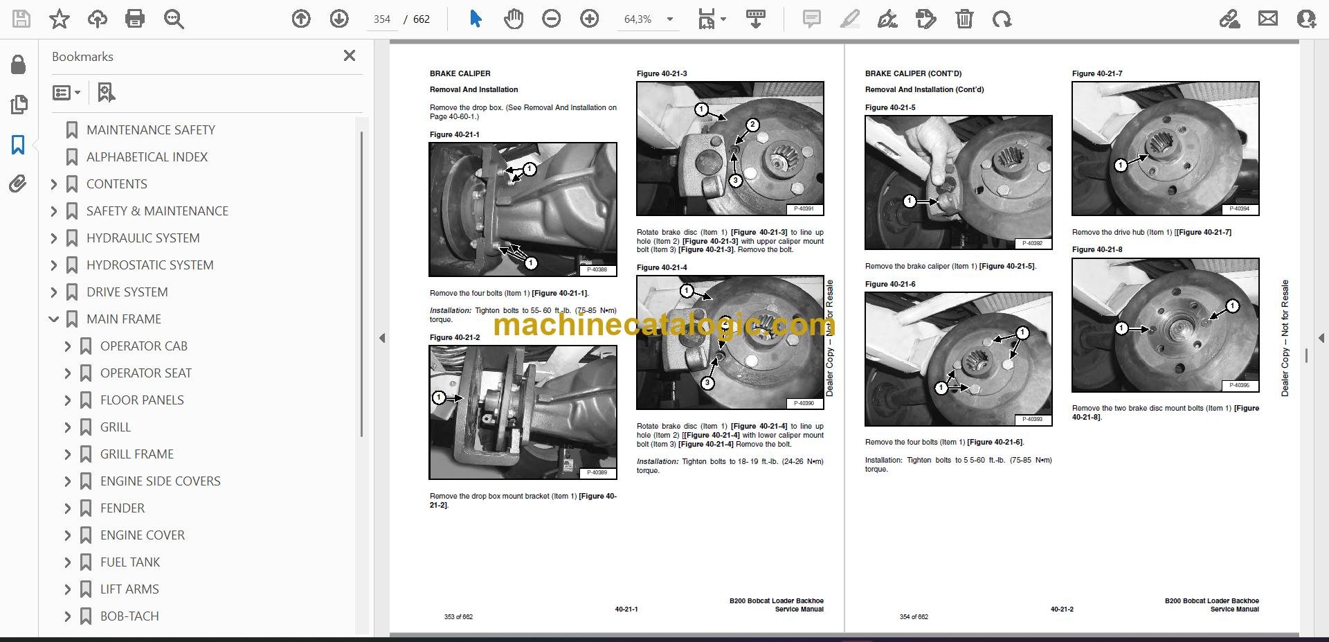
Type of Document: Service Manual

Categories: ,

$ 45

Share:

Bobcat B200 Backhoe Loader Service Manual (SN 570211001-570299999)

The B200 is a small backhoe loader, so think trenching utilities, loading trucks, and cleanup work on tight jobsites. When one of these goes down, the guys who grab the service manual are the ones actually turning wrenches, not just moving paper. They want to know how it comes apart, what to check in what order, and what the specs are so they only fix it once and get back to billable hours.

What this manual helps you do

  • Trace hydraulic problems in the loader and backhoe circuits, then pressure-test and isolate bad valves, cylinders, or hoses.
  • Check and adjust the hydrostatic and drivetrain systems so the machine pulls right and stops eating components.
  • Follow step-by-step tear-down and reassembly on major pieces like the engine, axles, cylinders, and pumps when you're rebuilding in the shop.
  • Diagnose electrical issues using wiring diagrams so you can chase down no-start, dead lights, or dead controls without guessing.
  • Verify adjustments on controls, linkages, and brakes after repairs so the machine operates safely and feels right to the operator.

Who this is for

This manual is for a small contractor, owner-operator, rental fleet, or shop mechanic who actually works on a Bobcat B200 and wants dealer-level repair info. If you only need to know how to run the machine or daily checks, you want the operator's handbook instead, not this.

FAQ

Q: Is this a searchable PDF, and can you read the wiring diagrams?

A: These manuals are usually scanned or native PDF, searchable, with wiring diagrams clear enough to zoom in and follow wire colors and pin labels.

Q: My serial number is between 570211001 and 570299999, is this the right one?

A: Yes, this manual is aimed at B200 machines in that serial number range.

Q: I'm just doing basic maintenance, is this overkill?

A: For simple fluids and filters, it's more than you need, but if you're doing real repairs or diagnostics, this is the right document type.

Bottom line, if you own or maintain a Bobcat B200 in that serial range and you actually crack wrenches on it, this is the manual you want. If you just operate it, skip this and get the operator's book.

📘 Show Index

Table of Contents:

  • MAINTENANCE SAFETY
  • ALPHABETICAL INDEX
  • CONTENTS
    • SAFETY INSTRUCTIONS
      • Fire Prevention
    • SERIAL NUMBER LOCATION
      • Loader Backhoe Serial Number
      • Engine Serial Number
    • DELIVERY REPORT
    • BOBCAT LOADER IDENTIFICATION
  • SAFETY & MAINTENANCE
    • LIFTING AND BLOCKING THE LOADER BACKHOE
      • Procedure
    • LIFT ARM SUPPORT DEVICE
      • Installing The Lift Arm Support Device
      • Removing The Lift Arm Support Device
    • ENGINE COVER
    • TRANSPORTING THE LOADER BACKHOE
      • Procedure
    • TOWING THE LOADER BACKHOE
      • Procedure
    • AXLE TOE-IN
      • Adjustment
    • SERVICE SCHEDULE
      • Chart
    • AIR CLEANER SERVICE
      • Replacing Filter Element
    • ENGINE COOLING SYSTEM
      • Coolant Replacement
    • FUEL SYSTEM
      • Fuel Specifications
      • Filling The Fuel Tank
      • Fuel Filter
      • Removing Air From The Fuel System
    • ENGINE LUBRICATION SYSTEM
      • Checking Engine Oil
      • Oil Chart
      • Replacing Oil And Filter
    • HYDRAULIC/HYDROSTATIC SYSTEM
      • Checking And Adding Fluid
      • Cleaning The Cooler
      • Replacing Hydraulic/Hydrostatic Filter
      • Replacing Hydraulic Fluid
    • REAR AXLE
      • Checking Oil Level
      • Draining Oil
    • FRONT AXLE
      • Checking Oil Level
      • Draining Oil
    • BACKHOE BOOM LOCK
      • Disengaging The Boom Lock
      • Engaging Boom Lock
    • BOB-TACH HAND LEVER
      • Inspection And Maintenance
    • ALTERNATOR BELT
      • Adjusting The Alternator Belt
    • LUBRICATING THE LOADER BACKHOE
    • TIRE MAINTENANCE
      • Wheel Nuts
      • Mounting
      • Tire Pressure
  • HYDRAULIC SYSTEM
    • HYDRAULIC/HYDROSTATIC SCHEMATIC
    • HYDRAULIC SYSTEM INFORMATION
      • Troubleshooting
      • Description
    • ARM CYLINDER
      • Checking
      • Removal And Installation
      • Parts Identification
      • Disassembly
      • Assembly
    • BOOM CYLINDER
      • Checking
      • Removal And Installation
      • Parts Identification
      • Disassembly
      • Assembly
    • SWING CYLINDER
      • Removal And Installation
      • Bushing Removal And Installation
      • Parts Identification (Left Side)
      • Parts Identification (Right Side)
      • Disassembly
      • Assembly
    • BUCKET CYLINDER
      • Checking
      • Removal And Installation
      • Parts Identification
      • Disassembly
      • Assembly
    • STABILIZER CYLINDER
      • Checking
      • Removal And Installation
      • Parts Identification
      • Disassembly
      • Assembly
    • TILT CYLINDER
      • Checking
      • Removal And Installation
      • Parts Identification (Left Side)
      • Parts Identification (Right Side)
      • Disassembly
      • Assembly
    • LIFT CYLINDER
      • Checking
      • Removal And Installation
      • Parts Identification
      • Disassembly
      • Assembly
    • STEERING CYLINDER
      • Removal And Installation
      • Parts Identification
      • Disassembly And Assembly
      • Inspection
    • MAIN RELIEF VALVE
      • Testing The Main Relief Valve
      • Adjustment
    • PORT RELIEF VALVE (BACKHOE CONTROL VALVE)
      • Testing And Adjusting (Arm Control)
      • Testing And Adjusting (Boom Control)
      • Testing And Adjusting (Boom Swing Control)
    • PORT RELIEF VALVE (LOADER CONTROL VALVE)
      • Testing And Adjusting (Bucket Tilt)
      • Testing And Adjusting (Front Auxiliary)
    • LOADER CONTROL VAVLE
      • Removal And Installation
      • Parts Identification
      • Disassembly And Assembly
      • Inlet/Outlet Valve Section
      • Lift Arm Valve Section
      • Tilt Valve Section
      • Auxiliary Valve Section
    • BACKHOE CONTROL VALVE
      • Removal And Installation
      • Parts Identification
      • Disassembly And Assembly
      • Inlet/Outlet Valve Section
      • Arm Valve Section
      • Tilt Valve Section
      • Right Stabilizer Valve Section
      • Left Stabilizer Valve Section
      • Boom Valve Section
      • Boom Swing Valve Section
      • Outlet Valve Section
    • HYDRAULIC FLUID RESERVOIR
      • Removal And Installation
      • Filter Removal And Installation
    • HYDRAULIC FILTER HOUSING
      • Removal And Installation
      • Disassembly
      • Assembly
    • GEAR PUMP
      • Removal And Installation
      • Parts Identification
      • Disassembly And Assembly
      • Inspection
    • STEERING PUMP
      • Removal And Installation
      • Parts Identification
      • Disassembly
      • Inspection
      • Assembly
    • TRAVEL PEDAL
      • Removal And Installation
      • Parts Identification
      • Disassembly And Assembly
  • HYDROSTATIC SYSTEM
    • HYDROSTATIC SYSTEM INFORMATION
      • Troubleshooting Chart
      • Replenishing Valve Function
    • OIL COOLER
      • Removal And Installation
      • Parts Identification
      • Disassembly
      • Assembly
    • HYDROSTATIC DRIVE MOTOR
      • Removal And Installation
      • Parts Identification
      • Disassembly
      • Inspection
      • Assembly
    • HYDROSTATIC PUMP
      • Removal And Installation
      • Parts Identification
      • Disassembly
      • Inspection
      • Assembly
    • HYDROSTATIC TESTING
      • Pump Adjustment
  • DRIVE SYSTEM
    • PARKING BRAKE
      • Lever Removal And Installation
      • Cable Removal And Installation
      • Adjustment
    • BRAKE CALIPER
      • Removal And Installation
      • Parts Identification
      • Disassembly And Assembly
    • BRAKE CALIPER
      • Removal And Installation
      • Parts Identification
      • Disassembly And Assembly
    • REAR AXLE
      • Removal
      • Installation
    • AXLE AND DIFFERENTIAL (REAR)
      • Troubleshooting Chart
      • General Information
      • Wheel Hub/Axle Parts Identification
      • Wheel Hub/Axle Disassembly
      • Differential Parts Identification
      • Differential Disassembly
      • Differential Inspection
      • Pinion Group Parts identification
      • Pinion Group Disassembly
      • Pinion Group Inspection
      • Pinion Group Assembly
      • Differential Assembly
      • Wheel Hub/Axle Assembly
    • FRONT AXLE
      • Removal
      • Installation
    • DRIVESHAFT
      • Removal And Installation
    • DROP BOX
      • Removal And Installation
      • Parts Identification
      • Disassembly
      • Inspection
      • Assembly
  • MAIN FRAME
    • OPERATOR CAB
      • Removal And Installation
      • Cab Mount Removal And Installation
    • OPERATOR SEAT
      • Removal And Installation
    • FLOOR PANELS
      • Left Front Panel Removal And Installation
      • Right Front Panel Removal And Installation
      • Rear Panel Removal And Installation
    • GRILL
      • Removal And Installation
    • GRILL FRAME
      • Removal And Installation
    • ENGINE SIDE COVERS
      • Removal And Installation
    • FENDER
      • Removal And Installation
    • ENGINE COVER
      • Removal And Installation
    • FUEL TANK
      • Removal And Installation
      • Fuel Fill Screen Removal And Installation
    • LIFT ARMS
      • Removal And Installation
    • BOB-TACH
      • Removal And Installation
      • Bob-Tach Lever And Wedge
      • Pivot Pin Bushing Removal And Installation
    • ARM
      • Removal And Installation
      • Arm Pivot Bushing Removal And Installation
    • BOOM
      • Removal And Installation
      • Boom Pivot Bushing Removal And Installation
    • SWING FRAME
      • Removal And Installation
      • Bushing Removal And Installation
    • X-CHANGE™
      • Removal And Installation
    • CAB DOOR
      • Removal And Installation
    • STABILIZER
      • Removal And Installation
    • FRONT AXLE PIVOT FRAME
      • Removal
      • Installation
      • Bushing Removal And Installation
  • ELECTRICAL SYSTEM AND ANALYSIS
    • ELECTRICAL SCHEMATIC
    • ELECTRICAL SYSTEM INFORMATION
      • Troubleshooting Chart
      • Description
      • Fuse Location
    • BATTERY
      • Removal And Installation
      • Servicing The Electrical System
      • Using A Booster Battery (Jump Starting)
    • ALTERNATOR
      • Adjusting The Alternator Belt
      • Description
      • Tests
      • Alternator Output Test
      • Full Field Test
      • Alternator Regulator Test
      • Alternator Regulator Test With Voltmeter
      • Removal And Installation
      • Parts Identification
      • Pulley Removal And Installation
      • Disassembly And Assembly
      • Rotor Continuity Test
      • Stator Continuity Test
      • Rectifier Continuity (Diode) Test
      • Brush Length
    • STARTER
      • Removal And Installation
      • Checking The Starter In The Loader
      • Parts Identification
      • Disassembly
      • Inspection And Repair
      • No Load Test
      • Assembly
    • FRONT LIGHTS
      • Bulb Removal And Installation
      • Housing Removal And Installation
    • TURN INDICATOR LIGHTS (FRONT)
      • Bulb Removal And Installation
    • TURN INDICATOR LIGHTS (REAR)
      • Bulb Removal And Installation
    • CAB LIGHTS
      • Bulb Removal And Installation
      • Housing Removal And Installation
    • FUEL LEVEL SENDER
      • Removal And Installation
    • INSTRUMENT PANEL
      • Removal And Installation
  • ENGINE SERVICE
    • TROUBLESHOOTING
      • Chart
    • ENGINE SPEED CONTROL
      • Removal And Installation
      • Cable Removal And Installation
    • MUFFLER
      • Removal And Installation
    • AIR CLEANER
      • Removal And Installation
    • RADIATOR
      • Removal And Installation
    • ENGINE COMPONENTS AND TESTING
      • Checking Engine Compression
      • Checking Glow Plugs
      • Glow Plug Removal And Installation
      • Fuel Shut-Off Solenoid Removal And Installation
      • Checking Fuel Injection Pump
      • Fuel Injection Pump Removal And Installation
      • Fuel Injection Pump Timing
      • Fuel Injector Nozzles Removal And Installation
      • Checking Fuel Injector, Nozzles
      • Thermostat Removal And Installation
      • Water Pump Removal And Installation
    • ENGINE
      • Removal And Installation
      • Mount Replacement
    • RECONDITIONING THE ENGINE
      • Timing Gear Case Cover Removal And Installation
      • Oil Pump Removal And Installation
      • Crankshaft Front Seal Removal And Installation
      • Engine Speed Control Plate Removal And Installation
      • Idle Limit And Fuel Limit Adjustment
      • Exhaust Manifold Removal And Installation
      • Valve Cover Removal And Installation
      • Rocker Arm Removal And Installation
      • Push Rod Removal And Installation
      • Tappet Removal And Installation
      • Water Flange Removal And Installation
      • Cylinder Head Removal And Installation
      • Checking Piston Top Clearance
      • Cylinder Head Disassembly And Assembly
      • Servicing The Cylinder Head
      • Combustion Chamber Removal And Installation
      • Idler Gear Removal And Installation
      • Camshaft Removal And Installation
      • Fuel Camshaft Removal And Installation
      • Oil Pan Removal And Installation
      • Governor Shaft Removal And Installation
      • Governor Fork Lever Removal And Installation
      • Piston Removal And Installation
      • Checking The Piston And Connecting Rod
      • Connecting Rod Alignment
      • Piston Ring Gap
      • Piston Ring Installation
      • Connecting Rod Installation
      • Checking Engine Cylinder Bore
      • Crankshaft Removal And Installation
      • Checking Crankshaft Journal And Block Bearing
      • Checking Crankshaft Journal And Main Bearing
      • Connecting Rod Journal
      • Checking The End Play Of The Crankshaft
      • Crankshaft Alignment
      • Engine Timing Installation
      • Timing Gear Backlash, Idler Gear And Crankshaft
      • Idler Gear And Camshaft Gear
      • Idler Gear And Fuel Camshaft Gear
      • Fuel Camshaft Gear And Governor Shaft Gear
    • FLYWHEEL HOUSING
      • Removal And Installation
    • FLYWHEEL
      • Removal And Installation
      • Ring Gear Removal And Installation
    • RUBBER DRIVE COUPLER
      • Removal And Installation
      • Disassembly
    • TURBOCHARGER
      • Removal And Installation
  • SPECIFICATIONS
    • LOADER SPECIFICATIONS
      • Loader Backhoe Dimensions
      • Performance
      • Controls
      • Engine
      • Electrical
      • Drive System
      • Capacities
      • Tires
    • ENGINE SPECIFICATIONS
      • Engine Compression
      • Fuel Injection Nozzles
      • Fuel Injection Pump
      • Cylinder Head
      • Valves
      • Valve Springs
      • Rocker Arms
      • Camshaft
      • Cylinders
      • Piston Rings
      • Pistons
      • Crankshaft
      • Oil Pump
      • Thermostat
      • Grinding Specifications for the Crankshaft
    • LOADER BACKHOE TORQUE
      • Specifications
    • TORQUE SPECIFICATIONS FOR BOLTS
      • Torque For General Metric Bolts
    • HYDRAULIC/HYDROSTATIC FLUID SPECIFICATIONS
      • Specifications
    • CONVERSIONS
      • Decimal And Millimeter Equivalents
      • U.S. To Metric Conversion
  • SMR
    • B200-1
    • B200-2
    • B200-3
    • B200-4
    • B200-5
    • B200-6
    • B200-7

Bobcat Software

Bobcat PDF Manuals

Related Manuals

0
    0
    Your Cart
    Your cart is emptyReturn to Shop