$ 0
0
$ 0
0

Bobcat B730 Backhoe Loader Service Manual (SN B53S11000-B53S99999)

Format: PDF (Printable Document)

File Language: English

File Pages: 1350

File Size: 47.59 MB (Speed Download Link)

Brand: Bobcat

Model: B730 Backhoe Loader

Book No: 7402295

Serial No: SN B53S11000-B53S99999

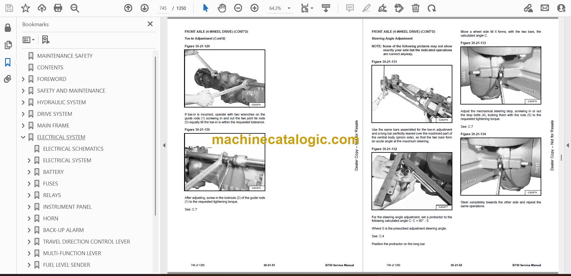
Type of Document: Service Manual

Categories: ,

$ 45

Share:

Bobcat B730 Backhoe Loader Service Manual (SN B53S11000-B53S99999)

The B730 is a tractor-loader-backhoe that spends its life loading trucks, trenching, and doing utility work. The manual is what I keep on the bench when a machine comes off rent with hydraulic issues, electrical faults, or needs scheduled 500-hour work. People reach for this when they're chasing a fault code, rebuilding a cylinder, or need the right sequence to split major components without breaking anything expensive.

What this manual helps you do

  • Diagnose hydraulic problems in the loader, backhoe, and steering circuits, then verify pressures with the correct test ports and sequences
  • Trace and troubleshoot electrical faults using wiring diagrams, connector callouts, and step-by-step checks with a meter
  • Follow teardown and reassembly procedures for major components like axles, brakes, cylinders, and the backhoe swing/boom assemblies
  • Check and set adjustments on linkages, brakes, loader/backhoe geometry, and machine-level settings after parts replacement
  • Plan and carry out 50/250/500-hour services with the right inspection points, fluid change procedures, and torque references

Who this is for

This is for a small contractor, owner-operator, rental yard, or shop mechanic who actually turns wrenches on a Bobcat B730. If you only need basic controls, safety, or daily checks, you want the operator's handbook instead, not this service manual.

FAQ

Q: Is this a searchable PDF and are the wiring diagrams readable?

A: Yes, these manuals are usually supplied as searchable PDFs, and the wiring diagrams are laid out so you can zoom in and read wire colors and pin numbers.

Q: How do I know if it matches my machine?

A: Check your serial plate. If your B730 serial number falls between B53S11000 and B53S99999, this is the right manual.

Q: Is this the right document if I'm only ordering parts?

A: For part numbers you want the parts catalog. Use this service manual when you're actually diagnosing or repairing the machine.

Bottom line: If you own or maintain a Bobcat B730 in the B53S11000-B53S99999 range and you plan to do real repairs, this is the manual you want. If you just operate the machine, it's overkill.

📘 Show Index

Table of Contents:

  • MAINTENANCE SAFETY
  • CONTENTS
  • FOREWORD
    • FOREWORD
    • SAFETY INSTRUCTIONS
      • Before Operation
      • Safe Operation Is The Operator’s Responsibility
      • Safe Operation Needs A Qualified Operator
      • Avoid Silica Dust
      • Dismantling And Disposal
      • General Safety Information
      • Crushing And Burning Prevention
      • Fire And Explosion Prevention
      • Machine Startup Safety
      • Engine Startup And Operating Safety
      • Machine Operating Safety
      • Machine Parking Safety
      • Machine Transporting Safety
      • Machine Towing Safety
      • Machine Maintenance Safety
      • During Maintenance
      • Hydraulic Lines And Hoses
    • PUBLICATIONS AND TRAINING RESOURCES
    • SERIAL NUMBER LOCATION
      • Backhoe Loader Serial Number
      • Engine Serial Number
      • Other Serial Numbers
    • DELIVERY REPORT
    • BOBCAT BACKHOE LOADER IDENTIFICATION
  • SAFETY AND MAINTENANCE
    • SERVICE SCHEDULE
      • Maintenance Intervals
      • Lubrication Chart
      • Inspection Checkbook
    • LIFTING AND BLOCKING THE MACHINE
      • Procedure
    • TOWING THE MACHINE
      • Procedure
    • TRANSPORTING THE BACKHOE LOADER ON A TRAILER
      • Loading And Unloading
    • STOPPING THE ENGINE AND LEAVING THE MACHINE
    • STORAGE AND RETURN TO SERVICE
      • Storage
      • Return To Service
    • OPERATOR CAB
      • Description
      • Cab Doors
      • Windshield Wipers
      • Side Windows
      • Rear Windows
    • EMERGENCY EXIT
    • BACKHOE BOOM / SWING LOCK
      • Locking And Unlocking The Backhoe Boom / Swing Lock
    • APPROVED LIFT ARM SUPPORT DEVICE
      • Description
      • Installing The Approved Lift Arm Support Device
      • Removing The Approved Lift Arm Support Device
    • TIRE MAINTENANCE
      • Wheel Nuts
      • Rotating The Tires
      • Wheel Replacement
      • Mounting The Tires
      • Tire Pressure
    • ENGINE COVER
      • Opening And Closing
    • GRILLE
      • Removing And Installing
    • ENGINE AIR CLEANER
      • Description
      • Cleaning The Outer Air Filter
      • Replacing The Air Filters
    • FUEL SYSTEM
      • Fuel Specifications
      • Biodiesel Blend Fuel
      • Filling The Fuel Tank
      • Draining The Fuel Tank
      • Fuel Filters
    • ENGINE LUBRICATION SYSTEM
      • Engine Oil Chart
      • Checking And Adding Engine Oil
      • Removing And Replacing Oil And Filter
    • ENGINE COOLING SYSTEM
      • Cooling System
      • Cleaning The Cooling System
      • Checking And Adding Coolant
      • Removing And Replacing Coolant
    • HYDRAULIC SYSTEM
      • Hydraulic / Hydrostatic Fluid Chart
      • Checking And Adding Hydraulic Fluid
      • Removing And Replacing The Hydraulic Filters
      • Removing And Replacing The Hydraulic Fluid
    • REAR AXLE
      • Axle And Reduction Gears
      • Checking And Adding Oil
      • Draining Oil
      • Check And Adding Reduction Gear Oil
      • Draining Reduction Gear Oil
      • Parking Brake Inspection / Adjustment
    • TRANSMISSION
      • Checking And Adding Oil
      • Removing And Replacing Oil
      • Replacing The Filter Element
    • ALTERNATOR AND FAN BELT
      • Belt Checking
      • Belt Adjustment
      • Belt Replacement
    • ATTACHMENT COUPLING SYSTEMS
      • Loader Attachment Coupling Inspection And Maintenance
      • Backhoe Attachment Coupling Inspection And Maintenance
    • LUBRICATING THE MACHINE
      • Lubrication Locations
  • HYDRAULIC SYSTEM
    • HYDRAULIC / HYDROSTATIC SCHEMATICS
    • HYDRAULIC SYSTEM INFORMATION
      • Glossary Of Hydraulic / Hydrostatic Symbols
    • HYDRAULIC SYSTEM
      • Tests And Hydraulic Pressure Test
      • Test Ports
      • Blocks
      • ON-OFF Solenoid Valve
      • ON-OFF Pressure Reducing Valve
      • Steering Priority Valve
      • Steering Pressure Test
      • Pilot Pressure Test
      • Pilot Pressure Regulation Block
      • Priority Valve
    • RETURN LINE CHECK VALVE
      • Removal And Installation
    • LOADER ARM LIFT CYLINDERS
      • Removal And Installation
      • Parts Identification
      • Disassembly
      • Inspection
      • Assembly
    • LOADER BUCKET (TILT) CYLINDER
      • Removal And Installation
      • Parts Identification
      • Disassembly
      • Inspection
      • Assembly
    • CLAMPSHELL CYLINDER
      • Removal And Installation
      • Parts Identification
      • Disassembly
      • Inspection
      • Assembly
    • BACKHOE BOOM CYLINDER
      • Removal And Installation
      • Parts Identification
      • Disassembly
      • Inspection
      • Assembly
    • BACKHOE ARM CYLINDER
      • Removal And Installation
      • Parts Identification
      • Disassembly
      • Inspection
      • Assembly
    • BACKHOE BUCKET CYLINDER
      • Removal And Installation
      • Parts Identification
      • Disassembly
      • Inspection
      • Assembly
    • TELESCOPIC ARM CYLINDER
      • Removal And Installation
      • Parts Identification
      • Disassembly
      • Inspection
      • Assembly
    • BACKHOE SWING CYLINDERS
      • Removal And Installation
      • Parts Identification
      • Disassembly
      • Inspection
      • Assembly
    • BACKHOE STABILIZER CYLINDERS
      • Removal And Installation
      • Parts Identification
      • Disassembly
      • Inspection
      • Assembly
    • SIDE SHIFT LOCK CYLINDERS
      • Removal And Installation
    • HYDRAULIC PUMP
      • Description
      • Removal And Installation
    • BACKHOE CONTROL VALVE
      • Port Locations (ISO Pattern)
      • Removal And Installation
    • BRAKE PEDAL AND BOOSTER
      • Removal And Installation
    • HYDRAULIC FLUID RESERVOIR
      • Description
      • Removal And Installation
      • Hydraulic Fluid Screen Removal And Installation
      • Hydraulic Filter Removal And Installation
      • Hydraulic Suction Strainer Removal And Installation
    • LOADER CONTROL VALVE
      • Port Locations (Mechanical Controls)
      • Port Locations (Pilot Controls)
      • Removal And Installation
      • Pressure Relief Valves (PRV) Test And Unloading Valve Test
    • STEERING COLUMN AND UNIT
      • Removal And Installation
    • BACKHOE DISTRIBUTOR BLOCK
      • Removal And Installation
  • DRIVE SYSTEM
    • TRANSMISSION (MECHANICAL 2-WHEEL DRIVE)
      • Description
      • Removal And Installation
      • Tightening Torques
      • Plugs And Filters Disassembly
      • Plugs And Filters Assembly
      • Converter And Oil Pump Disassembly
      • Converter And Oil Pump Assembly
      • Pipes Disassembly
      • Pipes Assembly
      • Hydraulic Control Valve Disassembly
      • Hydraulic Control Valve Assembly
      • Transmission Housing Disassembly
      • Transmission Housing Assembly
      • Shafts A – D Disassembly
      • Shafts A – D Assembly
      • Shafts B – C Disassembly
      • Shafts B – C Assembly
      • Speed Controls Disassembly
      • Speed Controls Assembly
      • Troubleshooting
    • TRANSMISSION (MECHANICAL 4-WHEEL DRIVE)
      • Description
      • Removal And Installation
      • Tightening Torques
      • Plugs And Filters Disassembly
      • Plugs And Filters Assembly
      • Converter And Oil Pump Disassembly
      • Converter And Oil Pump Assembly
      • Pipes Disassembly
      • Pipes Assembly
      • Hydraulic Control Valve Disassembly
      • Hydraulic Control Valve Assembly
      • 4-Wheel Drive Solenoid Valve Disassembly
      • 4-Wheel Drive Solenoid Valve Assembly
      • Transmission Housing Disassembly
      • Transmission Housing Assembly
      • Shafts A – D Disassembly
      • Shafts A – D Assembly
      • Shafts B – C Disassembly
      • Shafts B – C Assembly
      • Shaft E Disassembly
      • Shaft E Assembly
      • Speed Controls Disassembly
      • Speed Controls Assembly
      • Troubleshooting
    • TRANSMISSION (AUTOSHIFT 4-WHEEL DRIVE)
      • Description
      • Removal And Installation
      • Tightening Torques
      • Filters Disassembly
      • Filters Assembly
      • Check Ports
      • Oil Pump Disassembly
      • Oil Pump Assembly
      • Switches And Sensors Disassembly
      • Switches And Sensors Assembly
      • Hydraulic Control Valve Disassembly
      • Hydraulic Control Valve Assembly
      • SAHR Brake Solenoid Valve Disassembly
      • SAHR Brake Solenoid Valve Assembly
      • SAHR Brake Group Disassembly
      • SAHR Brake Group Assembly
      • Manual Parking Brake Disassembly
      • Manual Parking Brake Assembly
      • Front Half-Housing Disassembly
      • Front Half-Housing Assembly
      • Rear Cover – Shafts Disassembly
      • Rear Cover – Shafts Assembly
      • Gear Pistons Disassembly
      • Gear Pistons Assembly
      • Speed Gears Shift Rails Adjustment
      • Speed Gears Switches Check
      • Shafts A – D Disassembly
      • Shafts A – D Assembly
      • Shafts B – C Disassembly
      • Shafts B – C Assembly
      • 4-Wheel Drive Shaft Disassembly
      • 4-Wheel Drive Shaft Assembly
      • Shift Rails – Forks Disassembly
      • Shift Rails – Forks Assembly
      • SAHR Parking Brake
      • 4WS Front Half-Housing Disassembly
      • 4WS Front Half-Housing Assembly
      • 4-Wheel Drive Shaft – Coaxial TLB1 Disassembly
      • 4-Wheel Drive Shaft – Coaxial TLB1 Assembly
    • FRONT AXLE (2-WHEEL DRIVE)
      • Description
      • Removal And Installation
      • Tightening Torques
      • Steering Cylinder Group Disassembly
      • Steering Cylinder Group Assembly
      • Wheel Hub Group Disassembly
      • Wheel Hub Group Assembly
      • Axle Beam Group Disassembly
      • Axle Beam Group Assembly
      • Toe-In Adjustment
      • Troubleshooting
    • FRONT AXLE (4-WHEEL DRIVE)
      • Description
      • Removal And Installation
      • Tightening Torques
      • Steering Cylinder Group Disassembly
      • Steering Cylinder Group Assembly
      • Epicyclic Reduction Gear Group Disassembly
      • Epicyclic Reduction Gear Group Assembly
      • Wheel Hub Group Disassembly
      • Wheel Hub Group Assembly
      • Differential Support Group Disassembly
      • Differential Support Group Assembly
      • Bevel Gear Marking Test
      • Differential Group Disassembly
      • Differential Group Assembly
      • Pinion Group Disassembly
      • Pinion Group Assembly
      • Axle Beam Group Disassembly
      • Axle Beam Group Assembly
      • Toe-In / Steering Angle
      • Toe-In Adjustment
      • Steering Angle Adjustment
      • Wheel And Double U-Joint Group Disassembly
      • Wheel And Double U-Joint Group Assembly
      • Double U-Joint Seal Ring Replacement On Axle Beam Side
      • Double U-Joint Bushing Replacement On Axle Beam Side
      • Testing After Assembly
      • Troubleshooting
    • REAR AXLE
      • Description
      • Removal And Installation
      • Tightening Torques
      • Parking Brake Caliper Group Disassembly
      • Parking Brake Caliper Group Assembly
      • Epicyclic Reduction Gear Group Disassembly
      • Epicyclic Reduction Gear Group Assembly
      • Wheel Hub Group Disassembly
      • Wheel Hub Group Assembly
      • Axle Beam Trumpet Group Disassembly
      • Axle Beam Trumpet Group Assembly
      • Brake Group Disassembly
      • Brake Group Assembly
      • Differential Support Group Disassembly
      • Differential Support Group Assembly
      • Differential Group Disassembly
      • Differential Group Assembly
      • Differential Locking Group Disassembly
      • Differential Locking Group Assembly
      • Pinion Group Disassembly
      • Pinion Group Assembly
      • Testing After Assembly
      • Troubleshooting
    • FRONT SHAFT
      • Removal And Installation
    • REAR SHAFT
      • Removal And Installation
    • SERVICE BRAKE
      • Description
      • Bleeding The Brake Circuitry
      • Test Procedure
      • Troubleshooting
  • MAIN FRAME
    • BACKHOE BOOM / SWING LOCK
      • Removal And Installation
    • BUCKET TEETH
      • Removal And Installation
    • BACKHOE BOOM
      • Removal And Installation
    • CAB (PILOT CONTROL)
      • Removal And Installation
    • CAB (MECHANICAL CONTROL)
      • Removal And Installation
    • COUNTERWEIGHT
      • Removal And Installation
    • ENGINE COVER
      • Removal And Installation
    • FRONT MUDGUARD
      • Removal And Installation
    • PARKING LEVER
      • Removal And Installation
    • FUEL TANK
      • Removal And Installation
    • KINGPOST
      • Removal And Installation
    • SIDE SHIFT
      • Removal And Installation
    • BACKHOE ARM
      • Removal And Installation
    • FRONT CONSOLE
      • Removal And Installation
    • STABILIZER WEAR PADS
      • Adjustment
  • ELECTRICAL SYSTEM
    • ELECTRICAL SCHEMATICS
    • ELECTRICAL SYSTEM
      • Component Location
    • BATTERY
      • Battery Maintenance
      • Battery Testing
      • Battery Charging
      • Using A Booster Battery (Jump Starting)
      • Removing And Installing The Battery
      • Battery Disconnect Switch
    • FUSES
      • Location
      • Parts Identification (Synchroshuttle Transmission)
      • Parts Identification (Autoshift Transmission)
    • RELAYS
      • Location
      • Parts Identification (Synchroshuttle Transmission)
      • Parts Identification (Autoshift Transmission)
    • INSTRUMENT PANEL
      • Removal And Installation
    • HORN
      • Removal And Installation
    • BACK-UP ALARM
      • Inspection
      • Removal And Installation
    • TRAVEL DIRECTION CONTROL LEVER
      • Removal And Installation
      • Parts Identification
    • MULTI-FUNCTION LEVER
      • Removal And Installation
    • FUEL LEVEL SENDER
      • Removal And Installation
  • ENGINE SERVICE (TIER 2)
    • ENGINE INFORMATION
      • Introduction
      • Engine Views
      • Engine Identification
      • Safety Precautions
      • Safety Precautions When The Engine Is Cleaned
      • Engine Lift Equipment
      • Viton Seals
      • POWERPART Recommended Consumable Products
      • Troubleshooting
    • ENGINE SPECIFICATIONS
      • Basic Engine Data
      • Data And Dimensions
      • Thread Sealant
      • Standard Torque Values
      • Specific Torque Values
      • Compression Test Data
    • CYLINDER HEAD
      • General Description
      • Atomiser Cover
      • Rocker Cover
      • Rocker Arm
      • Valve Tip Clearances
      • Valve Springs
      • Removal
      • Installation
      • Valve And Valve Springs
      • Valve Guides
      • Inspection And To Correct
    • PISTON AND CONNECTING ROD ASSEMBLIES
      • General Description
      • Big End Bearing
      • Piston And Connecting Rod
      • Piston Rings
      • Piston And Connecting Rod Assembly
      • Piston And Piston Rings
      • Connecting Rod
      • Partially Finished Small End Bush
      • Piston Cooling Jets
    • CRANKSHAFT ASSEMBLY
      • General Description
      • Crankshaft Pulley
      • Rear End Oil Seal Assembly
      • To Remove And To Fit A Wear Sleeve
      • Thrust Washers
      • Main Bearings
      • Crankshaft
      • Balancer Unit
    • TIMING CASE AND DRIVE ASSEMBLY
      • General Description
      • Timing Cover
      • Mechanical Fuel Pump Gear
      • Electronic Fuel Pump Gear
      • Idler Gear and Hub
      • Heavy Duty Idler Gear
      • Camshaft Gear
      • Front Oil Seal
      • Timing Case
      • Crankshaft Gear
      • Camshaft And Tappets
    • CYLINDER BLOCK ASSEMBLY
      • General Description
      • Cylinder Block
      • Cylinder Bore
    • ENGINE TIMING
      • General Description
      • To Set Number 1 Piston To TDC On The Compression Stroke
      • To Check The Timing Of The Bosch VP30 Fuel Injection Pump
      • To Check The Timing Of The Bosch EPVE Fuel Injection Pump
      • To Adjust The Timing Of The Bosch EPVE Fuel Injection Pump
      • To Check The Timing Of The Delphi DP210 Fuel Injection Pump
      • To Check The Valve Timing
    • ASPERATION SYSTEM
      • General Description
      • Exhaust Elbow
      • Turbocharger Side Mount
      • Turbocharger Faults
      • Open Engine Breather
      • Natural Aspirated Engine Breather
      • Closed Engine Breather
    • LUBRICATION SYSTEM
      • General Description
      • Lubrication System Flow Diagram
      • Canister Type Oil Filter
      • Element Type Oil Filter
      • Filter Head
      • Sump
      • Dipstick Tube
      • Oil Strainer And Suction Pipe
      • Lubricating Oil Pump Assembly
      • Relief Valve
    • FUEL SYSTEM
      • General Description
      • Cold Start Advance Unit (KSB)
      • Typical Fuel System
      • Fuel Filter Assembly
      • Atomizers
      • Fuel Lift Pump And Filter Assembly
      • Removing Air From The Fuel System
      • Bosch VP30 Fuel Injection Pump
      • Bosch EVPE Fuel Injection Pump
      • Delphi DP210 Fuel Injection Pump
    • ENGINE COOLING SYSTEM
      • General Description
      • Coolant Flow Diagram
      • Thermostat
      • Coolant Pump
      • Fan
      • Fan Drive
      • Lubricating Oil Cooler
      • Coolant Bypass Pipe
      • Oil Cooler / Radiator Removal And Installation
      • Expansion Tank Removal And Installation
    • FLYWHEEL AND HOUSING
      • General Description
      • Flywheel
      • Ring Gear
      • Flywheel Housing
    • ELECTRICAL SYSTEM
      • General Description
      • Alternator
      • Starter Motors
      • Starting Aid (Glow Plug)
      • Electrical Components
      • Engine Control Module (ECM)
      • Voltage Load Protection Module
      • Programming A New ECM
      • Speed And Timing Sensor
      • Pressure Sensor
      • Temperature Sensor
      • Wiring Harness
    • AUXILIARY EQUIPMENT
      • General Description
      • Power Steering Pump
      • Adaptor For A Hydraulic Pump Or A Steering Pump
      • Exhauster
    • SPECIAL TOOLS
    • ENGINE
      • Removal And Installation
    • ACCELERATOR PEDAL
      • Removal And Installation
      • Cable Removal And Installation
      • Cable Adjustment
    • EXHAUST
      • Removal And Installation
    • ENGINE AIR CLEANER
      • Removal And Installation
  • ENGINE SERVICE (TIER 3)
    • ENGINE INFORMATION
      • Specifications
      • Troubleshooting
      • Compression Checking
    • ENGINE COOLING SYSTEM
      • Cooling System Description
      • Thermostat Removal And Installation
      • Thermostat Testing
      • Lubricating Oil Cooler Removal And Installation
      • Water Pump Removal
      • Water Pump Installation
      • Expansion Tank Removal And Installation
      • Oil Cooler / Radiator Removal And Installation
    • LUBRICATION SYSTEM
      • Engine Lubrication System Description
      • Oil Filter Adapter Removal And Installation
      • Oil Pan Removal And Installation
      • Oil Screen And Pick-up Tube
      • Oil Pump Removal
      • Oil Pump Installation
      • Oil Pump Disassembly And Assembly
      • Oil Pressure Relief Valve Disassembly And Assembly
    • FUEL SYSTEM
      • Fuel Injection Pump Removal
      • Fuel Injection Pump Installation
      • Fuel Injectors Removal And Installation
      • Checking The Fuel Lift Pump
      • Fuel Lift Pump Removal And Installation
      • Exhaust Manifold Removal And Installation
      • Fuel Injector Cover Removal And Installation
      • Rocker Cover Removal And Installation
    • CYLINDER HEAD
      • Glow Plugs Checking
      • Glow Plugs Removal And Installation
      • Removal
      • Inspection
      • Installation
      • Rocker Shaft Disassembly And Assembly
      • Valve Removal
      • Valve Springs Checking
      • Valve Depth Checking
      • Valve Guide Checking
      • Valve Guide Removal
      • Valve Guide Installation
      • Valve Checking
      • Cutting A Valve Seat
      • Valve Seat Assembly
      • Changing Valve Springs (With Cylinder Head Installed)
      • Valve Clearance Adjustment
      • Engine Block Description
      • Engine Block Disassembly And Assembly
      • Engine Block Inspection
      • Cylinder Liner Inspection
      • Cylinder Liner Removal
      • Cylinder Liner Installation
    • CRANKSHAFT AND PISTONS
      • Pistons And Connecting Rods Description
      • Pistons And Connecting Rods Removal
      • Pistons And Connecting Rods Disassembly
      • Piston Ring End Gap
      • Piston Ring Installation
      • Piston Ring Groove Clearance
      • Piston Cooling Jet Removal
      • Piston Cooling Jet Installation
      • Piston Cooling Jet Alignment
      • Connecting Rod Inspection
      • Connecting Rod Bushing Replacement
      • Piston And Connecting Rod Assembly
      • Piston And Connecting Rod Installation
      • Checking Piston Height
      • Crankshaft And Bearings Description
      • Crankshaft And Bearings Removal
      • Inspection Of Crankshaft And Bearings
      • Crankshaft And Bearings Installation
      • Rear Oil Seal Removal
      • Rear Oil Seal Housing Positioning
      • Rear Oil Seal Installation
      • Checking Crankshaft End Play
    • CAMSHAFT AND TIMING GEARS
      • Engine Timing Procedure
      • Timing Case And Drive Assembly Description
      • Timing Cover Removal
      • Timing Cover Installation
      • Crankshaft Pulley Removal And Installation
      • Front Oil Seal Removal And Installation
      • Timing Case And Gear Removal
      • Timing Case And Gear Installation
      • Camshaft And Tappets Removal
      • Camshaft And Tappets Installation
    • TURBOCHARGER
      • Troubleshooting
      • Description
      • Removal And Installation
    • FLYWHEEL AND HOUSING
      • Removal And Installation
      • Flywheel Inspection
      • Ring Gear Removal
      • Ring Gear Installation
    • ENGINE BLOCK
      • Engine Block Description
      • Engine Block Disassembly And Assembly
      • Piston Cooling Jet Removal
      • Piston Cooling Jet Installation
      • Piston Cooling Jet Alignment
      • Inspection
      • Cylinder Liner Inspection
      • Cylinder Liner Removal
      • Cylinder Liner Installation
    • ENGINE
      • Removal And Installation
    • ACCELERATOR PEDAL
      • Removal And Installation
      • Cable Removal And Installation
      • Cable Adjustment
    • EXHAUST
      • Removal And Installation
    • ENGINE AIR CLEANER
      • Removal And Installation
  • HEATING, VENTILATION AND AIR CONDITIONING (HVAC)
    • HVAC UNIT
      • Removal And Installation
  • SPECIFICATIONS
    • BACKHOE LOADER SPECIFICATIONS (B53S)
      • Machine Dimensions
      • Loader Performance
      • Backhoe Performance
      • Fork Performance
      • Controls
      • Brakes
      • Engine
      • Hydraulic System
      • Electrical System
      • Drive System
      • Steering
      • Axles
      • Tyres
      • Operating Weight
      • Capacities
      • Cab
      • Instrument Panel
      • Temperature Range
    • BACKHOE LOADER SPECIFICATIONS (B53T)
      • Machine Dimensions
      • Loader Performance
      • Backhoe Performance
      • Fork Performance
      • Controls
      • Brakes
      • Engine
      • Hydraulic System
      • Electrical System
      • Drive System
      • Steering
      • Axles
      • Tyres
      • Operating Weight
      • Capacities
      • Cab
      • Instrument Panel
      • Temperature Range
    • BACKHOE LOADER SPECIFICATIONS (B57G)
      • Machine Dimensions
      • Loader Performance
      • Backhoe Performance
      • Fork Performance
      • Controls
      • Brakes
      • Engine
      • Hydraulic System
      • Electrical System
      • Drive System
      • Steering
      • Axles
      • Tyres
      • Operating Weight
      • Capacities
      • Cab
      • Instrument Panel
      • Temperature Range
    • MACHINE TORQUE SPECIFICATIONS
      • Drive Line
      • Cab
      • Wheels
    • TORQUE SPECIFICATIONS FOR BOLTS
      • Torque For General SAE Bolts
      • Torque For General Metric Bolts
    • HYDRAULIC CONNECTION SPECIFICATIONS
      • O-ring Face Seal Connection
      • Straight Thread O-ring Fitting
      • Tubelines And Hoses
      • Flare Fitting
      • O-ring Flare Fitting
      • Port Seal Fitting
    • REGULAR MAINTENANCE ITEMS
      • Parts
      • Fluids, Lubricants And Fuel
    • CONVERSIONS
      • Decimal And Millimeter Equivalent Chart
      • U.S. To Metric Conversion Chart
    • SERVICE TOOLS REQUIRED
      • Mechanical Tools
      • Hydraulic Tools
      • Electrical Tools
  • ALPHABETICAL INDEX

Bobcat Software

Bobcat PDF Manuals

Related Manuals

0
    0
    Your Cart
    Your cart is emptyReturn to Shop