The CT1021 is a small compact tractor you'll see on acreages, hobby farms, and light contractor work, doing loader work, mowing, augers, that kind of thing. The person who reaches for this service manual is the one actually turning wrenches, not just driving it. They're trying to keep downtime short, find the right test ports and specs, and avoid guessing on wiring or hydraulic teardown.
What this manual helps you do
- Diagnose hydraulic issues on the CT1021, then check pressures and trace leaks to the right hose, valve, or cylinder
- Follow step-by-step engine repair and replacement procedures on the small diesel, from basic service up through major work
- Troubleshoot electrical problems using wiring diagrams so you can chase dead circuits, bad relays, and sensor faults without parts darts
- Rebuild or replace drivetrain components on the CT1021, including hydrostatic drive related work and axle repairs
- Adjust and verify linkages, 3-point hitch settings, and safety interlocks after repairs so the tractor works like it should
Who this is for
If you own or maintain a Bobcat CT1021 in the B4VF11001-B4VF99999 serial number range, this is the repair book you want around your shop. Good fit for small contractors, farmers, rental fleets, and owner-operators doing their own repairs. If you just need to learn how to operate the tractor or see basic maintenance intervals, you want the operator's handbook instead.
FAQ
Q: Is this a searchable PDF and are the wiring diagrams readable?
A: Yes, these manuals are usually scanned or native PDFs you can search, and the wiring diagrams are laid out so you can zoom in and read them clearly.
Q: How do I know if it fits my tractor?
A: Check your CT1021 serial number. If it falls between B4VF11001 and B4VF99999, this manual matches your machine family.
Q: Is this the right document if I'm doing real repairs, not just oil changes?
A: Yes. This is the workshop service manual, the one you use for teardown, testing, and reassembly, not just basic maintenance.
Bottom line: If your tractor is a CT1021 in that serial range and you plan to wrench on it yourself, this is the right manual. If your serial is outside that band, keep looking.
📘 Show Index
Table of Contents:
- FORWARD
- TABLE OF CONTENTS
- SAFETY FIRST
- For Safety
- Safety Tips
- Safety Gear
- Work Place
- Safety Instructions When
Preparing Tractor
- Avoid Fires
- Cautions When Handling the
Battery
- Cautions for High Pressure Hoses
- Use of Appropriate Tools and Equipment
- Handling of Hazardous Material
- Handling of Rotating Blade, Shaft and Driving Belt
- Prevention of Scald
- Disposal of Environmental Waste
- Cautions When Handling Tires
- Safety Decals
- GENERAL
- IDENTIFICATION NUMBER
- Tractor Serial Number Location
- Engine Serial Number Location
- Transmission Number
- DIMENSIONS
- SPECIFICATIONS
- POWER FLOW
- DRIVING SPEED
- Gear Arrangement
- Speed Ratio (Engine vs. Rear Axle)
- Rear Tire Rolling Circumference
- Calculation of Driving Speed
- Driving Speed Table
- Reverse Driving Speed
- RELATIVE SPEED RATIO OF FRONT WHEELS
- Calculation For Relative Speed Ratio Of Front Wheels
- How to Measure The Actual Rolling Circumference
- MAINTENANCE SCHEDULE CHART
- TIRES
- Specified Inflation Pressure
- Tightening Torque For Tire Bolts
- TIGHTENING TORQUE
- General Use Screws, Bolts And Nuts
- Stud Bolts
- American Standard Screws, Bolts And Nuts With UNC Or UNF Threads
- UNIT CONVERSION TABLE
- ENGINE
- ENGINE IDENTIFICATION
- Engine Decal (A)
- Engine Number (B)
- Engine Dimensions
- SPECIFICATIONS
- General Specifications
- Servicing Specifications
- TROUBLESHOOTING
- EXPLODED VIEW OF ENGINE
- Cylinder Block
- Crankshaft, Piston
- Oil Pump & Camshaft
- Timing Gear Case, Governor
- Cylinder Head, Exhaust Manifold
- Oil Pan, Rear Plate, Starting Motor
- Injection Pump, Injector
- Rocker Arm Assy
- Head Cover
- Water Pump
- NTE Components (CT1025)
- SERVICING AND OPERATING
- Engine Disassembly Order
- Disasembly And Inspection of
Main Engine Parts
- Rocker Arm Ass’y
- Cylinder Head Ass’y
- Cylinder Block
- Piston and Piston Ring
- Connecting Rod
- Connecting Rod Metal
- Bearing Holder
- Crankshaft Bearing
- Crankshaft
- Flywheel and Ring Gear
- Camshaft Ass’y
- Timing Gear
- Oil Flow
- Oil Pump
- Oil Filter
- Water pump Assembly
- Thermostat
- Radiator
- Fuel Filter
- Governor
- Injection Pump
- Nozzle and Holder
- Air Cleaner
- Reassembly
- Relief Valve Assembly with
O-ring.
- Crankshaft and Bearing
Holder Assembly.
- Oil Seal
- Rear Plate
- Flywheel
- Piston and Connecting Rod Assembly
- Suction Pipe and Suction Filter
- Oil Pan
- Oil Level Gauge and Gauge Guide
- Front Plate
- Camshaft Ass’y · Tachometer Shaft · Plate
- Idle Gear · Oil Pump Ass’y
- Timing Gear Case
- Crankshaft Pulley
- Injection Pump Assembly
- Injection Timing Adjustment
- Oil Filter
- Engine Stop Solenoid
- Tappet
- Cylinder Head
- Oil Pipe
- Push Rod and Rocker Arm Ass’y
- Valve Clearance Adjustment
- Head Cover
- Water Pump Ass’y, Radiator
Hose
- Glow Plug · Connector
- Oil Pressure Switch
- Nozzle and Holder Ass’y
- Return Pipe COMPL · Injection Pipe
- Alternator Ass’y
- Drive Gear Assembly and
Hydraulic Oil
- V Belt · Fan Pulley · Cooling fan
- Exhaust Manifold and Muffler Assembly
- ECU (Engine Control Unit) & Sensors (CT1025)
- TRANSMISSION
- SPECIFICATIONS
- General Specifications
- Tightening Torque For Major Components
- Sealant And Adhesive Specifications
- STRUCTURE AND OPERATING PRINCIPLE
- Structure
- Main Gear Shift & Shuttle System
- Range Shift Section
- PTO
- PTO Clutch Pack
- Calculation For Rear PTO And Mid PTO
- Front Wheel Drive
- TROUBLESHOOTING
- EXPLODED VIEW OF TRANSMISSION
- HI-LOW Gear
- Bevel Pinoin Gear
- PTO Gear
- 4WD Drive
- 4WD Joint
- Auto 4WD (Optional)
- SERVICING
- Transmission Removal
- FWD Case Removal
- Transmission Case Disassembly
- PTO Drive Section Disassembly
- PTO Clutch Assembly – Disassembly
- HST
- SPECIFICATIONS
- General
- HST
- Major Tightening Torque
- OPERATING PRINCIPLE
- STRUCTURE AND FUNCTION
- Power Train
- HST Components
- Major HST Component Structure And Function
- Circuit Diagram
- Pump, Motor And Swash Plate
- Charge Relief Valve
- High Pressure Relief Valve
- Inlet Check Valve (Anti-Cavitation Valve)
- Operation Of HST
- Neutral Status
- Forward Driving
- Reverse Driving
- INSPECTION AND ADJUSTMENT
- HST Neural Position Setting
- HST Forward Pedal Travel Adjustment
- Pressure Testing
- High Pressure Relief Valves
- TROUBLESHOOTING
- EXPLODED VIEW OF HST
- Main Shaft Joint
- HST Pedal
- ASSY, HST
- SERVICING
- HST Removal
- HST Components Disassembly
- REAR AXLE
- SPECIFICATIONS
- Transmission Fluid
- Tightening Torques
- OPERATING PRINCIPLE
- Power Train Of Rear Axle
- Principle Of Differential System
- Differential Lock System
- TROUBLESHOOTING
- MEASUREMENT AND ADJUSTMENT
- Backlash For Differential Pinion And Side Gear
- Pre-load Of Taper Roller Bearing On Diff
- Backlash For Spiral Bevel Pinion And Ring Gear
- Tooth Contact Of Spiral Bevel
- EXPLODED VIEW OF REAR AXLE
- G260 Rear Differential System
- G265 Rear Axle
- SERVICING
- Rear Axle Removal
- Rear Differential System Removal
- Rear Differential System Assembly Disassembly
- BRAKE
- SPECIFICATIONS
- BASIC OPERATING PRINCIPLE
- Basic Principle
- Braking Force Forward / Reverse Driving
- TROUBLESHOOTING
- INSPECTION AND ADJUSTMENT
- Brake Pedal Free Play
- Brake Switch Setting (Optional)
- Parking Brake Switch Adjustment (CT1025)
- Brake Cam Lever Free Play
- Brake Components Inspection
- EXPLODED VIEW OF BRAKE
- G250 Brake
- G418 Brake Pedal
- SERVICING
- FRONT AXLE
- SPECIFICATIONS
- General Specifications
- Sealant And Adhesive
- Tightening Torque For Major Components
- OPERATING PRINCIPLE
- Power Transfer System For Front Axle
- Differential System
- Load Transfer
- TROUBLESHOOTING
- MEASUREMENT AND ADJUSTMENT
- Toe In
- Backlash For Spiral Bevel Pinion And Spiral Bevel Gear
- Tooth Contact Of Spiral Bevel Gear
- EXPLODED VIEW OF FRONT AXLE
- Front Axle Support
- Bevel Gear Case
- Front Axle Case
- Front Axle
- SERVICING
- Front Axle Removal
- Front Axle Disassembly And
Assembly
- Steering Cylinder Removal
- Front Axle Cover Disassembly
- Bevel Gear Case Disassembly
- Front Differential System Disassembly
- Bevel Pinion Shaft Removal
- STEERING SYSTEM
- SPECIFICATIONS
- Steering Cylinder
- Steering Unit
- Tightening Torque For Main Components
- OPERATING PRINCIPLE
- Hydraulic Circuit For Steering Operation
- Operating Principle
- Structure
- TROUBLESHOOTING
- INSPECTION AND ADJUSTMENT
- Steering Relief Opening Pressure
- Relief Valve Pressure Adjustment
- EXPLODED VIEW OF STEERING SYSTEM
- G335 Steering Cylinder
- G422 Steering & Hand Accel
- G615 Power Steering Unit
- SERVICING
- Steering Cylinder
- Steering Unit Removal
- Disassembly of Power Steering Unit Components
- Inspection
- Installation
- Steering Hydraulic Tube Location
- HYDRAULIC SYSTEM
- SPECIFICATIONS
- OPERATING PRINCIPLE
- Schematic And Circuit Diagram
- Hydraulic Schematic And Basic Operation
- Components
- Hydraulic Pump
- Oil Filter
- Auxiliary Double Acting Valve (Optional)
- HPL Valve (Hyd. Power Lift)
- MOWER LIFT LINKAGE
- HYDRAULIC SCHEMATICS
- TROUBLESHOOTING
- INSPECTION AND ADJUSTMENT
- Main System Relief Valve
- Aux. Double Acting Valve Pressure
(OPTIONAL)
- Feedback Plate Adjustment
- EXPLODED VIEW OF HYDRAULIC SYSTEM
- HYD.CYLINDER
- FILTER AND PIPE
- GEAR PUMP
- CONTROL (HPL) VALVE
- DOUBLE ACTING VALVE
- REAR HYDRAULIC PIPE (Option)
- FRONT HYDRAULIC PIPE (Option)
- SHUT-OFF VALVE (Option)
- SERVICING
- Hydraulic Cylinder Removal & Disassembly
- Double Acting Valve (Optional)
Disassembly And Assembly
- Double Acting Valve Components Removal and Installation
- Gear Pump Disassembly
- Control Valve Disassembly And Assembly
- Control Valve Components Disassembly
- Assembly
- ELECTRIC SYSTEM
- ELECTRICAL SCHEMATICS
- SPECIFICATIONS
- GENERAL INFORMATION
- Battery
- Symbols For Electric Components
- Wiring Color Identification
- Fuse
- Inspection
- Cause For Blown Fuse
- Electric Device Diagnosis
- OPERATING PRINCIPLE
- When Ignition Switch Is In "OFF" Position
- When Ignition Switch Is In "ACC" Position
- When Ignition Switch Is In Turned To “ON” Position
- When Ignition Switch Is In Turned To And Held In “GL” (Manual Preheat)
Position
- When Ignition Switch Is In Turned To “ST” Position
- Operating Principle Of Preheat Controller
- ECU
- Fuse Box
- Slow-Blow Fuse
- CHECKING ELECTRIC PARTS
- Key Switch
- Combination Switch
- Flasher Unit
- 30/20A 5p Relay
- Hazard Warning Flasher Switch
- Glow Plug
- Engine Stop Solenoid (CT1021)
- ECU (CT1025)
- Actuator (CT1025)
- Pressure Sensor (CT1025)
- Speed Sensor (MPU: Magnet Pick Up)(CT1025)
- Parking Brake Micro Switch
- Brake Switch (OPTIONAL)
- Instrument Panel
- Components And Locations
- Circuit Diagram For Instrument Panel
- Gauges And Indicators
- Cluster Lamp Test
- Oil Pressure Switch
- Dual Temperature Switch
- Fuel Sensor
- Alternator
- Preheat Controller
- Neutral Safety Switch
- PTO Clutch Safety Switch
- Head Lamp
- Turn Signal Lamp
- Tail Lamp
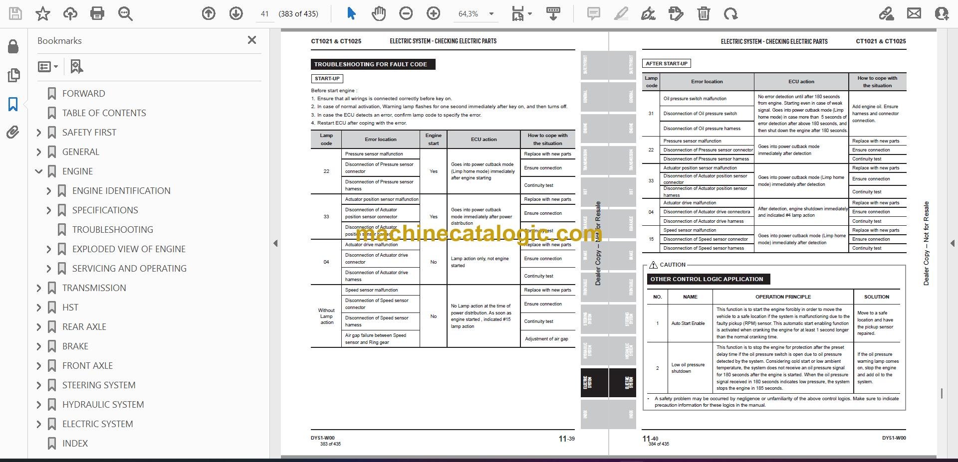
- TROUBLESHOOTING
- When the Engine Cannot Be Started
- When the System Is Not Charged
- When the System Is Not Preheated Manually (CT1021)
- When the System Is Not Preheated Automatically
- When The Cruise System Cannot Be Operated (OPTIONAL)
- When The Head Lamp Cannot Be Operated
- Tachometer Operation With The Engine Running
- Fuel Gauge Operation
- Temperature Gauge Operation
- Hour Meter Operation
- EXPLODED VIEW OF ELECTRIC SYSTEM
- Engine Electrical System
- Transmission Electrical System
- Chassis Electrical System
- Cruise (Optional)
- Wire Harness
- Light
- Working Lamp
- INDEX
Bobcat Software
Bobcat PDF Manuals


