$ 0
0
$ 0
0

Bobcat E35 Excavator Service Manual (SN B3WZ11001-B3WZ99999)

Format: PDF (Printable Document)

File Language: English

File Pages: 993

File Size: 35.89 MB (Speed Download Link)

Brand: Bobcat

Model: E35 Excavator

Book No: 7311307

Serial No: SN B3WZ11001-B3WZ99999

Type of Document: Service Manual

Categories: ,

$ 45

Share:

Bobcat E35 Excavator Service Manual (SN B3WZ11001-B3WZ99999)

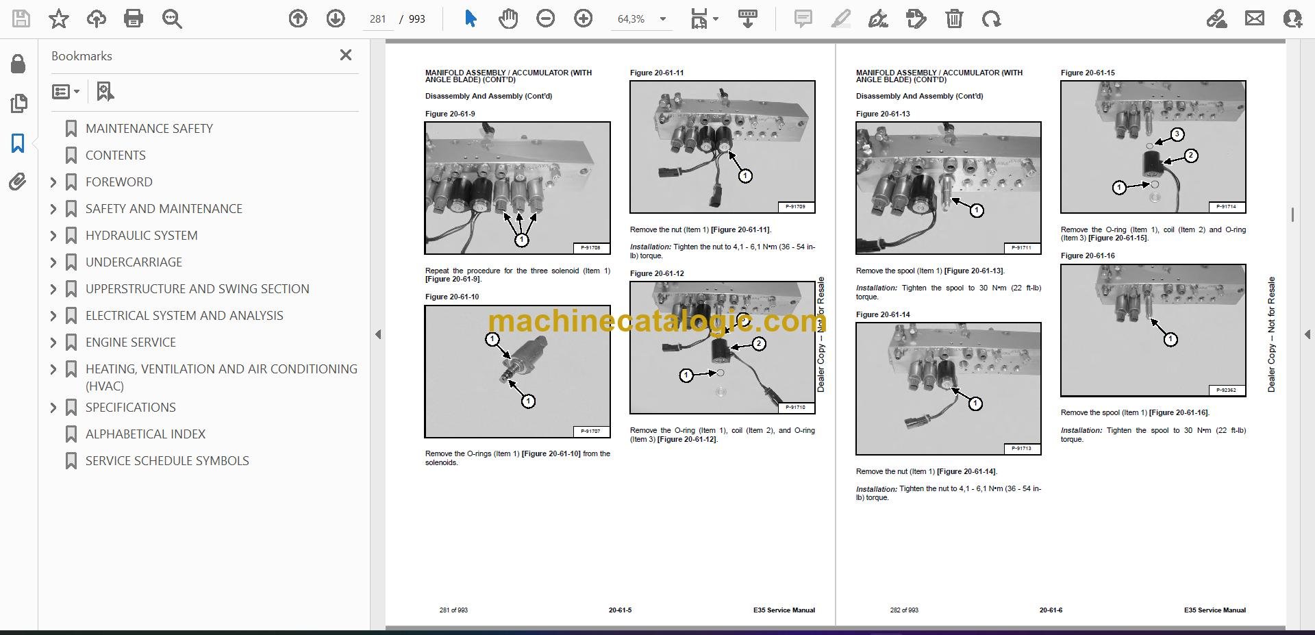
A Bobcat E35 is a tight-space mini excavator you haul to trench, set lines, dig footings, or clean up in backyards where a big machine won't fit. The service manual is what I grab in the truck when I need specs and step-by-step procedures, not just basic controls. People use it when they're chasing hydraulic or electrical problems, doing engine work, or tearing into swing and travel components. If you're past warranty and want to fix it yourself without guessing, this is the kind of manual you want.

What this manual helps you do

  • Diagnose hydraulic issues, check pressures, and trace leaks in the E35's implement and travel circuits
  • Troubleshoot electrical faults using wiring diagrams and step sequences instead of random parts swapping
  • Follow teardown and reassembly procedures for cylinders, drive motors, swing components, and major linkages
  • Adjust and verify settings on controls, pilot lines, and safety interlocks after repairs
  • Replace and set up engine-side components, cooling parts, and fuel system pieces on the E35

Who this is for

This is for an E35 owner-operator, small contractor, rental fleet, or shop mechanic who works on Bobcat compact excavators and wants real repair info. If you only need to know how to run the machine or daily checks, you want the operator's handbook instead, not this service manual.

FAQ

Q: Is this a searchable PDF and can I read the wiring diagrams clearly?

A: These manuals are usually delivered as searchable PDFs, and the wiring diagrams are laid out to zoom in on a laptop or tablet in the field.

Q: How do I know if it covers my exact E35?

A: If your E35 serial number falls between B3WZ11001 and B3WZ99999, this is the correct manual for your machine variant.

Q: Is this the right document if I'm doing real repairs, not just maintenance?

A: Yes, this is the workshop-level service manual, meant for diagnostics and repairs, not just basic maintenance schedules.

Bottom line, if your E35 serial number is in that B3WZ11001-B3WZ99999 range and you're actually turning wrenches on it, this is the manual you want.

📘 Show Index

Table of Contents:

  • MAINTENANCE SAFETY
  • CONTENTS
  • FOREWORD
    • FOREWORD
    • SAFETY INSTRUCTIONS
    • FIRE PREVENTION
      • Maintenance
      • Operation
      • Electrical
      • Hydraulic System
      • Fueling
      • Starting
      • Spark Arrester Exhaust System
      • Welding And Grinding
      • Fire Extinguishers
    • SERIAL NUMBER LOCATIONS
      • Excavator Serial Number
      • Engine Serial Number
    • DELIVERY REPORT
    • EXCAVATOR IDENTIFICATION
  • SAFETY AND MAINTENANCE
    • LIFTING AND BLOCKING THE EXCAVATOR
      • Procedure
    • LIFTING THE EXCAVATOR
      • Procedure
    • OPERATOR CAB (ROPS / TOPS)
      • Description
      • Cab Door
      • Front Window
      • Front Wiper
      • Window Washer Reservoir
      • Right Side Window
    • OPERATOR CANOPY (ROPS / TOPS)
      • Description
    • TRANSPORTING THE EXCAVATOR ON A TRAILER
      • Loading And Unloading
      • Fastening
    • TAILGATE
      • Opening And Closing
      • Adjusting The Latch
    • RIGHT SIDE COVER
      • Opening And Closing
    • SERVICE SCHEDULE
      • Maintenance Intervals
    • AIR CLEANER SERVICE
      • Daily Check
      • Replacing The Filters
    • CAB FILTERS
      • Cleaning And Maintenance
    • ENGINE COOLING SYSTEM
      • Cleaning
      • Checking Level
      • Removing And Replacing Coolant
    • FUEL SYSTEM
      • Fuel Specifications
      • Biodiesel Blend Fuel
      • Filling The Fuel Tank
      • Fuel Filters
      • Removing Air From The Fuel System
      • Draining The Fuel Tank
    • ENGINE LUBRICATION SYSTEM
      • Checking And Adding Engine Oil
      • Engine Oil Chart
      • Removing And Replacing Oil And Filter
    • HYDRAULIC SYSTEM
      • Checking And Adding Hydraulic Fluid
      • Hydraulic / Hydrostatic Fluid Chart
      • Removing And Replacing Hydraulic Filters
      • Removing And Replacing Hydraulic Fluid
    • LUBRICATING THE EXCAVATOR
      • Lubrication Locations
    • PIVOT PINS
      • Inspection And Maintenance
    • TRAVEL MOTOR
      • Checking And Adding Oil
      • Removing And Replacing Oil
    • EMERGENCY EXIT
      • Right Side Rear Window
      • Front Window
    • SEAT BELT
      • Inspection And Maintenance
    • CONTROL CONSOLE LOCKOUTS
      • Inspection And Maintenance
    • TOWING THE EXCAVATOR
      • Procedure
    • REMOTE START TOOL KIT – MEL1563
      • Remote Start Tool Kit – MEL1563
      • Service Tool Harness Control – MEL1565
      • Service Tool Harness Communicator – MEL1566
    • REMOTE START TOOL (SERVICE TOOL) KIT – 7217666
      • Description
      • Remote Start Tool (Service Tool) – 7022042
      • Excavator Service Tool Harness – 6689747
      • Computer Service Tool Harness – 6689746
  • HYDRAULIC SYSTEM
    • HYDRAULIC / HYDROSTATIC SCHEMATICS
    • HYDRAULIC SYSTEM INFORMATION
      • Glossary Of Hydraulic / Hydrostatic Symbols
      • Troubleshooting The Hydraulic Circuit
      • Troubleshooting The Cylinder Circuit
      • Troubleshooting The Swing (Upperstructure Slew) Circuit
      • Troubleshooting The Travel Circuit
    • CYLINDER (BOOM)
      • Testing
      • Removal And Installation
      • Parts Identification
      • Disassembly
      • Assembly
    • CYLINDER (ARM)
      • Testing
      • Removal And Installation
      • Parts Identification
      • Disassembly
      • Assembly
    • CYLINDER (BOOM SWING)
      • Testing
      • Removal And Installation
      • Parts Identification
      • Disassembly
      • Assembly
    • CYLINDER (BUCKET)
      • Testing
      • Removal And Installation
      • Parts Identification
      • Disassembly
      • Assembly
    • CYLINDER (BLADE)
      • Testing
      • Removal And Installation
      • Parts Identification
      • Disassembly
      • Assembly
    • CYLINDER (CLAMP)
      • Testing
      • Removal And Installation
      • Parts Identification
      • Disassembly
      • Assembly
    • CYLINDER (ANGLE BLADE)
      • Testing
      • Removal And Installation
      • Parts Identification
      • Disassembly
      • Assembly
    • CYLINDER (EXTENDABLE ARM)
      • Testing
      • Parts Identification
      • Disassembly
      • Assembly
    • VALVE (MAIN RELIEF)
      • Description
    • VALVE (PORT RELIEF)
      • Testing And Adjusting Port Relief Valve Pressure
    • VALVE (CROSS PORT RELIEF)
      • Testing
      • Removal And Installation
      • Disassembly And Assembly
    • VALVE (PILOT PRESSURE RELIEF)
      • Testing And Adjusting The Pilot Pressure Relief Valve
    • HYDRAULIC CONTROL VALVE
      • Description
      • Removal And Installation
      • Parts Identification
      • Disassembly
      • Assembly
      • Inlet Valve Section Disassembly And Assembly
      • Boom Swing Valve Section Disassembly And Assembly
      • Slew Valve Section Disassembly And Assembly
      • Blade Valve Section Disassembly And Assembly
      • Right And Left Travel Valve Section Disassembly And Assembly
      • Boom Valve Section Disassembly And Assembly
      • Auxiliary, Arm, Bucket And Angle Blade Valve Section Disassembly And Assembly
      • Outlet Valve Section Disassembly And Assembly
    • HYDRAULIC PUMP
      • Hydraulic Pump Work Sheet
      • Pump Testing
      • Description
      • Removal And Installation
      • Coupler Removal And Installation
      • Hydraulic Pump Startup
      • Gear Pump Disassembly And Assembly
      • Piston Pump Parts Identification
      • Piston Pump Disassembly And Assembly
    • MANIFOLD ASSEMBLY / ACCUMULATOR (WITHOUT ANGLE BLADE)
      • Description
      • Removal And Installation
      • Parts Identification
      • Disassembly And Assembly
    • MANIFOLD ASSEMBLY / ACCUMULATOR (WITH ANGLE BLADE)
      • Description
      • Removal And Installation
      • Parts Identification
      • Disassembly And Assembly
    • TRAVEL MOTOR
      • Description
      • Removal And Installation
      • Parts Identification Hydraulic Motor
      • Parts Identification Gear Reduction Hub
      • Disassembly
      • Assembly
    • SWIVEL JOINT (LATER MODELS)
      • Removal And Installation
      • Parts Identification Angle Blade Swivel
      • Parts Identification Straight Blade Swivel
      • Disassembly And Assembly
    • SWIVEL JOINT (EARLIER MODELS)
      • Removal And Installation
      • Parts Identification Angle Blade Swivel
      • Parts Identification Straight Blade Swivel
      • Disassembly And Assembly
    • SWING MOTOR
      • Removal And Installation
      • Parts Identification
      • Disassembly And Assembly
    • SWING MOTOR (DRIVE CARRIER)
      • Removal And Installation
      • Parts Identification
      • Disassembly And Assembly
    • CONTROL PATTERN SELECTOR VALVE
      • Removal And Installation
      • Parts Identification
      • Disassembly And Assembly
    • RIGHT CONTROL LEVER (JOYSTICK)
      • Testing
      • Handle Removal And Installation
      • Joystick Assembly Removal And Installation
      • Parts Identification
      • Disassembly
      • Assembly
    • LEFT CONTROL LEVER (JOYSTICK)
      • Testing
      • Handle Removal And Installation
      • Joystick Assembly Removal And Installation
      • Parts Identification
      • Disassembly
      • Assembly
    • HYDRAULIC FILTER MOUNT
      • Removal And Installation
    • HYDRAULIC RESERVOIR
      • Removal And Installation
    • OIL COOLER
      • Removal And Installation
    • DIRECT TO TANK VALVE
      • Removal And Installation
    • BLADE CONTROL LEVER
      • Handle Removal And Installation
      • Removal And Installation
      • Parts Identification
      • Disassembly And Assembly
    • CASE DRAIN FILTER MOUNT
      • Removal And Installation
    • TRAVEL CONTROL VALVE
      • Removal And Installation
      • Parts Identification
      • Disassembly And Assembly
    • REMOVING AIR FROM THE HYDRAULIC SYSTEM
      • Procedure
    • HYDRAULIC X-CHANGE MANIFOLD (EARLIER MODELS)
      • Removal And Installation
      • Parts Identification
      • Disassembly And Assembly
    • HYDRAULIC X-CHANGE MANIFOLD (LATER MODELS)
      • Removal And Installation
      • Parts Identification
      • Disassembly And Assembly
    • SECONDARY AUXILIARY VALVE
      • Removal And Installation
      • Parts Identification
      • Disassembly And Assembly
    • VALVE (BOOM LOCK)
      • Removal And Installation
    • VALVE (ARM LOCK)
      • Removal And Installation
  • UNDERCARRIAGE
    • BLADE
      • Removal And Installation
    • BLADE (ANGLE)
      • Removal And Installation
      • Cutting Edge Removal And Installation
    • TRACK UNDERCARRIAGE COMPONENTS (RUBBER TRACK)
      • Description
      • Track Lug Height
      • Checking Tension
      • Adjusting Tension
      • Removal And Installation
      • Idler Removal And Installation
      • Idler Parts Identification
      • Idler Disassembly
      • Idler Assembly
      • Track Tensioner Removal And Installation
      • Track Tensioner Parts Identification
      • Track Tensioner Disassembly And Assembly
      • Roller Removal And Installation
      • Sprocket Removal And Installation
    • TRACK UNDERCARRIAGE COMPONENTS (STEEL TRACK)
      • Description
      • Checking Tension
      • Adjusting Tension
      • Track Removal And Installation
      • Idler Removal And Installation
      • Idler Parts Identification
      • Idler Disassembly
      • Idler Assembly
      • Track Tensioner Removal And Installation
      • Track Tensioner Cylinder Parts Identification
      • Track Tensioner Disassembly And Assembly
      • Roller Removal And Installation
      • Sprocket Removal And Installation
      • Guide Plate Removal And Installation
    • TRACK MAINTENANCE
      • Track Damage Identification
    • SWING CIRCLE GEAR
      • Swing Bearing Removal
      • Swing Bearing Installation
  • UPPERSTRUCTURE AND SWING SECTION
    • UPPERSTRUCTURE
      • Removal
      • Installation
    • ROPS CANOPY
      • Removal And Installation
    • CAB
      • Removal And Installation
      • Door Removal And Installation
      • Front Window Removal And Installation
      • Front Window Disassembly And Assembly
      • Front Window Adjustment
      • Glass Removal
      • Glass Installation
    • SEAT
      • Removal And Installation
    • RIGHT CONSOLE
      • Console Cover Removal And Installation
    • LEFT CONSOLE
      • Lower Console Cover Removal And Installation
      • Upper Console Cover Removal And Installation
      • Compression Spring Removal And Installation
      • Lock Lever Removal And Installation
      • Console Removal And Installation
    • LEFT UPPERSTRUCTURE COVER
      • Removal And Installation
    • RIGHT UPPERSTRUCTURE COVER
      • Removal And Installation
    • COUNTERWEIGHT
      • Removal And Installation
      • Add On Counterweight Removal And Installation
    • TRAVEL LEVERS AND PEDALS
      • Removal And Installation
      • Disassembly And Assembly
    • FLOOR MAT
      • Removal And Installation
    • FUEL TANK
      • Removal And Installation
      • Fuel Tank Fitting Removal And Installation
    • HORN
      • Removal And Installation
    • SWING FRAME
      • Removal And Installation
      • Boom Swing Frame Hose Routing
      • Bushing Removal
      • Bushing Installation
    • BOOM
      • Removal And Installation
    • ARM (STANDARD AND LONG)
      • Removal And Installation
      • Arm To Boom Bushing Removal And Installation
      • Arm To Bucket And Bucket Link Bushing Removal And Installation
    • ARM (EXTENDABLE)
      • Removal And Installation
      • Arm To Boom Bushing Removal And Installation
      • Arm To Bucket Bushing Removal And Installation
      • Disassembly And Assembly
      • Shimming Procedure
    • BUCKET
      • Bucket Teeth Removal And Installation
      • Bucket Side Cutting Edge Removal And Installation
    • CLAMP
      • Removal And Installation
    • TAILGATE
      • Removal And Installation
      • Disassembly And Assembly
    • X-CHANGE
      • Removal And Installation
      • Disassembly
      • Assembly
    • X-CHANGE (HYDRAULIC) (EARLIER MODELS)
      • Removal And Installation
      • Parts Identification
      • Disassembly
      • Assembly
    • X-CHANGE (HYDRAULIC) (LATER MODELS)
      • Removal And Installation
      • Parts Identification
      • Disassembly
      • Assembly
      • Expansion Plug Installation
    • QUICK COUPLER (KLAC™ SYSTEM)
      • Troubleshooting
      • Daily Inspection
      • Removal And Installation
      • Parts Identification
      • Disassembly
      • Assembly
    • QUICK COUPLER (LEHNHOFF® SYSTEM)
      • Troubleshooting
      • Daily Inspection
      • Removal (MS03 And MS08)
      • Installation (MS03 And MS08)
      • Parts Identification (MS03)
      • Disassembly And Assembly (MS03)
      • Parts Identification (MS08)
      • Disassembly (MS08)
      • Assembly (MS08)
    • QUICK COUPLER (PIN GRABBER)
      • Troubleshooting
      • Daily Inspection
      • Removal And Installation
      • Parts Identification
      • Disassembly And Assembly
    • RIGHT SIDE COVER
      • Removal And Installation
      • Latch Removal And Installation
    • LEFT SIDE COVER
      • Removal And Installation
    • TOOL BOX
      • Removal And Installation
  • ELECTRICAL SYSTEM AND ANALYSIS
    • ELECTRICAL SCHEMATICS
    • ELECTRICAL SYSTEM INFORMATION
      • Troubleshooting Chart
      • Description
      • Fuse And Relay Location / Identification
    • BATTERY
      • Servicing
      • Maintaining Battery Charge Level
      • Battery Service During Machine Storage
      • Battery Testing
      • Battery Charging
      • Removal And Installation
      • Using A Booster Battery (Jump Starting)
    • ALTERNATOR
      • Belt Adjustment
      • Belt Replacement
      • Charging System Inspection
      • Alternator Voltage Testing
      • Low Voltage Testing
      • High Voltage Testing
      • Removal And Installation
      • Parts Identification
    • STARTER
      • Testing
      • Removal And Installation
      • Parts Identification
    • LIGHTS
      • Removal And Installation
      • Boom Light Removal And Installation
      • Boom Light Bulb Replacement
    • MAGNETIC LOCKOUT SENSOR
      • Removal And Installation
    • FUEL LEVEL SENDER
      • Removal And Installation
      • Testing
    • DIAGNOSTIC SERVICE CODES
      • Viewing Service Codes
      • Service Codes List
    • CONTROL PANEL SETUP
      • Panel Setup (Deluxe Instrument Panel)
      • Password Setup (Keyless Start Panel)
      • Password Setup (Deluxe Instrument Panel)
      • Maintenance Clock
    • INSTRUMENT PANEL
      • Removal And Installation
    • CONTROLLER
      • Description
      • Auxiliary Controller Removal And Installation
      • Gateway Controller Removal And Installation
    • KEY SWITCH
      • Removal And Installation
    • WIPER MOTOR
      • Removal And Installation
    • MOTION ALARM SYSTEM
      • Description
      • Inspecting
      • Adjusting Switch Position
    • SERVICE PC (LAPTOP COMPUTER)
      • Connecting The Remote Start Tool
      • Connecting Remote Start Tool (Service Tool)
    • SHUT-OFF SWITCH
      • Description
      • Removal And Installation
    • TRAVEL MOTOR AUTO-SHIFT
      • Auto-Shift Drive System (If Equipped)
      • Troubleshooting
    • ENGINE SPEED CONTROL
      • Removal And Installation
    • AUTO IDLE PRESSURE SENSOR
      • Description
      • Removal And Installation
    • BOBCAT MACHINE IQ WIRELESS COMMUNICATIONS
      • Description
      • Controller Removal And Installation
      • Antenna Removal And Installation
      • Procedure
  • ENGINE SERVICE
    • ENGINE INFORMATION
      • Description
      • Specifications
      • Sensor Location
      • Torque Values
      • Troubleshooting
      • Engine Removal And Installation
      • Compression – Testing
      • Injector Signal – Testing
    • DIESEL OXIDATION CATALYST (DOC)
      • Removal And Installation
    • AIR CLEANER
      • Housing Removal And Installation
    • ENGINE COOLING SYSTEM
      • Radiator Removal And Installation
      • Fan Removal And Installation
      • Water Pump Removal And Installation
      • Thermostat Housing Removal And Installation
      • Testing The Thermostat
    • FUEL SYSTEM
      • Description
      • Transfer Pump / High Pressure Pump Removal And Installation
      • Fuel Cooler Removal And Installation
      • Fuel Bypass Valve Removal And Installation
      • Fuel Recirculation Valve Removal and Installation
      • Fuel Injector Removal And Installation
      • Injector Coding
      • Removing Air From The Fuel System
    • LUBRICATION SYSTEM
      • Description
      • Oil Pan Removal And Installation
      • Oil Pump Removal And Installation
      • Oil Pump Relief Valve Description
      • Oil Pump Relief Valve Removal And Installation
      • Oil Cooler Removal And Installation
      • Oil Filter Head Removal And Installation
      • Oil Cooler Bypass Description
      • Oil Cooler Bypass Removal And Installation
    • CYLINDER HEAD
      • Glow Plugs Testing
      • Glow Plug Removal And Installation
      • Valve Clearance Adjustment
      • Cylinder Head Removal And Installation
      • Cylinder Head Disassembly And Assembly
      • Cylinder Head Inspection
      • Cylinder Head Top Clearance
      • Valve Step Height
      • Valve Stem Height
      • Valve Guide
      • Valve
      • Valve Spring
      • Rocker Arm Shaft Disassembly And Assembly
      • Rocker Arm Shaft Inspection
      • Push Rod Inspection
    • CRANKSHAFT AND PISTONS
      • Piston And Connecting Rod Removal And Installation
      • Piston And Connecting Rod Inspection
      • Crankshaft Removal And Installation
      • Cylinder Block Inspection
      • Crankshaft Inspection
      • Connecting Rod Inspection
      • Engine Component Class
    • CAMSHAFT
      • Removal And Installation
      • Inspecting
    • GEARCASE
      • Gearcase Cover Removal And Installation
      • Gear Backlash
      • Gear Timing
      • Idle Gear Removal And Installation
      • Idle Gear Inspection
    • TURBOCHARGER
      • Description
      • Removal And Installation
      • Inspection
    • FLYWHEEL AND HOUSING
      • Hydraulic Pump Coupler Removal And Installation
      • Flywheel Removal And Installation
      • Ring Gear Removal And Installation
    • EXHAUST GAS RECIRCULATION (EGR) SYSTEM
      • Valve Removal And Installation
      • Cooler Removal And Installation
    • INTERCOOLER
      • Description
      • Removal And Installation
  • HEATING, VENTILATION AND AIR CONDITIONING (HVAC)
    • AIR CONDITIONING SYSTEM FLOW
      • Description
      • Chart
      • Components
      • Safety Equipment
    • REGULAR MAINTENANCE
      • Cab Filters
      • Air Conditioning Compressor Belt Adjustment
      • Air Conditioning Compressor Belt Replacement
      • Condenser
      • Air Conditioning Lubrication
      • Evaporator / Heater Coil
      • Air Conditioning Service Chart
    • TROUBLESHOOTING
      • Blower Motor Does Not Operate
      • Blower Motor Operates Normally, But Air Flow Is Insufficient
      • Insufficient Cooling Although Air Flow And Compressor Operation Are Normal
      • The Compressor Operates Improperly Or Not At All
      • Gauge Pressure Related Troubleshooting
      • Temperature / Pressure Chart
      • Poor A/C Performance
      • HVAC Repair And Leaks
      • Electrical System
      • Engine Coolant Bypassing The Heater Valve
    • SYSTEM CHARGING AND RECLAMATION
      • Refrigerant Identification
      • Reclamation And Charging With Recovery / Charging Unit
    • COMPRESSOR
      • Removal And Installation
      • Oil
      • Oil Check
    • CONDENSER
      • Removal And Installation
    • RECEIVER / DRIER
      • Receiver / Drier Removal And Installation
      • Pressure Switch Removal And Installation
    • EVAPORATOR / HEATER UNIT
      • Removal And Installation
    • THERMOSTAT
      • Description
      • Removal And Installation
    • EXPANSION VALVE
      • Removal And Installation
    • EVAPORATOR COIL
      • Removal And Installation
    • HEATER COIL
      • Removal And Installation
    • BLOWER FAN
      • Removal And Installation
    • HEATER VALVE
      • Removal And Installation
    • HVAC DUCT
      • Removal And Installation
    • AUTO HVAC
      • Description
      • ATM Removal And Installation
      • ATM Diagnostic Codes
      • Blower Fan Drive Assembly Removal And Installation
      • De-Icing Sensor Removal And Installation
      • Inside And After Coil Sensor Testing
  • SPECIFICATIONS
    • EXCAVATOR SPECIFICATIONS
      • Machine Dimensions
      • Machine Dimensions – Standard Arm
      • Machine Dimensions – Long Arm
      • Machine Dimensions – Extendable Arm
      • Machine Dimensions – Angle Blade
      • Rated Lift Capacity – Standard Arm
      • Rated Lift Capacity – Standard Arm With Additional Counterweight
      • Rated Lift Capacity – Long Arm
      • Rated Lift Capacity – Extendable Arm
      • Performance
      • Engine
      • Controls
      • Hydraulic System
      • Hydraulic Cylinders
      • Hydraulic Cycle Times
      • Drive System
      • Slew System
      • Undercarriage
      • Electrical
      • Capacities
      • Tracks
      • Ground Pressure
    • TECHNICAL SERVICE GUIDE SPECIFICATIONS
      • Engine
      • Engine Torques
      • Cooling System
      • Excavator Torques
    • TORQUE SPECIFICATION FOR BOLTS
      • Torque For General SAE Bolts
      • Torque For General Metric Bolts
    • HYDRAULIC CONNECTION SPECIFICATIONS
      • O-ring Face Seal Connection
      • Straight Thread O-ring Fitting
      • Tubelines And Hoses
      • Flare Fitting
      • O-ring Flare Fitting
      • Port Seal Fitting
      • Push To Connect Fittings
    • HYDRAULIC FLUID SPECIFICATIONS
      • Specifications
    • CONVERSIONS
      • Decimal And Millimeter Equivalent Chart
      • U.S. To Metric Conversion Chart
    • SERVICE TOOLS REQUIRED
      • Remote Start Tools
      • Hydraulic Tools
      • Engine Tools
      • Electrical Tools
      • General Tools
      • HVAC Tools
  • ALPHABETICAL INDEX
  • SERVICE SCHEDULE SYMBOLS

Bobcat Software

Bobcat PDF Manuals

Related Manuals

0
    0
    Your Cart
    Your cart is emptyReturn to Shop