The S530 is a skid-steer loader in the mid-size class, the kind you see loading trucks, running augers, forks, and buckets on construction sites and farms. People grab this service manual when the machine is out of warranty and they want Cat/Deere-level repair info on a Bobcat. In my shop, this is what I'd use when I'm chasing a hydraulic issue, rebuilding a drive motor, or sorting out an electrical fault. It's the workshop book, not the "how to run the machine" booklet.
What this manual helps you do
- Diagnose hydraulic and hydrostatic issues, then check pressures and flows against Bobcat specs
- Trace and repair electrical and wiring problems using proper diagrams for the S530 in this serial range
- Follow step-by-step teardown and reassembly for major components like drive motors, cylinders, and axles
- Replace and adjust mechanical linkages, Bob-Tach, controls, and loader arms to factory procedures
- Verify engine-related service work, like fuel, cooling, and basic top-end work, with correct sequences and checks
Who this is for
This is for an S530 owner-operator, small contractor, rental fleet, or shop mechanic who is actually wrenching on the machine. If you only want operating tips, safety info, or basic maintenance intervals, you want the operator's handbook instead, not this service manual.
FAQ
Q: Is this a searchable PDF and are the wiring diagrams readable?
A: These manuals are usually supplied as searchable PDFs, and the wiring diagrams are laid out so you can zoom in and follow circuits clearly on-screen.
Q: Will this cover my S530 if my serial number is in the ALR811001-ALR899999 range?
A: Yes, this manual is matched to S530 loaders in that exact serial number block.
Q: Is this the right document if I'm rebuilding or diagnosing, not just changing oil?
A: Yes, this is the workshop-level service manual meant for real repair work and diagnostics.
Bottom line: If your S530 falls in serial range ALR811001-ALR899999 and you're doing your own repairs, this is the right manual. If you only need how to operate it, skip this and get the operator's book.
📘 Show Index
Table of Contents:
- MAINTENANCE SAFETY
- CONTENTS
- FOREWORD
- FOREWORD
- SAFETY INSTRUCTIONS
- FIRE PREVENTION
- Maintenance
- Operation
- Electrical
- Hydraulic System
- Fueling
- Starting
- Spark Arrester Exhaust System
- Welding And Grinding
- Fire Extinguishers
- SERIAL NUMBER LOCATIONS
- Loader Serial Number
- Engine Serial Number
- DELIVERY REPORT
- LOADER IDENTIFICATION
- SAFETY AND MAINTENANCE
- LIFTING AND BLOCKING THE LOADER
- LIFT ARM SUPPORT DEVICE
- Description
- Installing
- Removing
- OPERATOR CAB
- Description
- Cab Door Sensor
- Raising
- Lowering
- Special Applications Kit
- Special Applications Kit Inspection And Maintenance
- Forestry Door And Window Kit
- Forestry Door And Window Kit Inspection And Maintenance
- TRANSPORTING THE LOADER ON A TRAILER
- Loading And Unloading
- Fastening
- TOWING THE LOADER
- REMOTE START TOOL KIT – MEL1563
- Remote Start Tool – MEL1563
- Service Tool Harness Communicator – MEL1566
- Remote Start Procedure
- REMOTE START TOOL (SERVICE TOOL) KIT – 7217666
- Description
- Remote Start Tool (Service Tool) – 7022042
- Loader Service Tool Harness – 6689747
- Computer Service Tool Harness – 6689746
- Remote Start Procedure
- SERVICE SCHEDULE
- ENGINE AIR CLEANER
- ENGINE COOLING SYSTEM
- Maintenance Platform
- Cleaning
- Checking And Adding Coolant
- Removing And Replacing Coolant
- FUEL SYSTEM
- Fuel Specifications
- Biodiesel Blend Fuel
- Filling The Fuel Tank
- Fuel Filter
- Removing Air From The Fuel System
- ENGINE LUBRICATION SYSTEM
- Checking And Adding Engine Oil
- Engine Oil Chart
- Removing And Replacing Oil And Filter
- HYDRAULIC / HYDROSTATIC SYSTEM
- Checking And Adding Fluid
- Hydraulic / Hydrostatic Fluid Chart
- Removing And Replacing Hydraulic Fluid
- Removing And Replacing Hydraulic / Hydrostatic Filter
- Removing And Replacing Hydraulic Charge Filter
- Replacing Reservoir Breather Cap
- FINAL DRIVE TRANSMISSION (CHAINCASE)
- Checking And Adding Fluid
- Removing And Replacing Fluid
- BOB-TACH (HAND LEVER)
- Inspection And Maintenance
- BOB-TACH (POWER)
- Inspection And Maintenance
- LUBRICATING THE LOADER
- TIRE MAINTENANCE
- Wheel Nuts
- Rotating
- Mounting
- PIVOT PINS
- Inspection And Maintenance
- LOADER STORAGE AND RETURN TO SERVICE
- Storage
- Return To Service
- STOPPING THE ENGINE AND LEAVING THE LOADER
- EMERGENCY EXIT
- Rear Window Identification
- Rear Window Removal (Latches)
- Rear Window Removal (Rubber Cord)
- External Access (Rear Window With Latches)
- External Access (Rear Window With Rubber Cord)
- Front Door
- SEAT BELT
- Inspection And Maintenance
- HYDRAULIC SYSTEM
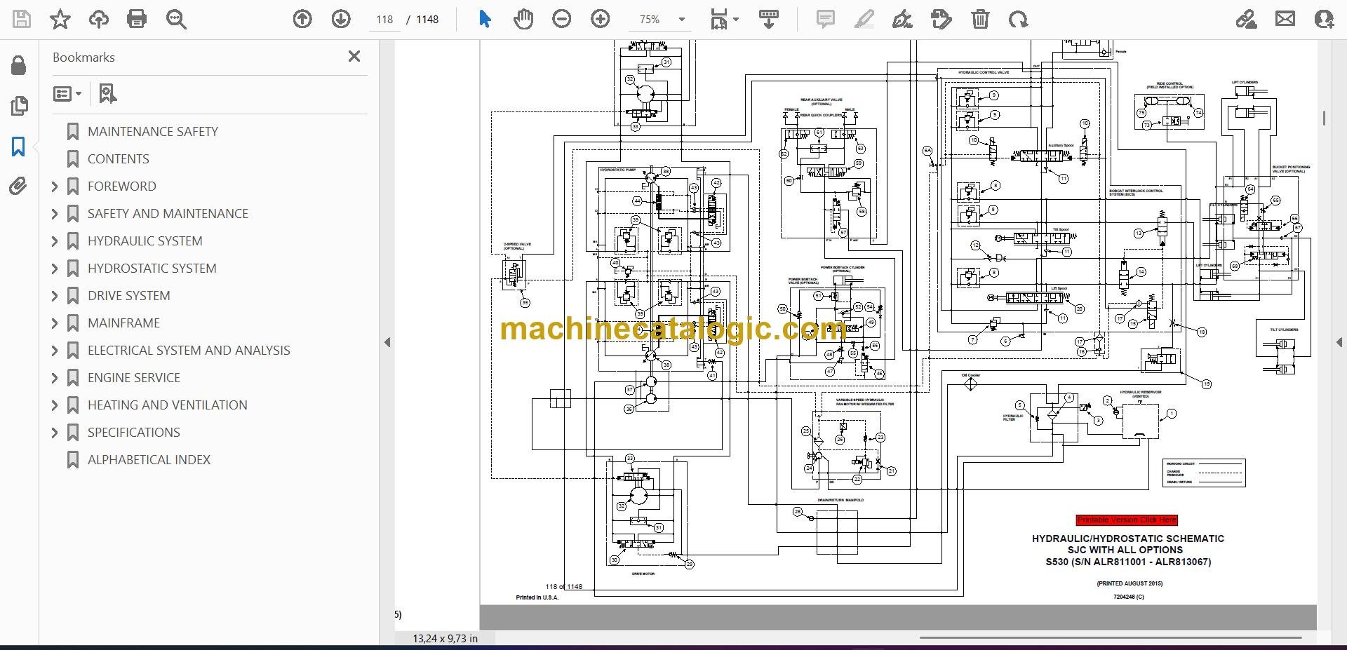
- HYDRAULIC / HYDROSTATIC SCHEMATICS
- HYDRAULIC SYSTEM INFORMATION
- Glossary Of Hydraulic / Hydrostatic Symbols
- Troubleshooting
- CYLINDER (LIFT)
- Testing
- Removal And Installation
- Parts Identification
- Disassembly
- Assembly
- CYLINDER (TILT)
- Testing
- Removal And Installation
- Base End Pivot Pin Removal And Installation
- Parts Identification
- Disassembly
- Assembly
- CYLINDER (LIFT) (B42T11022 & ABOVE)
- Testing
- Removal And Installation
- Parts Identification
- Disassembly
- Assembly
- CYLINDER (TILT) (B42T11022 & ABOVE)
- Testing
- Removal And Installation
- Base End Pivot Pin Removal And Installation
- Parts Identification
- Disassembly
- Assembly
- CYLINDER (BOB-TACH)
- Testing
- Removal And Installation
- Parts Identification
- Disassembly
- Assembly
- MAIN RELIEF VALVE
- Description
- Testing
- Adjusting
- Removal And Installation
- HYDRAULIC CONTROL VALVE (STANDARD)
- Description
- Removal And Installation
- Mount Bracket Removal And Installation
- Identification Chart
- Lift Load Check Valve Removal And Installation
- Load Check Valve Removal And Installation (Tilt And Auxiliary)
- Anti-Cavitation Valve Removal And Installation (Lift, Rod End)
- Port Relief / Anti-Cavitation Valve Removal And Installation (Lift, Base End)
- Port Relief / Anti-Cavitation Valve Removal And Installation (Tilt, Base End)
- Port Relief / Anti-Cavitation Valve Removal And Installation (Tilt, Rod End)
- Port Relief Valve Removal And Installation
- Plug Removal And Installation
- Rubber Boot Removal And Installation
- End Cap Block Removal And Installation
- Lift Spool And Detent Removal And Installation
- Tilt Spool Removal And Installation
- Auxiliary Spool Removal And Installation
- Auxiliary Solenoid Removal And Installation
- Solenoid Removal And Installation
- Lock Valve Removal And Installation
- Lift Arm Bypass Orifice Removal And Installation
- Main Relief Valve Removal And Installation
- Check Valve Removal And Installation
- HYDRAULIC CONTROL VALVE (ACS) OR (SJC)
- Description
- Removal And Installation
- Actuator Removal And Installation (In Loader)
- Actuator Removal And Installation (Out Of Loader)
- Identification Chart
- Mount Bracket Removal And Installation
- Lift Load Check Valve Removal And Installation
- Load Check Valve Removal And Installation (Tilt And Auxiliary)
- Anti-Cavitation Valve Removal And Installation (Lift, Rod End)
- Port Relief / Anti-Cavitation Valve Removal And Installation (Lift, Base End)
- Port Relief / Anti-Cavitation Valve Removal And Installation (Tilt, Base End)
- Port Relief / Anti-Cavitation Valve Removal And Installation (Tilt, Rod End)
- Port Relief Valve Removal And Installation
- Plug Removal And Installation
- End Cap Block Removal And Installation
- Lift Spool Removal And Installation
- Lift Spool Disassembly And Assembly
- Tilt Spool Removal And Installation
- Auxiliary Spool Removal And Installation
- Auxiliary Solenoid Removal And Installation
- Solenoid Removal And Installation
- Lock Valve Removal And Installation
- Lift Arm Bypass Orifice Removal And Installation
- Main Relief Valve Removal And Installation
- Check Valve Removal And Installation
- LIFT ARM BYPASS CONTROL VALVE
- Description
- Testing
- Removal And Installation
- Bracket Removal And Installation
- Disassembly And Assembly
- HYDRAULIC PUMP
- Description
- Pump Test At Quick Couplers
- Direct Pump Test (Standard Section)
- Direct Pump Test (Charge Section)
- Removal And Installation
- Hydraulic Pump Startup
- Parts Identification
- Disassembly And Assembly
- HYDRAULIC / HYDROSTATIC FILTERS
- Description
- Housing Removal And Installation
- HYDRAULIC FLUID RESERVOIR
- Description
- Removal And Installation
- Hydraulic Fluid Screen
- OIL COOLER
- BUCKET POSITION VALVE
- Description
- Solenoid Removal And Installation
- Solenoid Testing
- Removal And Installation
- Disassembly And Assembly
- REAR AUXILIARY DIVERTER VALVE
- Description
- Solenoid Testing
- Removal And Installation
- Disassembly And Assembly
- BOB-TACH (POWER) BLOCK (S/N ALR811001 – ALR813067)
- Description
- Removal And Installation
- Disassembly And Assembly
- BOB-TACH (POWER) BLOCK (S/N ALR813068 & ABOVE)
- Description
- Testing Relief Valve
- Removal And Installation
- Disassembly And Assembly
- FRONT AUXILIARY HYDRAULIC COUPLER BLOCK
- Description
- Removal And Installation
- Disassembly And Assembly (FFI/FI)
- Disassembly And Assembly (FFH/FH)
- AUTOMATIC RIDE CONTROL
- Description
- Removal And Installation
- Checking The Pressure In The Accumulator
- Adding Nitrogen To The Accumulator
- HYDROSTATIC SYSTEM
- HYDROSTATIC SYSTEM INFORMATION
- Description
- Troubleshooting
- HYDROSTATIC DRIVE MOTOR
- Description
- Removal And Installation
- Parts Identification
- Disassembly And Assembly
- HYDROSTATIC DRIVE MOTOR (TWO-SPEED)
- Description
- Removal And Installation (Left Side)
- Removal And Installation (Right Side)
- Parts Identification
- Disassembly
- Assembly
- HYDROSTATIC MOTOR CARRIER
- Description
- Shaft Seal Removal And Installation
- Removal And Installation
- Parts Identification
- Disassembly
- Assembly
- HYDROSTATIC MOTOR CARRIER (TWO-SPEED)
- Description
- Shaft Seal Removal And Installation
- Removal And Installation
- Parts Identification
- Disassembly
- Assembly
- CHARGE PRESSURE
- Description
- Testing
- Adjusting
- Sender Removal And Installation (Earlier Models)
- Sender Removal And Installation (Later Models)
- HYDROSTATIC PUMP
- Description
- Removal And Installation
- Hydrostatic Pump Startup
- Replenishing / High Pressure Relief Valve Removal And Installation
- Parts Identification (Left Half)
- Parts Identification (Right Half)
- Disassembly
- Assembly
- HYDROSTATIC PUMP (SJC)
- Description
- Hydraulic Controller Removal And Installation
- Removal And Installation
- Hydrostatic Pump Startup
- Parts Identification
- High Pressure Relief And Bypass Valve
- Charge Relief Valve
- Disassembly And Assembly
- Mechanical Neutral Adjustment
- Hydraulic Controller Neutral Adjustment
- DRIVE BELT
- Belt Adjustment
- Stop Adjustment
- Belt Replacement
- Tensioner Removal And Installation (Earlier Models)
- Tensioner Disassembly And Assembly
- Tensioner Pulley Removal And Installation (Later Models)
- Tensioner Pulley Disassembly And Assembly
- TWO-SPEED
- Valve Block Removal And Installation
- Valve Block Disassembly And Assembly
- DRAIN MANIFOLD
- Description
- Drain Manifold Removal And Installation
- DRIVE SYSTEM
- BRAKE
- Description
- Disc Removal And Installation
- DRIVE COMPONENTS
- Description
- Axle Seal Removal And Installation
- Axle, Sprocket And Bearings Removal And Installation
- Chain Removal And Installation
- CHAINCASE
- Description
- Front Cover Removal And Installation
- Center Cover Removal And Installation
- Rear Cover Removal And Installation
- MAINFRAME
- SEAT BAR
- Description
- Removal And Installation
- Disassembly And Assembly
- Compression Spring Disassembly And Assembly
- OPERATOR CAB
- Gas Spring Removal And Installation
- Gas Spring Bracket Disassembly And Assembly
- Removal And Installation
- OPERATOR SEAT
- Removal And Installation
- Seat Belt Removal And Installation (Retractable)
- Seat Belt And Bracket Removal And Installation (Standard)
- Seat Belt Bracket Removal And Installation
- OPERATOR SEAT (SUSPENSION)
- Removal And Installation
- Slide Rail Removal And Installation
- Seat Belt Removal And Installation
- Lower Cushion Removal
- Lower Cushion Installation
- Back Cushion Removal And Installation
- Shock Removal And Installation
- 3-Point Seat Belt Removal And Installation
- BOB-TACH (HAND LEVER)
- Description
- Removal And Installation
- Lever And Wedge Disassembly And Assembly
- Pivot Pin Bushing And Seal Removal And Installation
- BOB-TACH (POWER)
- Description
- Removal And Installation
- Lever And Wedge Disassembly And Assembly
- Pivot Pin Bushing And Seal Removal And Installation
- LIFT ARMS
- Stabilizer Bar Removal And Installation
- Link Removal And Installation
- Removal And Installation
- REAR GRILLE
- Removing
- Installing
- Shield Removal And Installation
- REAR DOOR (TAILGATE)
- Removal And Installation
- Striker Removal And Installation
- Striker Disassembly And Assembly
- Striker Adjusting
- Latch Removal And Installation
- FUEL TANK
- Removal And Installation
- Fuel Level Sender Removal And Installation
- Fuel Fill Screen Removal And Installation
- CONTROL PEDALS AND LINKAGES
- Description
- Pedal Removal And Installation
- Linkage Removal And Installation
- Pedal (Adjusting)
- Floor Pan Removal And Installation
- CONTROL PEDALS AND LINKAGES (ACS)
- Description
- Pedal Removal And Installation
- Linkage Removal And Installation
- Pedal (Adjusting)
- Floor Pan Removal And Installation
- CONTROL PANEL
- Description
- Removal And Installation
- Disassembly And Assembly
- Linkage Removal And Installation
- Pintle Arm Disassembly And Assembly
- Linkage Neutral (Adjusting)
- Linkage Travel (Adjusting)
- Shock Removal And Installation
- CONTROL PANEL (SJC)
- Description
- Removal And Installation
- CONTROL HANDLE / LEVER
- Description
- Lever Removal And Installation
- Boot Removal And Installation
- CONTROL HANDLE / LEVER (ACS)
- Description
- Handle Sensor Removal And Installation
- Handle Removal And Installation
- Handle Disassembly And Assembly
- Lever Removal And Installation
- Boot Removal And Installation
- CONTROL HANDLE / LEVER (SJC)
- Description
- Joystick Testing
- Joystick Removal And Installation
- ACCESS PANEL (INSIDE)
- Removal And Installation (Left)
- Removal And Installation (Right)
- ACCESS PANEL (INSIDE) (SJC)
- Removal And Installation (Left)
- Removal And Installation (Right)
- WINDOW (REAR)
- Rear Window Identification
- Rear Window Removal (Latches)
- Rear Window Removal (Rubber Cord)
- External Access (Rear Window With Latches)
- External Access (Rear Window With Rubber Cord)
- Disassembly And Assembly (Latches)
- WINDOW (TOP)
- WINDOW (SIDE)
- CAB DOOR
- Description
- Removal And Installation
- Disassembly And Assembly
- Aligning
- Adjusting
- Checking Operation
- ARMREST
- Description
- Removal And Installation
- Disassembly And Assembly
- LEFT SIDE LOWER PANEL
- Removal And Installation
- Disassembly And Assembly
- RIGHT SIDE LOWER PANEL
- Removal And Installation
- Disassembly And Assembly
- HEADLINER
- FAN DUCT PANELS
- ELECTRICAL SYSTEM AND ANALYSIS
- ELECTRICAL SCHEMATICS
- ELECTRICAL SYSTEM INFORMATION
- Glossary Of Electrical Symbols
- Standard Cab Harness Connectors
- Deluxe Cab Harness Connectors
- Mainframe Harness Connectors – Manual Controls
- Mainframe Harness Connectors – SJC
- Engine Harness Connectors
- Description
- Troubleshooting
- Fuse And Relay Location / Identification
- Solenoid Testing
- BATTERY
- Removal And Installation
- Servicing
- Using A Booster Battery (Jump Starting)
- ALTERNATOR
- Belt Adjustment
- Belt Replacement
- Charging System Inspection
- Alternator Voltage Testing
- Low Voltage Testing
- High Voltage Testing
- Removal And Installation
- Parts Identification
- STARTER
- Testing
- Removal And Installation
- Parts Identification
- INSTRUMENT PANELS
- Left Panel
- Display Screen
- Right Panel (Standard Key Panel)
- Right Panel (Keyless Start Panel)
- Right Panel (Deluxe Instrumentation Panel)
- Left Switch Panel
- Right Switch Panel
- Left Side Lower Panel
- Right Side Lower Panel
- Left Panel Removal And Installation
- Right Panel (Standard Key Panel) Removal And Installation
- Right Panel (Keyless Start Panel) Removal And Installation
- Right Panel (Deluxe Instrumentation Panel) Removal And Installation
- Key Switch Disassembly And Assembly
- Alarm Disassembly And Assembly
- Left Switch Panel Removal And Installation
- Right Switch Panel Removal And Installation
- LIGHTS
- Front Removal And Installation
- Rear Removal And Installation
- Cab Light Removal And Installation (Earlier Models)
- Cab Light Removal And Installation (Later Models)
- BOBCAT CONTROLLERS (GATEWAY AND AUXILIARY)
- Description
- Connector Identification
- Removal And Installation
- BOBCAT CONTROLLER (ACS)
- Description
- Connector And Wire Identification
- Removal And Installation
- BOBCAT CONTROLLER (SJC) (DRIVE)
- Description
- Connector Identification
- Removal And Installation
- ENGINE CONTROL UNIT (ECU)
- Description
- Cleaning
- Removal And Installation
- DIAGNOSTIC SERVICE CODES
- Viewing Service Codes
- Service Codes List
- BOBCAT INTERLOCK CONTROL SYSTEM (BICS™)
- Description
- Inspecting The BICS™ (Engine STOPPED – Key ON)
- Inspecting Deactivation Of The Auxiliary Hydraulics System (Engine STOPPED – Key ON)
- Inspecting The Seat Bar Sensor (Engine RUNNING)
- Inspecting The Traction Lock And Parking Brake (Engine RUNNING)
- Inspecting The Lift Arm Bypass Control
- Inspecting Deactivation Of Lift And Tilt Functions (ACS And SJC)
- Troubleshooting
- SEAT BAR SENSOR
- Description
- Troubleshooting
- Testing
- Removal
- Installation
- Bobcat Interlock Control System (BICS™) Circuit Test
- TRACTION LOCK
- Description
- Troubleshooting
- Inspecting
- CONTROL SYSTEM (ACS)
- Description
- Troubleshooting
- Handle Sensor Connector Disassembly And Assembly
- Switch Handle Removal
- Switch Handle Installation
- Actuator Connector Disassembly And Assembly
- Handle Lock Solenoid Removal And Installation
- Handle Lock Solenoid Disassembly And Assembly
- Foot Sensor Removal And Installation
- Foot Sensor Disassembly And Assembly
- Foot Sensor Lock Solenoid Removal And Installation
- ELECTRICAL / HYDRAULIC CONTROLS
- Identification Chart
- Description
- Identification Chart ACD Group 0
- Identification Chart ACD Group 1
- Identification Chart ACD Group 2
- Identification Chart ACD Group 3
- ELECTRICAL / HYDRAULIC CONTROLS (ACS)
- Identification Chart
- Description
- Identification Chart ACD Group 0
- Identification Chart ACD Group 1
- Identification Chart ACD Group 2
- Identification Chart ACD Group 3
- ELECTRICAL / HYDRAULIC CONTROLS (SJC)
- Identification Chart
- Description
- Identification Chart ACD Group 0
- Identification Chart ACD Group 1
- Identification Chart ACD Group 2
- Identification Chart ACD Group 3
- SERVICE PC (LAPTOP COMPUTER)
- Connecting Remote Start Tool
- Connecting Remote Start Tool (Service Tool)
- CALIBRATION
- Description
- Actuator Testing
- Lift And Tilt Calibration (SJC)
- Hydrostatic Pump Calibration (SJC)
- Lift And Tilt Calibration (ACS)
- STEERING DRIFT COMPENSATION (OPERATOR MODE)
- STEERING DRIFT COMPENSATION (SERVICE MODE)
- CONTROL PANEL SETUP
- Right Panel Setup (Deluxe Instrumentation Panel)
- PASSWORD SETUP (DELUXE INSTRUMENTATION PANEL)
- Password Description
- Changing The Owner Password
- Changing The User Passwords
- Password Lockout Feature
- PASSWORD SETUP (KEYLESS START PANEL)
- Password Description
- Changing The Owner Password
- Password Lockout Feature
- MAINTENANCE CLOCK
- BACK-UP ALARM SYSTEM
- Description
- Inspecting
- Adjusting Switch Position
- Troubleshooting (Standard And ACS)
- Troubleshooting (Joystick)
- Alarm Removal And Installation
- Switch Removal And Installation
- FRONT HORN
- Removal And Installation
- Troubleshooting
- Troubleshooting (Joystick)
- ENGINE SPEED CONTROL (HAND)
- ENGINE SPEED CONTROL (FOOT)
- Removal And Installation
- Disassembly And Assembly
- Foot Throttle Calibration
- CAMSHAFT AND CRANKSHAFT POSITION SENSOR
- ENGINE SERVICE
- ENGINE INFORMATION
- Description
- Specifications
- Sensor Location
- Torque Values
- Troubleshooting
- Engine Removal And Installation
- Engine Mount Replacement
- Compression – Testing
- Injector Signal – Testing
- Injector Signal – Testing (In-Line)
- DIESEL OXIDATION CATALYST (DOC)
- AIR CLEANER
- Housing Removal And Installation
- ENGINE COOLING SYSTEM (EARLIER MODELS)
- Radiator / Oil Cooler Removal And Installation
- Hydraulic Fan Description
- Fan Duct Removal And Installation
- Hydraulic Fan Motor Assembly Removal And Installation
- Hydraulic Fan Motor Removal And Installation
- Hydraulic Fan Motor Disassembly And Assembly
- Blower Housing Removal And Installation
- Water Pump Removal And Installation
- Thermostat Housing Removal And Installation
- Testing The Thermostat
- ENGINE COOLING SYSTEM (LATER MODELS)
- Radiator / Oil Cooler Removal And Installation
- Hydraulic Fan Description
- Reversible Hydraulic Fan Description
- Fan Duct Removal And Installation
- Hydraulic Fan Motor Assembly Removal And Installation
- Hydraulic Fan Motor Removal And Installation
- Hydraulic Fan Motor Disassembly And Assembly
- Hydraulic Fan Motor Assembly Removal And Installation
- Blower Housing Removal And Installation
- Water Pump Removal And Installation
- Thermostat Housing Removal And Installation
- Testing The Thermostat
- LUBRICATION SYSTEM
- Description
- Oil Pan Removal And Installation
- Oil Pump Removal And Installation
- Oil Pump Relief Valve Description
- Oil Pump Relief Valve Removal And Installation
- Oil Cooler Removal And Installation
- Oil Filter Head Removal And Installation
- Oil Cooler Bypass Description
- Oil Cooler Bypass Removal And Installation
- FUEL SYSTEM
- Description
- Transfer Pump / High Pressure Pump Removal And Installation
- Fuel Temperature Sensor Removal And Installation
- Fuel Cooler Removal And Installation
- Fuel Bypass Valve Removal And Installation
- Fuel Recirculation Valve Removal And Installation
- Fuel Rail Assembly Removal And Installation
- Fuel Injector Removal And Installation
- Injector Coding
- Removing Air From The Fuel System
- CYLINDER HEAD
- Glow Plugs Testing
- Glow Plug Removal And Installation
- Valve Clearance Adjustment
- Cylinder Head Removal And Installation
- Cylinder Head Disassembly And Assembly
- Cylinder Head Inspection
- Cylinder Head Top Clearance
- Valve Step Height
- Valve Stem Height
- Valve Guide
- Valve
- Valve Spring
- Rocker Arm Shaft Disassembly And Assembly
- Rocker Arm Shaft Inspection
- Push Rod Inspection
- CRANKSHAFT AND PISTONS
- Piston And Connecting Rod Removal And Installation
- Piston And Connecting Rod Inspection
- Crankshaft Removal And Installation
- Cylinder Block Inspection
- Crankshaft Inspection
- Connecting Rod Inspection
- Engine Component Class
- CAMSHAFT
- Removal And Installation
- Inspecting
- GEARCASE
- Gearcase Cover Removal And Installation
- Gear Backlash
- Gear Timing
- Idle Gear Removal And Installation
- Idle Gear Inspection
- TURBOCHARGER
- Description
- Removal And Installation
- Inspection
- FLYWHEEL AND HOUSING
- Flywheel Removal And Installation
- Ring Gear Removal And Installation
- Housing Removal And Installation
- EXHAUST GAS RECIRCULATION (EGR) SYSTEM
- Description
- Removal And Installation
- Disassembly And Assembly
- HEATING AND VENTILATION
- REGULAR MAINTENANCE
- TROUBLESHOOTING
- Blower Motor Does Not Operate
- Blower Motor Operates Normally, But Air Flow Is Insufficient
- Troubleshooting Tree
- Electrical System
- Engine Coolant Bypassing The Heater Valve
- Heater Valve Not Opening Or Closing
- HEATER UNIT
- HEATER COIL
- BLOWER FAN
- Removal And Installation
- Disassembly And Assembly
- HEATER VALVE
- EVAPORATOR / HEATER COVER
- SPECIFICATIONS
- (S530) LOADER SPECIFICATIONS
- Machine Dimensions
- Performance
- Engine
- Drive System
- Controls
- Hydraulic System
- Electrical System
- Capacities
- Tires
- TECHINCAL SERVICE GUIDE SPECIFICATIONS
- Engine
- Engine Torques
- Cooling System
- Loader Torques
- Hydraulic / Hydrostatic System
- Fuel Consumption
- TORQUE SPECIFICATIONS FOR BOLTS
- Torque For General SAE Bolts
- Torque For General Metric Bolts
- HYDRAULIC CONNECTION SPECIFICATIONS
- Straight Thread O-ring Fitting
- Flare Fitting
- Tubelines And Hoses
- HYDRAULIC / HYDROSTATIC FLUID SPECIFICATIONS
- CONVERSIONS
- Decimal And Millimeter Equivalent Chart
- U.S. To Metric Conversion Chart
- SERVICE TOOLS REQUIRED
- Remote Start Tools
- Hydraulic Tools
- Mainframe And Drive Tools
- Electrical Tools
- Engine Tools
- HVAC Tools
- ALPHABETICAL INDEX
Bobcat Software
Bobcat PDF Manuals


