$ 0
0
$ 0
0

Bobcat T35140 VersaHANDLER® TTC, Telescopic Handler Service Manual (SN B51511001-B51599999)

Format: PDF (Printable Document)

File Language: English

File Pages: 814

File Size: 27.54 MB (Speed Download Link)

Brand: Bobcat

Model: T35140 VersaHANDLER® TTC, Telescopic Handler

Book No: 7400387

Serial No: SN B51511001-B51599999

Type of Document: Service Manual

Categories: ,

$ 45

Share:

Bobcat T35140 VersaHANDLER® TTC, Telescopic Handler Service Manual (SN B51511001-B51599999)

On a real site the T35140 is your reach machine: feeding block to masons, setting trusses, loading trucks, doing forklift work where a skid or CTL just can't reach. The people who grab this service manual are the ones actually fixing it when it stops lifting, steering, or starting. They're chasing hydraulic faults, electrical gremlins, or doing big repairs that go way past what the operator's handbook covers.

What this manual helps you do

  • Diagnose hydraulic and boom issues, trace oil flow, and check pressures on the telescopic and stabilizer circuits
  • Troubleshoot hydrostatic drive problems, follow test steps, and verify charge and drive performance like you would on Cat or Deere telehandlers
  • Trace and repair wiring faults, using readable schematics to sort CAN lines, safety interlocks, and sensor power/grounds
  • Rebuild or replace major components, like cylinders, drive components, and attachment couplers, with teardown and reassembly procedures
  • Set and verify adjustments on brakes, steering, boom wear pads, and safety switches after parts replacement

Who this is for

This is for shop mechanics, field techs, rental fleets, and owner-operators who actually wrench on a Bobcat T35140 with serial numbers in the B51511001-B51599999 range. If you only want basic controls, daily checks, or load charts, you want the operator's handbook instead, not this manual.

FAQ

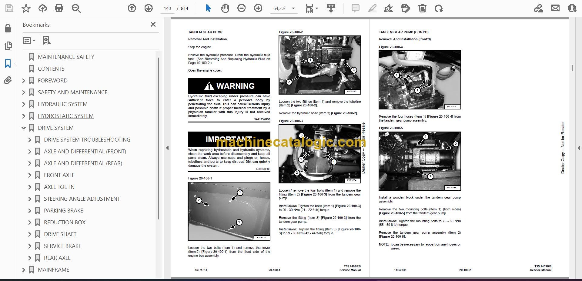
Q: Is this a searchable PDF, and can you read the wiring diagrams clearly?

A: These manuals are usually scanned or native PDFs that you can search, and the wiring pages are made to be zoomed so you can read pin numbers and wire colors.

Q: How do I know if it fits my exact machine?

A: Check your T35140 serial tag. If it falls between B51511001 and B51599999, this is the right service manual family.

Q: Is this the right manual if I'm only doing basic maintenance?

A: If you're doing oil changes and simple checks, it's overkill. If you're diagnosing faults or tearing into systems, this is the one you want.

Bottom line: If your T35140's serial number is in that B51511* to B51599* band and you're doing real repair work, this is the right Bobcat service manual.

📘 Show Index

Table of Contents:

  • MAINTENANCE SAFETY
  • CONTENTS
  • FOREWORD
    • FOREWORD
    • SAFETY INSTRUCTIONS
      • Safe Operation Is The Operator’s Responsibility
      • Safe Operation Needs A Qualified Operator
      • Avoid Silica Dust
      • Dismantling And Disposal
    • FIRE PREVENTION
      • Maintenance
      • Operation
      • Electrical
      • Hydraulic System
      • Fueling
      • Starting
      • Welding And Grinding
      • Fire Extinguishers
    • PUBLICATIONS AND TRAINING RESOURCES
    • SERIAL NUMBER LOCATION
      • Telescopic Handler Serial Number
      • Engine Serial Number
      • Other Serial Numbers
    • DELIVERY REPORT
    • BOBCAT TELESCOPIC HANDLER IDENTIFICATION
  • SAFETY AND MAINTENANCE
    • LIFTING AND BLOCKING THE TELESCOPIC HANDLER
      • Procedure
    • OPERATOR CAB
      • Description
      • Cab Door
      • Cab Door Window
      • Rear Cab Window
      • Cab Light
    • TRANSPORTING THE TELESCOPIC HANDLER ON A TRAILER
      • Loading And Unloading
      • Fastening
    • TOWING THE TELESCOPIC HANDLER
      • Procedure
    • SERVICE SCHEDULE
      • Maintenance Intervals
    • AIR CLEANER SERVICE
      • Replacing Filter Elements
      • Cleaning The Dust Extractor
    • COOLING SYSTEM
      • Cleaning
      • Checking Level
      • Removing And Replacing The Coolant
    • FUEL SYSTEM
      • Fuel Specifications
      • Filling The Fuel Tank
      • Replacing The Fuel Tank Breather
      • Fuel Pre-Filter
      • Fuel Filter
      • Removing Air From The Fuel System
    • ENGINE LUBRICATION SYSTEM
      • Checking And Adding Engine Oil
      • Engine Oil Chart
      • Removing And Replacing Oil And Filter
    • HYDRAULIC / HYDROSTATIC SYSTEM
      • Checking And Adding Fluid
      • Removing And Replacing Hydraulic Fluid
      • Removing And Replacing Hydraulic / Hydrostatic Filters
      • Fill / Breather Cap
    • AXLES (FRONT AND REAR)
      • Checking And Adding Oil (Planetary Carrier)
      • Removing And Replacing Oil (Planetary Carrier)
      • Checking And Adding Oil (Rear Differential)
      • Removing And Replacing Oil (Rear Differential)
      • Checking And Adding Oil (Front Differential)
      • Removing And Replacing Oil (Front Differential)
      • Checking And Adding Oil (Reduction Box)
      • Removing And Replacing Oil (Reduction Box)
    • LUBRICATING THE TELESCOPIC HANDLER
      • Lubrication Locations
      • Front Pads Lubrication
      • Rear Pads Lubrication
    • ATTACHMENT CARRIER
      • Inspection And Maintenance
    • TIRE MAINTENANCE
      • Wheel Nuts
      • Rotating
      • Wheel Replacement
      • Mounting
      • Pressure
    • APPROVED BOOM STOP
      • Installing The Approved Boom Stop
      • Removing The Approved Boom Stop
    • ENGINE COVER
      • Opening And Closing
    • CHAIN CHECKING AND ADJUSTING PROCEDURE
      • Checking / Adjustment Procedure
      • Extension / Retraction Chain Wear Check
    • STOPPING THE ENGINE AND LEAVING THE TELESCOPIC HANDLER
      • Procedure
    • EMERGENCY EXIT
      • Rear Window
    • TELESCOPIC HANDLER STORAGE AND RETURN TO SERVICE
      • Storage
      • Return To Service
    • LIFTING THE TELESCOPIC HANDLER
      • Procedure
    • REMOTE START TOOL (SERVICE TOOL) KIT – 6987761
      • Remote Start Tool (Service Tool) – 7022042
      • Telescopic Handler Service Tool Harness – 6689747
      • Computer Service Tool Harness – 6689746
      • Remote Start Procedure
  • HYDRAULIC SYSTEM
    • HYDRAULIC / HYDROSTATIC SCHEMATICS
    • HYDRAULIC SYSTEM INFORMATION
      • Glossary Of Hydraulic / Hydrostatic Symbols
      • Troubleshooting Chart
      • Tightening Procedures
      • Test Coupler Location
    • BOOM CYLINDER
      • Removal And Installation
      • Parts Identification
      • Disassembly
      • Assembly
    • SELF LEVELING (COMPENSATION) CYLINDER
      • Removal And Installation
      • Parts Identification
      • Disassembly
      • Assembly
    • EXTENSION CYLINDER
      • Cylinder Group Removal And Installation
      • Parts Identification
      • Disassembly
      • Assembly
    • TILT CYLINDER
      • Removal And Installation
      • Parts Identification
      • Disassembly
      • Assembly
    • STEERING CYLINDER (FRONT / REAR)
      • Removal
      • Installation
      • Disassembly
      • Assembly
    • BRAKES BLOCK
      • Removing And Installing The Standard Brakes Block
      • Removing And Installing The Italian Brakes Block
      • Removing And Installing The German Brakes Block
    • ACCUMULATORS
      • Accumulators Pressure Relief
      • Removing And Installing The Park / Service Brake Accumulator
      • Removing And Installing The Boom Lift Valve Accumulator
    • SERVICE BRAKE VALVE
      • Removal And Installation
    • TANDEM GEAR PUMP
      • Removal And Installation
      • Parts Identification
      • Disassembly And Assembly
    • TANDEM GEAR PUMP (TESTING)
      • Fan Gear Pump Direct Test
      • Steering And Valve Gear Pump Direct Test
    • FAN MOTOR
      • Description
      • Removal And Installation
      • Parts Identification (Single Speed Version) (Standard)
      • Disassembly And Assembly (Single Speed Version) (Standard)
      • Parts Identification (Variable Speed Version) (Optional)
      • Disassembly And Assembly (Variable Speed Version) (Optional)
    • FAN MOTOR (VARIABLE SPEED FAN MOTOR TESTING)
      • Description
      • Testing
    • HYDRAULIC FLUID TANK
      • Removal And Installation
    • STEERING UNIT
      • Removal And Installation
    • STEERING UNIT (TESTING)
      • Testing The Steering Unit Main Relief Valve
    • MAIN VALVE
      • Troubleshooting Chart (Solenoid Valves)
      • Valve Section Troubleshooting
      • Troubleshooting Chart (Main Valve)
      • Removal And Installation
      • Section Removal
      • Section Disassembly And Assembly
      • Inlet-Outlet Valve Section Disassembly And Assembly
      • End Housing Disassembly And Assembly
    • MAIN RELIEF VALVE
      • Testing
      • Adjusting
    • PORT RELIEF VALVES
      • Removal And Installation
    • DIVERTER VALVE
      • Removal And Installation
    • SELF LEVELING VALVE
      • Removal And Installation
    • AUXILIARY HYDRAULIC FLOW
      • Testing The Auxiliary Hydraulic Flow
    • STABILIZER / FRAME LEVELING VALVE
      • Removal
      • Installation
      • Disassembly
      • Solenoid Testing
      • Assembly
    • STABILIZER CYLINDER
      • Removal
      • Parts Identification
      • Disassembly
      • Assembly
      • Installation
  • HYDROSTATIC SYSTEM
    • HYDROSTATIC SYSTEM INFORMATION
      • Troubleshooting Chart
      • Test Coupler Location
    • OIL COOLER
      • Description
    • HYDROSTATIC DRIVE MOTOR
      • Removal And Installation
      • Parts Identification
      • Disassembly
      • Inspection
      • Assembly
    • HYDROSTATIC PUMP
      • Removal And Installation
      • Parts Identification
      • Shaft Disassembly
      • Relief Valves Disassembly And Assembly
      • Charge Pump Disassembly
      • Piston Pump Disassembly
      • Solenoid Block Disassembly
      • Inspection
      • Piston Pump Assembly
      • Charge Pump Assembly
      • Solenoid Block Assembly
      • Shaft Assembly
    • CHARGE PRESSURE
      • Description
      • Testing And Adjusting
    • MULTI-FUNCTION VALVES
      • Description
      • Testing
    • PRESSURE COMPENSATION OVERRIDE VALVE (PCOR)
      • Description
      • Testing And Adjusting
  • DRIVE SYSTEM
    • DRIVE SYSTEM TROUBLESHOOTING
      • Chart
    • AXLE AND DIFFERENTIAL (FRONT)
      • Description
      • Planetary Carrier And Drive Axle Parts Identification
      • Planetary Carrier Disassembly
      • Steering Knuckle Parts Identification
      • Steering Knuckle Disassembly
      • Drive Axle Disassembly
      • Brake Group Parts Identification
      • Brake Group Disassembly
      • Differential And Pinion Group Parts Identification
      • Differential Disassembly
      • Pinion Group Disassembly
      • Pinion Group Assembly
      • Differential Assembly
      • Brake Group Assembly
      • Drive Axle Assembly
      • Steering Knuckle Assembly
      • Planetary Carrier Assembly
    • AXLE AND DIFFERENTIAL (REAR)
      • Description
      • Planetary Carrier And Drive Axle Parts Identification
      • Planetary Carrier Disassembly
      • Steering Knuckle Parts Identification
      • Steering Knuckle Disassembly
      • Differential And Pinion Group Parts Identification
      • Differential Disassembly
      • Pinion Group Disassembly
      • Pinion Group Assembly
      • Differential Assembly
      • Steering Knuckle Assembly
      • Planetary Carrier Assembly
    • FRONT AXLE
      • Removal
      • Installation
      • Mounting Bolts Tightening Torque Check
    • AXLE TOE-IN
      • Adjustment
    • STEERING ANGLE ADJUSTMENT
      • Adjustment
    • PARKING BRAKE
      • Parking Brake Removal, Disassembly And Assembly
    • REDUCTION BOX
      • Removal And Installation
      • Parts Identification
      • Disassembly
      • Assembly
    • DRIVE SHAFT
      • Removal And Installation
    • SERVICE BRAKE
      • Description
      • Bleeding The Brake Circuit
    • REAR AXLE
      • Removal And Installation
  • MAINFRAME
    • OPERATOR CAB
      • Removal And Installation
    • OPERATOR SEAT
      • Removal And Installation
    • BOOM ASSEMBLY
      • Removal And Installation
    • BOOM TRAY
      • Removal And Installation
    • END BOOM
      • Removal
      • Installation
    • INTERMEDIATE BOOM
      • Removal
      • Installation
    • WEAR PADS (FRONT)
      • Boom Wear Pad Checking
      • Removal
      • Installation
    • WEAR PADS (REAR)
      • Boom Wear Pad Checking
      • Removal
      • Installation
    • ENGINE COVER
      • Gas Cylinder Removal And Installation
      • Removal And Installation
    • FUEL TANK
      • Removal And Installation
    • ATTACHMENT CARRIER (QUICK-TACH)
      • Removal And Installation
    • COUNTERWEIGHT
      • Removal And Installation
    • FENDER
      • Removal And Installation
    • STEERING COLUMN COVER
      • Removal And Installation
    • DASH COVER
      • Removal And Installation
    • JOYSTICK PANEL
      • Removal And Installation
    • STABILIZER FRAME
      • Removal
  • ELECTRICAL SYSTEM AND ANALYSIS
    • ELECTRICAL SCHEMATICS
    • ELECTRICAL SYSTEM INFORMATION
      • Glossary Of Electrical Symbols
      • Cab Harness Connectors
      • Mainframe Harness Connectors
      • Engine Bay Harness Connectors
      • Engine Harness Connectors
      • Troubleshooting Chart
      • Description
      • Fuses And Relay Location / Identification
    • BATTERY
      • Removing And Installing The Battery
      • Using A Booster Battery (Jump Starting)
    • ALTERNATOR
      • Belt Adjustment
      • Belt Checking
      • Belt Replacement
      • Removal And Installation
    • STARTER
      • Testing
      • Removal And Installation
    • LIGHTS
      • Rear Light Removal And Installation
      • Front Light Removal And Installation
      • Rear Work Light Removal And Installation
    • SIGNAL LEVER
      • Removal And Installation
    • DISPLAY
      • Removal And Installation
    • INSTRUMENT PANEL
      • Removal And Installation
    • BOOM ANGLE SENSOR
      • Removal And Installation
    • FRONT WIPER MOTOR
      • Removal And Installation
    • TOP WIPER MOTOR
      • Removal And Installation
    • REAR WIPER MOTOR
      • Removal And Installation
    • SERVICE BRAKE PEDAL ASSEMBLY
      • Removal And Installation
    • INCHING SENSOR
      • Removal And Installation
    • SERVICE PC (LAPTOP COMPUTER)
      • Connecting Remote Start Tool (Service Tool) – 6987761
    • FUEL LEVEL SENDER
      • Removal And Installation
    • JOYSTICK
      • Removal And Installation
    • LLMI / LLMC SYSTEM
      • System Components Identification
      • LLMS Removal
      • LLMS Installation
      • LLMC Removal And Installation
    • TRAVEL DIRECTION LEVER
      • Removal And Installation
    • CONTROLLERS
      • Description
      • Gateway Controller
      • Drive Controller
      • Work Group Controller
      • Display Controller
      • LLMI Controller
      • LLMC Controller
      • Engine Controller
    • MAINTENANCE CLOCK
      • Description
      • Setup
      • Reset
    • CALIBRATION
      • Calibrating The Hydrostatic Pump
      • Calibrating The Boom Angle Sensor
      • Calibrating The Lift Coils
      • Calibrating The Inching Sensor
      • Calibrating The Frame Leveling Sensor
      • Calibrating The LLMI / LLMC System
      • LLMC Calibration Test
      • LLMI / LLMC System Failure Reports
  • ENGINE SERVICE
    • ENGINE INFORMATION
      • Description
      • Tightening Torques For Main Parts
      • Sensor Location
      • Engine Specifications
      • Engine Serial Numbers
      • Torque Values
      • Troubleshooting
      • Removal And Installation
      • Disassembling The Engine
      • Assembling The Engine
    • ENGINE BAY ASSEMBLY
      • Removal And Installation
    • ENGINE SPEED CONTROL
      • Removal And Installation
    • EXHAUST PIPE
      • Removal And Installation
    • AIR CLEANER
      • Housing Removal And Installation
    • COOLING SYSTEM
      • General Information
      • Hydraulic Oil Cooler / Intercooler / Radiator Removal And Installation
      • Expansion Tank Removal And Installation
      • Removing The Coolant Pump
      • Installing The Coolant Pump
      • Removing The Thermostat
      • Installing The Thermostat
      • Checking The Thermostat
      • Cooling System Check
      • Cooling System Inspection
    • LUBRICATION SYSTEM
      • General Information
      • Troubleshooting
      • Removing The Oil Pump
      • Installing The Oil Pump
      • Checking The Oil Pump
      • Removing The Oil Suction Pipe
      • Installing The Oil Suction Pipe
      • Removing The Oil Filter Assembly
      • Installing The Oil Filter Assembly
      • Checking the Oil Filter Assembly
      • Removing The Oil Pan
      • Installing The Oil Pan
    • DIESEL PARTICULATE FILTER (DPF)
      • Removal And Installation
    • EXHAUST GAS RECIRCULATION (EGR) SYSTEM
      • General Information
    • EXHAUST GAS RECIRCULATION (EGR) SYSTEM (CONT’D)
      • Removing The EGR
      • Installing The EGR
    • TURBOCHARGER
      • General Information
      • Troubleshooting
      • Removing The Turbocharger
      • Installing The Turbocharger
      • Checking The Turbocharger
    • INTAKE / EXHAUST SYSTEM
      • Removing The Intake Manifold
      • Installing The Intake Manifold
      • Removing The Exhaust Manifold
      • Installing The Exhaust Manifold
      • Removing The Throttle (Inlet Pipe) And The Intake Stake
      • Installing The Throttle (Inlet Pipe) And The Intake Stake
    • FUEL SYSTEM
      • General Information
      • Removing The Fuel Return Hose
      • Installing The Fuel Return Hose
      • Removing The Injector
      • Installing The Injector
      • Checking The Injector
      • Removing The Common Rail
      • Installing The Common Rail
      • Checking the Common Rail
      • Removing The Fuel Injection Pump
      • Installing The Fuel Injection Pump
      • Removing The Fuel Injection Pump Drive Gear
      • Installing The Fuel Injection Pump Drive Gear
    • CYLINDER BLOCK / HEAD
      • Disassembling The Cylinder Block
      • Assembling The Cylinder Block
      • General Inspection Of Cylinder Block
      • Measurement Of Inside Diameter Of Main Bearing Bore
      • Measurement Of Inside Diameter Of Piston Bore
      • Measurement of Inside Diameter of Camshaft Bearing
      • Removing The Cylinder Head
      • Installing The Cylinder Head
      • Checking The Cylinder Head
      • Removing Valves
      • Installing Valves
      • Measurement of Inside Diameter of Valve Guide
      • Measurement Of Valve Stem End
      • Measurement Of Valve Step Height
      • Measurement Of Gap Between Piston And Valve
      • Checking The Valve Spring
      • Removing The Rocker Arms
      • Installing The Rocker Arms
      • Checking The Rocker Arms
      • Checking The Rocker Arm Shaft
      • Removing The Valve Tappets
      • Installing The Valve Tappets
      • Checking The Valve Tappets
      • Removing The Push Rods
      • Installing The Push Rods
      • Checking The Deflection Of The Push Rod
      • Removing The Camshaft
      • Removing The Camshaft Gear
      • Installing The Camshaft Gear
      • Installing The Camshaft
      • Measuring The Camshaft Journal O.D.
      • Measuring The Camshaft
      • Removing The Flywheel Housing
      • Installing The Flywheel Housing
      • Removing The Breather Hose
      • Installing The Breather Hose
      • Removing The Cylinder Head Cover
      • Installing The Cylinder Head Cover
      • Removing The Idle Gear
      • Installing The Idle Gear
      • Measuring The Outside Diameter Of The Idle Gear Shaft
      • Measuring The Inside Diameter Of The Idle Gear
      • Removing The Lifting Hooks
      • Installing The Lifting Hooks
      • Removing The Front Oil Seal Holder
      • Installing The Front Oil Seal Holder
    • ENGINE DRIVING SYSTEM
      • Removing The Crankshaft
      • Installing The Crankshaft
      • Measuring The Diameter Of The Crankshaft Main Journal
      • Measuring The Crankshaft Bearing Clearance
      • Measuring The Deflection Of The Crankshaft
      • Removing The Timing Wheel
      • Installing The Timing Wheel
      • Removing The Pistons
      • Disassembling The Pistons
      • Assembling The Pistons
      • Installing The Pistons
      • Measuring The Inside Diameter Of The Piston Pin Bore In Pistons
      • Measuring The Step Height Of The Piston Top Side
      • Measuring The Piston Ring End Gap
      • Measuring The Outside Diameter Of The Piston Pin
      • Disconnecting The Connecting Rod
      • Installing The Connecting Rod
      • Measuring The Inside Diameter Of The Connecting Rod Small End
      • Measuring The Inside Diameter Of The Connecting Rod Big End
      • Measuring The Connecting Rod Big End Clearance
      • Removing The Crankshaft Pulley
      • Installing The Crankshaft Pulley
    • ENGINE TIMING
      • General Description
      • Adjusting The Engine Timing
      • Checking The Gear Backlash
      • Checking The Axial Play Of Gears
  • HEATING, VENTILATION, AIR CONDITIONING (HVAC)
    • AIR CONDITIONING SYSTEM FLOW
      • Description
      • Chart
      • Components
      • Safety Equipment
    • REGULAR MAINTENANCE
      • Cab Filter
      • A/C System Water Condensate Rubber Valves
      • Belt Adjustment
      • Belt Replacement
      • Cleaning The Condenser
      • Air Conditioning Lubrication
      • Air Conditioning Service Chart
    • A/C SYSTEM TROUBLESHOOTING
      • Blower Motor Does Not Operate
      • Blower Motor Operates Normally, But Air Flow Is Insufficient
      • Insufficient Cooling Although Air Flow And Compressor Operation Are Normal
      • The Compressor Does Not Operate At All, Or Operates Improperly
      • Gauge Pressure Related Troubleshooting
      • Temperature / Pressure Chart
      • Poor A/C Performance
      • HVAC Repair And Leaks
      • Electrical System
    • SYSTEM CHARGING AND RECLAMATION
      • Reclamation And Charging With Recovery / Charging Unit
    • COMPRESSOR
      • Removal And Installation
      • Oil
      • Oil Check
      • Clutch Disassembly And Assembly
    • CONDENSER
      • Removal And Installation
    • RECEIVER / DRIER
      • Removal And Installation
    • PRESSURE SWITCH
      • Removal And Installation
    • EVAPORATOR / HEATER UNIT
      • Removal And Installation
    • THERMOSTAT
      • Description
      • Removal And Installation
    • EXPANSION VALVE
      • Removal And Installation
  • SPECIFICATIONS
    • T35.140SRB TELESCOPIC HANDLER SPECIFICATIONS
      • Machine Dimensions
      • Performance
      • Weights
      • Engine
      • Controls
      • Drive System
      • Traction
      • Steering
      • Brakes
      • Fluid Capacities
      • Hydraulic System
      • Electrical System
      • Temperature Range
      • Altitude
      • Instrument Panel
      • Environmental
    • VISIBILITY DIAGRAMS
      • Model T35.140SRB
    • LIFTING AND TIE-DOWN SPECIFICATIONS
      • Lifting
      • Tie-Down
    • MACHINE TORQUE SPECIFICATIONS
      • Axle
      • Boom
      • Reduction Box
      • Drive Motor
      • Engine
      • Hydraulic Pump
    • TORQUE SPECIFICATIONS FOR BOLTS
      • Torque For General SAE Bolts
      • Torque For General Metric Bolts
    • HYDRAULIC CONNECTION SPECIFICATIONS
      • Straight Thread O-ring Fitting
      • Tubelines And Hoses
      • Flare Fitting
      • O-ring Flare Fitting
      • Port Seal Fitting
    • HYDRAULIC / HYDROSTATIC FLUID SPECIFICATIONS
      • Specifications
    • CONVERSIONS
      • Decimal And Millimeter Equivalent Chart
      • U.S. To Metric Conversion Chart
    • SERVICE TOOLS REQUIRED
      • Remote Start Tools
      • Hydraulic Tools
      • Drive Tools
      • Electrical Tools
      • Special Drive Tools
  • ALPHABETICAL INDEX

Bobcat Software

Bobcat PDF Manuals

Related Manuals

0
    0
    Your Cart
    Your cart is emptyReturn to Shop