$ 0
0
$ 0
0

Bobcat TL360 VersaHANDLER® TTC, Telescopic Handler Service Manual (SN AN6H11001-AN6H99999)

Format: PDF (Printable Document)

File Language: English

File Pages: 782

File Size: 39.43 MB (Speed Download Link)

Brand: Bobcat

Model: TL360 VersaHANDLER® TTC, Telescopic Handler

Book No: 6990100

Serial No: SN AN6H11001-AN6H99999

Type of Document: Service Manual

Categories: ,

$ 45

Share:

Bobcat TL360 VersaHANDLER® TTC, Telescopic Handler Service Manual (SN AN6H11001-AN6H99999)

The TL360 VersaHANDLER is a telescopic handler that spends its life loading trucks, stacking pallets, and feeding material on farms and jobsites. The people who reach for this service manual are the ones actually keeping it moving: shop mechanics, field techs, and owners who do their own repairs. They need correct teardown order, hydraulic test points, and wiring logic so the machine is back on rent or back on the job instead of sitting dead in the yard.

What this manual helps you do

  • Diagnose hydraulic and hydrostatic problems, then check pressures and trace leaks on the TL360's boom, steering, and drive systems.
  • Follow step-by-step removal and installation for major components like the boom sections, axles, cylinders, and attachment coupler.
  • Troubleshoot electrical issues using wiring diagrams so you can chase down no-start, sensor, and lighting faults.
  • Rebuild and adjust key assemblies, including brake components, steering linkages, and drivetrain parts, with the right sequences and specs.
  • Verify adjustments after repair so the handler lifts, drives, and stabilizes the way the factory intended.

Who this is for

This is for anyone maintaining or repairing a Bobcat TL360 VersaHANDLER TTC in the AN6H11001 through AN6H99999 serial range, whether you're a small contractor, rental fleet shop, or owner-operator. If you only want basic controls, safety, and daily checks, you need the operator's handbook instead, not this service manual.

FAQ

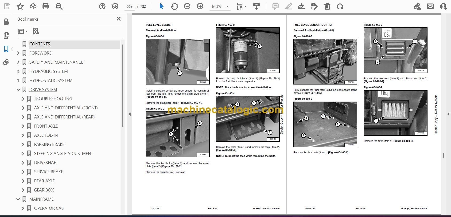
Q: Is this a searchable PDF, and can I read the wiring diagrams clearly?

A: These manuals are usually text searchable, and the wiring diagrams are laid out so you can zoom in and follow each circuit on a laptop or tablet.

Q: How do I know if it fits my exact machine?

A: Check your TL360 serial number plate. If it falls between AN6H11001 and AN6H99999, this is the correct service manual family for your machine.

Q: Is this what I need for real repairs, or just maintenance?

A: This is the workshop-level service manual, meant for diagnostics and repairs, not just routine greasing and fluid changes.

Bottom line: If you own or service a TL360 in that AN6H11001-AN6H99999 range and you're doing actual repairs, this is the right manual. If you just want to learn how to run the machine, skip it.

📘 Show Index

Table of Contents:

  • CONTENTS
  • FOREWORD
    • FOREWORD
    • SAFETY INSTRUCTIONS
      • Safe Operation Is The Operator’s Responsibility
      • Safe Operation Needs A Qualified Operator
      • Avoid Silica Dust
      • Dismantling And Disposal
    • FIRE PREVENTION
      • Maintenance
      • Operation
      • Electrical
      • Hydraulic System
      • Fueling
      • Starting
      • Welding And Grinding
      • Fire Extinguishers
    • SERIAL NUMBER LOCATION
      • Telescopic Handler Serial Number
      • Engine Serial Number
      • Other Serial Numbers
    • DELIVERY REPORT
    • BOBCAT TELESCOPIC HANDLER IDENTIFICATION
  • SAFETY AND MAINTENANCE
    • LIFTING AND BLOCKING THE TELESCOPIC HANDLER
      • Procedure
    • OPERATOR CAB
      • Description
      • Cab Door
      • Cab Door Window
      • Rear Cab Window
      • Cab Light
    • TRANSPORTING THE TELESCOPIC HANDLER ON A TRAILER
      • Loading And Unloading
      • Fastening
    • TOWING THE TELESCOPIC HANDLER
      • Procedure
    • SERVICE SCHEDULE
      • Maintenance Intervals
    • AIR CLEANER SERVICE
      • Replacing Filter Elements
    • ENGINE COOLING SYSTEM
      • Cleaning
      • Checking Level
      • Removing And Replacing The Coolant
    • FUEL SYSTEM
      • Fuel Specifications
      • Biodiesel Blend Fuel
      • Filling The Fuel Tank
      • Primary Fuel Filter (Pre-Filter)
      • Secondary Fuel Filter
      • Removing Air From The Fuel System
    • ENGINE LUBRICATION SYSTEM
      • Checking And Adding Engine Oil
      • Engine Oil Chart
      • Removing And Replacing Oil And Filter
    • HYDRAULIC / HYDROSTATIC SYSTEM
      • Checking And Adding Fluid
      • Hydraulic / Hydrostatic Fluid Chart
      • Removing And Replacing Hydraulic Fluid
      • Removing And Replacing Hydraulic / Hydrostatic Filter
      • Removing And Replacing Hydraulic Charge Filter
      • Fill / Breather Cap
    • AXLES (FRONT AND REAR)
      • Checking And Adding Oil (Planetary Carrier)
      • Removing And Replacing Oil (Planetary Carrier)
      • Checking And Adding Oil (Rear Differential)
      • Removing And Replacing Oil (Rear Differential)
      • Checking And Adding Oil (Front Differential)
      • Removing And Replacing Oil (Front Differential)
      • Checking And Adding Oil (Gear Box)
      • Removing And Replacing Oil (Gear Box)
    • LUBRICATING THE TELESCOPIC HANDLER
      • Lubrication Locations
    • ATTACHMENT CARRIER
      • Inspection And Maintenance
    • TIRE MAINTENANCE
      • Wheel Nuts
      • Rotating
      • Mounting
      • Pressure
    • APPROVED BOOM STOP
      • Installing The Approved Boom Stop
      • Removing The Approved Boom Stop
    • ENGINE COVER
      • Opening And Closing
    • STOPPING THE ENGINE AND LEAVING THE TELESCOPIC HANDLER
      • Procedure
    • EMERGENCY EXIT
      • Right Rear Window
    • TELESCOPIC HANDLER STORAGE AND RETURN TO SERVICE
      • Storage
      • Return To Service
    • LIFTING THE TELESCOPIC HANDLER
      • Procedure
    • REMOTE START TOOL (SERVICE TOOL) KIT – MEL1563
      • Remote Start Tool – MEL1563
      • Service Tool Harness Control – MEL1565
      • Service Tool Harness Communicator – MEL1566
    • REMOTE START TOOL (SERVICE TOOL) KIT – 7003031
      • Remote Start Tool (Service Tool) – 7003030
      • Telescopic Handler Service Tool Harness – 6689747
      • Computer Service Tool Harness – 6689746
      • Remote Start Procedure
  • HYDRAULIC SYSTEM
    • HYDRAULIC/HYDROSTATIC SCHEMATICS
    • HYDRAULIC SYSTEM INFORMATION
      • Glossary Of Hydraulic / Hydrostatic Symbols
      • Troubleshooting Chart
      • Tightening Procedures
    • LIFT CYLINDER
      • Removal And Installation
      • Parts Identification
      • Disassembly
      • Assembly
    • SELF LEVELING CYLINDER
      • Removal And Installation
      • Parts Identification
      • Disassembly
      • Assembly
    • SELF LEVELING CYLINDER (LOCK VALVE)
      • Removal And Installation
    • EXTENSION CYLINDER
      • Cylinder Group Removal And Installation
      • Upper Tubeline Removal And Installation
      • Extension Cylinder Removal And Installation
      • Tubeline Tray Disassembly
      • Parts Identification
      • Disassembly
      • Assembly
    • TILT CYLINDER
      • Removal And Installation
      • Parts Identification
      • Disassembly
      • Assembly
    • STEERING CYLINDER (FRONT / REAR)
      • Removal
      • Installation
      • Disassembly
      • Assembly
    • GEAR CONTROL CYLINDER
      • Removal
      • Parts Identification
      • Disassembly
      • Assembly
      • Installation
    • MAIN RELIEF VALVE
      • Testing And Adjustment
      • Removal And Installation
    • MANIFOLD
      • Removal And Installation
      • Parts Identification
      • Disassembly And Assembly
    • BRAKE VALVE
      • Removal And Installation
    • GEAR PUMP
      • Removal And Installation
      • Parts Identification
      • Disassembly And Assembly
    • FAN MOTOR
      • Removal And Installation
      • Parts Identification (Single Speed Version) (Standard)
      • Disassembly And Assembly (Single Speed Version) (Standard)
      • Parts Identification (Variable Speed Version) (Optional)
      • Disassembly And Assembly (Variable Speed Version) (Optional)
    • HYDRAULIC RESERVOIR
      • Removal And Installation
    • STEERING VALVE
      • Removal And Installation
    • HYDRAULIC CONTROL VALVE
      • Troubleshooting Chart (Controllers)
      • Valve Section Troubleshooting
      • Troubleshooting Chart (Control Valve)
      • Removal And Installation
      • Parts Identification
      • Disassembly And Assembly
      • Inlet-Outlet Valve Section Disassembly And Assembly
      • Lifting Valve Section Disassembly And Assembly
      • Tilting Valve Section Disassembly And Assembly
      • Telescoping Valve Section Disassembly And Assembly
      • Auxiliary Valve Section Disassembly And Assembly
      • End Housing Disassembly And Assembly
    • PORT RELIEF VALVES
      • Testing
      • Replacement Procedure
    • PARKING BRAKE
      • Valve Removal And Installation
    • ACCUMULATOR
      • Removal And Installation
  • HYDROSTATIC SYSTEM
    • HYDROSTATIC SYSTEM INFORMATION
      • Troubleshooting Chart
      • Replenishing Valve Function
    • OIL COOLER
      • Removal And Installation
    • HYDROSTATIC DRIVE MOTOR
      • Removal And Installation
      • Parts Identification
      • Disassembly
      • Inspection
      • Assembly
    • HYDROSTATIC PUMP
      • Calibration
      • Swash Plate Calibration
      • Removal And Installation
      • Parts Identification
      • Shaft Disassembly
      • Relief Valves Disassembly And Assembly
      • Charge Pump Disassembly
      • Piston Pump Disassembly
      • Solenoid Block Disassembly
      • Inspection
      • Piston Pump Assembly
      • Charge Pump Assembly
      • Solenoid Block Assembly
      • Shaft Assembly
  • DRIVE SYSTEM
    • TROUBLESHOOTING
      • Chart
    • AXLE AND DIFFERENTIAL (FRONT)
      • General Information
      • Planetary Carrier Parts Identification
      • Planetary Carrier Disassembly
      • Steering Knuckle And Drive Axle Parts Identification
      • Steering Knuckle Disassembly
      • Drive Axle Disassembly
      • Brake System Parts Identification
      • Brake System Disassembly
      • Differential Parts Identification
      • Differential Disassembly
      • Bevel Pinion Parts Identification
      • Bevel Pinion Disassembly
      • Bevel Pinion Assembly
      • Differential Assembly
      • Brake System Assembly
      • Drive Axle Assembly
      • Steering Knuckle Assembly
      • Planetary Carrier Assembly
      • Special Tools
    • AXLE AND DIFFERENTIAL (REAR)
      • General Information
      • Planetary Carrier Parts Identification
      • Planetary Carrier Disassembly
      • Steering Knuckle And Drive Axle Parts Identification
      • Steering Knuckle Disassembly
      • Differential Parts Identification
      • Differential Disassembly
      • Bevel Pinion Parts Identification
      • Bevel Pinion Disassembly
      • Bevel Pinion Assembly
      • Differential Assembly
      • Steering Knuckle Assembly
      • Planetary Carrier Assembly
      • Special Tools
    • FRONT AXLE
      • Removal And Installation
    • AXLE TOE-IN
      • Adjustment
    • PARKING BRAKE
      • Releasing The Brake For Towing
      • Adjustment
      • Brake Cylinder Removal
      • Brake Cylinder Disassembly And Assembly
      • Brake Disc Removal And Installation
      • Brake Cylinder Installation
    • STEERING ANGLE ADJUSTMENT
      • Adjustment
    • DRIVESHAFT
      • Rear Driveshaft Removal And Installation
      • Front Driveshaft Removal And Installation
    • SERVICE BRAKE
      • Description
      • Bleeding The Brake Circuit
    • REAR AXLE
      • Removal And Installation
    • GEAR BOX
      • Removal And Installation
      • Parts Identification
      • Disassembly
      • Assembly
  • MAINFRAME
    • OPERATOR CAB
      • Removal And Installation
    • OPERATOR SEAT
      • Removal And Installation
    • FIXED BOOM
      • Removal
      • Installation
    • INNER BOOM
      • Removal And Installation
    • WEAR PADS (FRONT)
      • Removal And Installation
    • WEAR PADS (REAR)
      • Removal And Installation
    • ENGINE COVER
      • Gas Cylinder Removal And Installation
      • Removal And Installation
    • FUEL TANK
      • Removal And Installation
    • ATTACHMENT CARRIER (QUICK-TACH)
      • Removal And Installation
    • COUNTERWEIGHT
      • Removal And Installation
    • FENDER
      • Removal And Installation
    • STEERING COLUMN COVER
      • Removal And Installation
    • DASH COVER
      • Removal And Installation
    • JOYSTICK PANEL
      • Removal And Installation
  • ELECTRICAL SYSTEM AND ANALYSIS
    • ELECTRICAL SCHEMATICS
    • ELECTRICAL SYSTEM INFORMATION
      • Troubleshooting Chart
      • Description
      • Fuses And Relay Location / Identification
    • BATTERY
      • Removal And Installation
      • Using A Booster Battery (Jump Starting)
      • Battery Maintenance
    • ALTERNATOR
      • Removal And Installation
      • Belt Adjustment
      • Belt Replacement
    • STARTER
      • Testing
      • Removal And Installation
    • LIGHTS
      • Rear Light Removal And Installation
      • Rear Light Bulb Replacement
      • Front Light Removal And Installation
      • Front Light Bulb Replacement
    • SIGNAL LEVER
      • Removal And Installation
    • DISPLAY
      • Removal And Installation
    • INSTRUMENT PANELS
      • Right Instrument And Indicator Panel Removal And Installation
      • Left Instrument Panel Removal And Installation
    • BOOM ANGLE SENSOR
      • Removal And Installation
      • Calibration
    • FRONT WIPER MOTOR
      • Removal And Installation
    • TOP WIPER MOTOR
      • Removal And Installation
    • REAR WIPER MOTOR
      • Removal And Installation
    • PEDAL ASSEMBLY
      • Removal And Installation
    • INCHING SENSOR
      • Removal And Installation
      • Calibration
    • SERVICE PC (LAPTOP COMPUTER)
      • Connecting Remote Start Tool (Service Tool) – MEL1563
      • Connecting Remote Start Tool (Service Tool) – 7003030
    • FUEL LEVEL SENDER
      • Removal And Installation
    • JOYSTICK
      • Removal And Installation
    • LLMI / LLMC SYSTEM
      • System Components Identification
      • Longitudinal Load Moment Indicator (LLMI) Description
      • Longitudinal Load Moment Controller (LLMC)
      • Longitudinal Load Moment Controller (LLMC) Override Switch
      • LLMC Calibration Test
      • LLMI / LLMC Calibration (For Dealer)
      • LLMI / LLMC Troubleshooting
      • LLMS Removal
      • LLMS Installation
      • LLMC Removal And Installation
  • ENGINE SERVICE
    • ENGINE INFORMATION
      • Specifications
      • Troubleshooting
      • Engine Removal And Installation
      • Compression Checking
    • ENGINE AND HYDROSTAT ASSEMBLY
      • Removal And Installation
    • ENGINE SPEED CONTROL
      • Removal And Installation
    • MUFFLER
      • Removal And Installation
    • AIR CLEANER
      • Housing Removal And Installation
    • ENGINE COOLING SYSTEM
      • Oil Cooler / Intercooler / Radiator Removal And Installation
      • Cooling System Description
      • Thermostat Removal and Installation
      • Thermostat Testing
      • Lubricating Oil Cooler Removal And Installation
      • Water Pump Removal
      • Water Pump Installation
      • Expansion Tank Removal And Installation
    • LUBRICATION SYSTEM
      • Engine Lubrication System Description
      • Oil Filter Adapter Removal And Installation
      • Oil Pan Removal And Installation
      • Oil Screen And Pick-up Tube
      • Oil Pump Removal
      • Oil Pump Installation
      • Oil Pump Disassembly And Assembly
      • Oil Pressure Relief Valve Disassembly And Assembly
    • FUEL SYSTEM
      • Fuel Injection Pump Removal
      • Fuel Injection Pump Installation
      • Fuel Injectors Removal And Installation
      • Checking The Fuel Lift Pump
      • Fuel Lift Pump Removal And Installation
      • Exhaust Manifold Removal And Installation
      • Fuel Injector Cover Removal And Installation
      • Rocker Cover Removal And Installation
    • CYLINDER HEAD
      • Glow Plugs Checking
      • Glow Plugs Removal And Installation
      • Removal
      • Inspection
      • Installation
      • Rocker Shaft Disassembly And Assembly
      • Valve Removal
      • Valve Springs Checking
      • Valve Depth Checking
      • Valve Guide Checking
      • Valve Guide Removal
      • Valve Guide Installation
      • Valve Checking
      • Cutting A Valve Seat
      • Valve Seat Assembly
      • Changing Valve Springs (With Cylinder Head Installed)
      • Valve Clearance Adjustment
      • Engine Block Description
      • Engine Block Disassembly And Assembly
      • Engine Block Inspection
      • Cylinder Liner Inspection
      • Cylinder Liner Removal
      • Cylinder Liner Installation
    • CRANKSHAFT AND PISTONS
      • Pistons And Connecting Rods Description
      • Pistons And Connecting Rods Removal
      • Pistons And Connecting Rods Disassembly
      • Piston Ring End Gap
      • Piston Ring Installation
      • Piston Ring Groove Clearance
      • Piston Cooling Jet Removal
      • Piston Cooling Jet Installation
      • Piston Cooling Jet Alignment
      • Connecting Rod Inspection
      • Connecting Rod Bushing Replacement
      • Piston And Connecting Rod Assembly
      • Piston And Connecting Rod Installation
      • Checking Piston Height
      • Crankshaft And Bearings Description
      • Crankshaft And Bearings Removal
      • Inspection Of Crankshaft And Bearings
      • Crankshaft And Bearings Installation
      • Rear Oil Seal Removal
      • Rear Oil Seal Housing Positioning
      • Rear Oil Seal Installation
      • Checking Crankshaft End Play
    • CAMSHAFT AND TIMING GEARS
      • Engine Timing Procedure
      • Timing Case And Drive Assembly Description
      • Timing Cover Removal
      • Timing Cover Installation
      • Crankshaft Pulley Removal And Installation
      • Front Oil Seal Removal And Installation
      • Timing Case And Gear Removal
      • Timing Case And Gear Installation
      • Camshaft And Tappets Removal
      • Camshaft And Tappets Installation
    • TURBOCHARGER
      • Troubleshooting
      • Description
      • Removal And Installation
    • FLYWHEEL AND HOUSING
      • Removal And Installation
      • Flywheel Inspection
      • Ring Gear Removal
      • Ring Gear Installation
  • HEATING, VENTILATION, AIR CONDITIONING (HVAC)
    • AIR CONDITIONING SYSTEM FLOW
      • Description
      • Chart
      • Components
      • Safety Equipment
    • REGULAR MAINTENANCE
      • Filters
      • Air Conditioning Belt Adjustment
      • Belt Replacement
      • Cleaning The Condenser
      • Air Conditioning Lubrication
      • Air Conditioning Service Chart
      • Evaporator / Heater Coil
    • TROUBLESHOOTING
      • Blower Motor Does Not Operate
      • Blower Motor Operates Normally But Air Flow Is Insufficient
      • Insufficient Cooling Although Air Flow And Compressor Operation Are Normal
      • The Compressor Does Not Operate At All Or Operates Improperly
      • Gauge Pressure Related Troubleshooting
      • Temperature / Pressure Chart
      • Poor A/C Performance
      • HVAC Repair And Leaks
      • Electrical System
    • SYSTEM CHARGING AND RECLAMATION
      • Reclamation And Charging With Recovery / Charging Unit
    • COMPRESSOR
      • Removal And Installation
      • Oil
      • Oil Check
      • Clutch Disassembly And Assembly
    • CONDENSER
      • Removal And Installation
    • RECEIVER / DRIER
      • Removal And Installation
    • PRESSURE SWITCH
      • Removal And Installation
    • EVAPORATOR / HEATER UNIT
      • Removal And Installation
    • THERMOSTAT
      • Description
      • Removal And Installation
    • EXPANSION VALVE
      • Removal And Installation
  • SPECIFICATIONS
    • (TL360(X)) TELESCOPIC HANDLER SPECIFICATIONS
      • Machine Dimensions
      • Performance
      • Weights
      • Engine
      • Controls
      • Drive System
      • Traction
      • Steering
      • Brakes
      • Fluid Capacities
      • Hydraulic System
      • Electrical System
      • Temperature Range
      • Altitude
      • Instrument Panel
      • Environmental
    • MACHINE TORQUE SPECIFICATIONS
      • Axle
      • Boom
      • Drive Box
      • Drive Motor
      • Engine
      • Hydraulic Pump
    • TORQUE SPECIFICATIONS FOR BOLTS
      • Torque for General SAE Bolts
      • Torque For General Metric Bolts
    • HYDRAULIC CONNECTION SPECIFICATIONS
      • O-ring Face Seal Connection
      • Straight Thread O-ring Fitting
      • Tubelines And Hoses
      • Flare Fitting
      • O-ring Flare Fitting
      • Port Seal Fitting
    • HYDRAULIC / HYDROSTATIC FLUID SPECIFICATIONS
      • Specifications
    • CONVERSIONS
      • Decimal And Millimeter Equivalent Chart
      • U.S. To Metric Conversion Chart
    • SERVICE TOOLS REQUIRED
      • Remote Start Tools
      • Hydraulic Tools
      • Drive Tools
      • Electrical Tools
      • Engine Tools
      • HVAC Tools
  • ALPHABETICAL INDEX

Bobcat Software

Bobcat PDF Manuals

Related Manuals

0
    0
    Your Cart
    Your cart is emptyReturn to Shop