$ 0
0
$ 0
0

Bobcat V518 VersaHANDLER® TTC, Telescopic Handler Service Manual (SN 367012501-367099999)

Format: PDF (Printable Document)

File Language: English

File Pages: 850

File Size: 29.02 MB (Speed Download Link)

Brand: Bobcat

Model: V518 VersaHANDLER® TTC, Telescopic Handler

Book No: 6902406

Serial No: SN 367012501-367099999

Type of Document: Service Manual

Categories: ,

$ 45

Share:

Bobcat V518 VersaHANDLER® TTC, Telescopic Handler Service Manual (SN 367012501-367099999)

The V518 VersaHANDLER is the telehandler you send when you need pallet forks high in the air, bales stacked, or material set over obstacles. The service manual is what the shop or field tech grabs when the boom won't extend, the hydraulics act weird, or an electrical fault keeps it from going out on rent. They're looking for repair procedures, specs, and wiring info so the machine is back in the yard, ready for the next ticket.

What this manual helps you do

  • Diagnose hydraulic issues in the boom and stabilizers, then check pressures and confirm proper operation
  • Trace electrical faults using wiring diagrams, then verify sensors, switches, and safety circuits
  • Follow teardown and reassembly steps for major components like the engine, transmission, and drive axles
  • Adjust linkages, steering, and braking systems so the machine tracks straight and stops correctly
  • Troubleshoot fault codes and starting/charging problems to keep the telehandler reliable between 50/250/500-hour services

Who this is for

This manual is for shop mechanics, field techs, rental fleets, and owner-operators who are actually repairing or overhauling a V518 VersaHANDLER TTC. If you only need basic controls, daily checks, and safety info, you want the operator's handbook instead, not this manual.

FAQ

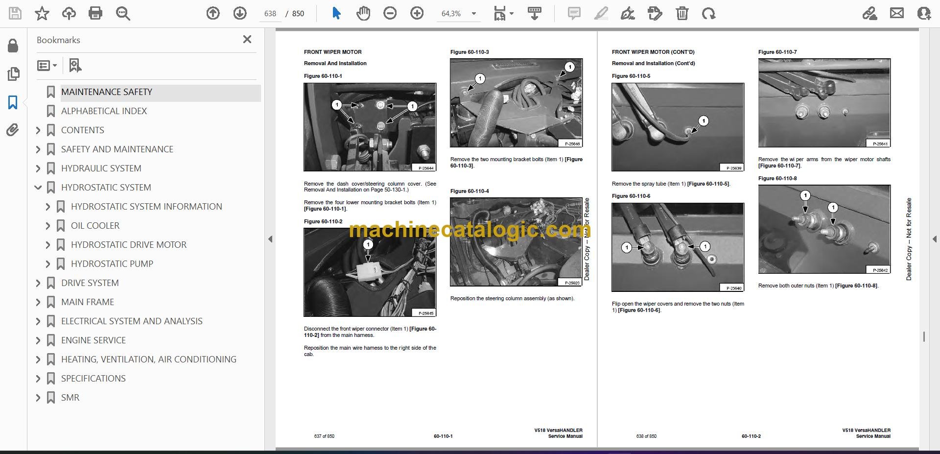
Q: Is this a searchable PDF with readable wiring diagrams?

A: Yes, it's a PDF that you can search, and wiring diagrams are set up so you can zoom in on circuits and connector details.

Q: Does it cover my machine's serial number?

A: It's written for V518 VersaHANDLER TTC units in the 367012501 to 367099999 serial range. If your plate falls in that window, this is the right book.

Q: Is this the right document for scheduled maintenance only?

A: It does include maintenance procedures, but it's really aimed at repair and diagnostics. For just basic service intervals, the maintenance or operator manual may be enough.

Bottom line, if you're repairing or diagnosing a V518 in that serial range, this is the right service manual. If you only want operating tips or parts lists, it's the wrong one.

📘 Show Index

Table of Contents:

  • MAINTENANCE SAFETY
  • ALPHABETICAL INDEX
  • CONTENTS
    • FOREWORD
    • SAFETY INSTRUCTIONS
      • Fire Prevention
    • SERIAL NUMBER LOCATIONS
      • VersaHANDLER Serial Number
      • Engine Serial Number
      • Other Serial Numbers
    • DELIVERY REPORT
    • BOBCAT VersaHANDLER IDENTIFICATION
  • SAFETY AND MAINTENANCE
    • LIFTING AND BLOCKING THE VERSAHANDLER
      • Procedure
    • OPERATOR CAB
      • Emergency Exit
      • Cab Door
      • Cab Door Window
    • TRANSPORTING THE VERSAHANDLER
      • Procedure
    • TOWING THE VERSAHANDLER
      • Procedure
    • SERVICE SCHEDULE
      • Chart
    • AIR CLEANER SERVICE
      • Replacing Filter Element
    • ENGINE COOLING SYSTEM
      • Cleaning The Cooling System
      • Checking The Coolant Level
      • Replacing The Coolant
    • FUEL SYSTEM
      • Fuel Specifications
      • Filling The Fuel Tank
      • Fuel Filter
    • ENGINE LUBRICATION SYSTEM
      • Checking Engine Oil
      • Oil Chart
      • Replacing Oil And Filter
    • HYDRAULIC/HYDROSTATIC SYSTEM
      • Checking And Adding Fluid
      • Replacing Hydraulic/Hydrostatic Filter
      • Replacing Hydraulic Fluid
    • AXLES (FRONT AND REAR)
      • Checking Oil Level (Planetary Carrier)
      • Draining Oil (Planetary Carrier)
      • Checking Oil Level (Rear Differential)
      • Draining Oil (Rear Differential)
      • Checking Oil Level (Front Differential)
      • Draining Oil (Front Differential)
    • LUBRICATION
      • Procedure
    • TIRE MAINTENANCE
      • Wheel Nuts
      • Tire Rotation
      • Tire Mounting
    • SPARK ARRESTOR MUFFLER
      • Procedure
    • BOOM STOP
      • Installing Boom Stop
      • Removing Boom Stop
    • ENGINE COVER
      • Opening And Closing The Engine Cover
      • Adjusting The Latch
    • LATERAL OPERATOR RESTRAINT SYSTEM (LORS™)
      • System Inspection
      • System Maintenance
  • HYDRAULIC SYSTEM
    • HYDRAULIC/HYDROSTATIC SCHEMATICS
    • HYDRAULIC SYSTEM INFORMATION
      • Troubleshooting Chart
      • Tightening Procedures
    • LIFT CYLINDER
      • Removal And Installation
      • Parts Identification
      • Disassembly
      • Assembly
    • BUCKET POSITIONING CYLINDER
      • Removal And Installation
      • Parts Identification
      • Disassembly
      • Assembly
    • EXTENSION CYLINDER
      • Cylinder Group Removal And Installation
      • Upper Tubeline Removal
      • Extension Cylinder Removal And Installation
      • Tubeline Tray Disassembly
      • Tubeline Tray Assembly
      • Parts Identification
      • Disassembly
      • Assembly
    • TILT CYLINDER
      • Removal And Installation
      • Parts Identification
      • Disassembly
      • Assembly
    • STEERING CYLINDER (FRONT)
      • Removal And Installation
      • Parts Identification
      • Disassembly
      • Assembly
    • STEERING CYLINDER (REAR)
      • Removal And Installation
      • Parts Identification
      • Disassembly
      • Assembly
    • DRIVE BOX
      • Parts Identification
      • Disassembly
      • Inspection
      • Assembly
    • MAIN RELIEF VALVE
      • Testing And Adjustment
      • Removal and Installation
    • QUICK TACH CYLINDER
      • Removal And Installation
      • Parts Identification
      • Disassembly
      • Assembly
    • PORT RELIEF VALVES
      • Adjustment Procedure
    • STEERING MODE VALVE BLOCK
      • Removal And Installation
      • Parts Identification
      • Disassembly
      • Solenoid Testing
      • Assembly
    • BRAKE VALVE
      • Removal And Installation
      • Disassembly And Assembly
    • GEAR PUMP
      • Removal And Installation
      • Parts Identification
      • Disassembly And Assembly
    • FAN MOTOR
      • Removal And Installation
      • Parts Identification
      • Disassembly and Assembly
    • HYDRAULIC RESERVOIR
      • Removal And Installation
    • STEERING VALVE
      • Removal And Installation
      • Parts Identification
      • Disassembly
      • Inspection
      • Assembly
    • HYDRAULIC CONTROL VALVE
      • Removal And Installation
      • Parts Identification
      • Disassembly And Assembly
      • End Housing Disassembly And Assembly
      • Lifting Valve Section Disassembly And Assembly
      • Tilting Valve Section Disassembly And Assembly
      • Telescoping Valve Section Disassembly And Assembly
      • Auxiliary Valve Section Disassembly And Assembly
      • Inlet-Outlet Valve Section Disassembly And Assembly
    • JOYSTICK
      • Handle Removal And Installation
      • Joystick Removal And Installation
      • Parts Identification
      • Disassembly And Assembly
    • PARKING BRAKE
      • Pressure Switch Removal And Installation
      • Pressure Switch Disassembly And Assembly
      • Parking Brake Valve Removal And Installation
      • Parking Brake Valve Disassembly And Assembly
    • PRESSURE REDUCING VALVE
      • Testing
      • Removal And Installation
      • Disassembly And Assembly
    • ACCUMULATOR
      • Removal And Installation
    • TOW VALVE
      • Removal And Installation
      • Disassembly And Assembly
    • FRONT AUXILIARY HYDRAULIC PRESSURE RELEASE VALVE
      • Removal And Installation
      • Disassembly And Assembly
    • FLOW CONTROL VALVE
      • Removal And Installation
  • HYDROSTATIC SYSTEM
    • HYDROSTATIC SYSTEM INFORMATION
      • Troubleshooting Chart
      • Replenishing Valve Function
    • OIL COOLER
      • Removal And Installation
    • HYDROSTATIC DRIVE MOTOR
      • Removal And Installation
      • Parts Identification
      • Disassembly
      • Inspection
      • Assembly
    • HYDROSTATIC PUMP
      • Removal And Installation
      • Parts Identification
      • Disassembly
      • Inspection
      • Assembly
  • DRIVE SYSTEM
    • TROUBLESHOOTING
      • Chart
    • AXLE AND DIFFERENTIAL (FRONT)
      • General Information
      • Planetary Carrier Parts Identification
      • Planetary Carrier Disassembly
      • Planetary Carrier Inspection
      • Wheel Hub Parts Identification
      • Wheel Hub Disassembly
      • Wheel Hub Inspection
      • Steering Knuckle Parts Identification
      • Steering Knuckle Disassembly
      • Axle Housing/Drive Axle Parts Identification
      • Axle Housing/Drive Axle Disassembly
      • Brake Group Parts Identification
      • Brake Group Disassembly
      • Brake Group Inspection
      • Differential Parts Identification
      • Differential Disassembly
      • Differential Inspection
      • Pinion Group Parts Identification
      • Pinion Group Disassembly
      • Pinion Group Inspection
      • Pinion Group Assembly
      • Differential Assembly
      • Brake Group Assembly
      • Axle Housing/Drive Axle Assembly
      • Steering Knuckle Assembly
      • Wheel Hub Assembly
      • Planetary Carrier Assembly
    • AXLE AND DIFFERENTIAL (REAR)
      • General Information
      • Planetary Carrier Parts Identification
      • Planetary Carrier Disassembly
      • Planetary Carrier Inspection
      • Wheel Hub Parts Identification
      • Wheel Hub Disassembly
      • Wheel Hub Inspection
      • Steering Knuckle Parts Identification
      • Steering Knuckle Disassembly
      • Axle Housing/Drive Axle Parts Identification
      • Axle Housing/Drive Axle Disassembly
      • Differential Parts Identification
      • Differential Disassembly
      • Differential Inspection
      • Pinion Group Parts Identification
      • Pinion Group Disassembly
      • Pinion Group Inspection
      • Pinion Group Assembly
      • Differential Assembly
      • Axle Housing/Drive Axle Assembly
      • Steering Knuckle Assembly
      • Wheel Hub Assembly
      • Planetary Carrier Assembly
    • FRONT AXLE
      • Removal
      • Installation
    • AXLE TOE-IN
      • Adjustment
    • PARKING BRAKE
      • Releasing The Brake For Towing
      • Re-Activating The Brake
    • STEERING ANGLE ADJUSTMENT
      • Adjustment
    • DRIVESHAFT
      • Removal And Installation
    • SERVICE BRAKE
      • Description
      • Bleeding The Brake Circuit
    • REAR AXLE
      • Removal
      • Installation
  • MAIN FRAME
    • OPERATOR CAB
      • Removal And Installation
    • CANOPY
      • Removal and Installation
    • OPERATOR SEAT
      • Removal And Installation
    • BOOM ASSEMBLY
      • Removal And Installation
    • INNER BOOM
      • Removal
      • Installation
    • WEAR PADS (FRONT)
      • Removal And Installation
    • WEAR PADS (REAR)
      • Removal
      • Installation
    • ENGINE COVER
      • Gas Cylinder Removal And Installation
      • Removal And Installation
    • FUEL TANK
      • Removal And Installation
    • QUICK TACH
      • Removal And Installation
    • REAR WEIGHTS
      • Removal And Installation
    • FENDER
      • Removal And Installation
    • JOYSTICK PANEL
      • Removal And Installation
    • DASH COVER/STEERING COLUMN COVER
      • Removal And Installation
  • ELECTRICAL SYSTEM AND ANALYSIS
    • ELECTRICAL SCHEMATICS
    • ELECTRICAL SYSTEM INFORMATION
      • Troubleshooting Chart
      • Description
      • Fuses, Diodes & Relays
    • BATTERY
      • Removal And Installation
      • Servicing
      • Using A Booster Battery (Jump Starting)
    • ALTERNATOR
      • Removal And Installation
      • Adjusting The Alternator Belt
    • STARTER
      • Removal And Installation
      • Parts Identification
      • Disassembly And Assembly
      • Inspection And Repair
      • Magnetic Switch Test
    • LATERAL OPERATOR RESTRAINT SYSTEM (LOR’S™)
      • Restraint Bar Removal And Installation
      • Sensor Removal And Installation
      • Strut Removal And Installation
      • Strut Disassembly And Assembly
      • Restraint Bar Bushing Removal And Installation
      • Restraint Bar Bumper Removal And Installation
    • LIGHTS
      • Rear Light Removal And Installation
      • Front Light Removal And Installation
    • TRAVEL/SIGNAL LEVER
      • Removal And Installation
    • INSTRUMENT PANEL
      • Removal And Installation
    • SWITCH PANEL
      • Removal And Installation
    • BRAKE LIGHT SWITCH
      • Removal And Installation
      • Adjustment
    • FRONT WIPER MOTOR
      • Removal And Installation
    • TOP WIPER MOTOR
      • Removal And Installation
    • REAR WIPER MOTOR
      • Removal And Installation
    • PEDAL ASSEMBLY
      • Removal And Installation
      • Disassembly And Assembly
    • INCHING SWITCH
      • Removal And Installation
      • Adjustment
    • SERVICE SOFTWARE
      • Connecting The Laptop Computer
      • Entering The Service Software
      • Monitor Screen
      • Warnings Screen
      • Calibrate Inch Pedal
      • Calibrate Creep Potentiometer
      • Program/Update Susmic Controller
  • ENGINE SERVICE
    • TROUBLESHOOTING
      • Chart
    • ENGINE SPEED CONTROL
      • Removal And Installation
    • MUFFLER
      • Removal And Installation
    • AIR CLEANER
      • Housing Removal And Installation
    • RADIATOR
      • Removal And Installation
      • Disassembly And Assembly
    • ENGINE AND ENGINE MOUNTS
      • Removal And Installation
    • ENGINE COMPONENTS AND TESTING
      • Fuel Injection Pump Removal And Installation
      • Fuel Injector Removal And Installation
      • Fuel Injector Checking
      • Checking The Fuel Lift Pump
      • Fuel Lift Pump Removal And Installation
    • ENGINE/HYDROSTAT ASSEMBLY
      • Removal And Installation
    • FLYWHEEL AND HOUSING
      • Removal And Installation
      • Ring Gear Removal
      • Ring Gear Installation
    • RECONDITIONING THE ENGINE
      • Intake Manifold Removal and Installation
      • Exhaust Manifold Removal and Installation
      • Cylinder Head Disassembly
      • Cylinder Head Removal
      • Cylinder Head Inspection
      • Cylinder Head Installation
      • Rocker Shaft Disassembly And Assembly
      • Valve Removal
      • Valve Springs Checking
      • Valve Depth Checking
      • Valve Guides Checking
      • Valve Guide Removal
      • Valve Guide Installation
      • Valves Checking
      • Cutting A Valve Seat
      • Valve Seat Assembly
      • Changing Valve Springs (With Cylinder Head Installed)
      • Valve Clearance Adjustment
      • Timing Case And Drive Assembly Description
      • Timing Cover Removal
      • Timing Cover Installation
      • Front Oil Seal Removal
      • Front Oil Seal Installation
      • Timing Case And Gear Removal
      • Timing Case And Gear Installation
      • Camshaft And Tappets Removal
      • Camshaft And Tappets Installation
      • Pistons And Connecting Rods Description
      • Pistons And Connecting Rods Removal
      • Pistons And Connecting Rods Disassembly
      • Piston Ring End Gap
      • Piston Ring Installation
      • Piston Ring Groove Clearance
      • Connecting Rod Inspection
      • Connecting Rod Bushing Replacement
      • Piston And Connecting Rod Assembly
      • Piston And Connecting Rod Installation
      • Checking Piston Height
      • Crankshaft And Bearings Description
      • Crankshaft And Bearings Removal
      • Inspection Of Crankshaft And Bearings
      • Crankshaft And Bearings Installation
      • Rear Oil Seal Removal
      • Rear Oil Seal Housing Positioning
      • Rear Oil Seal Installation
      • Checking Crankshaft End Play
      • Cooling System Description
      • Thermostat Removal and Installation
      • Thermostat Testing
      • Water Pump Removal
      • Water Pump Installation
      • Engine Lubrication System Description
      • Oil Filter Adapter Removal
      • Oil Filter Adapter Installation
      • Oil Pan Removal And Installation
      • Oil Screen And Pick-up Tube
      • Oil Pump Removal
      • Oil Pump Installation
      • Oil Pump Disassembly And Assembly
      • Oil Pressure Relief Valve Disassembly And Assembly
      • Engine Block Description
      • Engine Block Disassembly And Assembly
      • Piston Cooling Jet Removal
      • Piston Cooling Jet Installation
      • Piston Cooling Jet Alignment
      • Inspection
      • Cylinder Liner Inspection
      • Cylinder Liner Removal
      • Cylinder Liner Installation
      • Turbo Charger Troubleshooting
      • Turbo Charger Description
      • Turbo Charger Removal and Installation
  • HEATING, VENTILATION, AIR CONDITIONING
    • AIR CONDITIONING SYSTEM FLOW
      • Principals
      • Chart
    • COMPONENTS
      • Identification
    • SAFETY
      • Safety Equipment
    • REGULAR MAINTENANCE
      • Filter Element Removal And Installation
      • Compressor Drive Belt Inspection
      • Cleaning The Condenser
    • BASIC TROUBLESHOOTING
      • Poor A/C Performance
      • Compressor Drive Belt Inspection
      • Checking The Electrical System
    • GENERAL AIR CONDITIONING SERVICE GUIDELINES
      • Compressor Oil
      • Compressor Oil Check
      • Component Replacement And Refrigeration Leaks
    • SYSTEM TROUBLESHOOTING CHART
      • Chart
      • Gauge Pressure Related Troubleshooting
    • TEMPERATURE/PRESSURE
      • Chart
    • AIR CONDITIONING SERVICE
      • Chart
    • SYSTEM CHARGING AND RECLAMATION
      • Reclamation Procedure
      • Charging Procedure With A Manifold Gauge Set
      • Charging Procedure
    • COMPRESSOR
      • Removal And Installation
      • Compressor Clutch Disassembly And Assembly
    • CONDENSER
      • Removal And Installation
    • RECEIVER/DRIER
      • Removal And Installation
    • PRESSURE SWITCH
      • Removal And Installation
    • EVAPORATOR/BLOWER UNIT
      • Removal And Installation
    • EXPANSION VALVE
      • Removal And Installation
    • HEATER ASSEMBLY
      • Removal And Installation
      • Fan Removal And Installation
      • Core Removal And Installation
  • SPECIFICATIONS
    • VERSAHANDLER SPECIFICATIONS
      • Dimensional Specifications
      • Performance Specifications
      • Engine
      • Controls
      • Drive System
      • Tires
      • Hydraulic System
      • Electrical System
      • Instrument Panel
      • Capacities
    • ENGINE SPECIFICATIONS
      • General
      • Cylinder Head
      • Valve Guides
      • Exhaust Valves
      • Intake Valves
      • Valve Springs
      • Rocker Shaft, Rockers And Bushings
      • Pistons And Piston Rings
      • Connecting Rods And Bearings
      • Crankshaft
      • Crankshaft Re-Grind Data
      • Main Bearings
      • Thrust Washers
      • Camshaft And Thrust Washer
      • Cylinder Block
      • Cylinder Liners
      • Fuel Injection Pump
      • Fuel Injectors
      • Fuel Lift Pump
      • Timing Case And Timing Gears
      • Oil Pump, Gear And Relief Valve
      • Turbocharger
      • Flywheel
      • Water Pump And Thermostat
      • Engine Torque Component
    • MACHINE TORQUE SPECIFICATIONS
      • Specifications
    • TORQUE SPECIFICATIONS FOR BOLTS
      • Torque for General SAE Bolts
      • Torque For General Metric Bolts
    • HYDRAULIC CONNECTION SPECIFICATIONS
      • O-ring Face Seal Connection
      • Straight Thread O-ring Fitting
      • Tubelines And Hoses
      • Flare Fitting
      • O-ring Flare Fitting
      • Port Seal Fitting
    • HYDRAULIC/HYDROSTATIC FLUID SPECIFICATIONS
      • Specifications
    • CONVERSIONS
      • Decimal And Millimeter Equivalents
      • U.S. To Metric Conversion
  • SMR
    • V518-1
    • V518-2

Bobcat Software

Bobcat PDF Manuals

Related Manuals

0
    0
    Your Cart
    Your cart is emptyReturn to Shop