$ 0
0
$ 0
0

Bobcat V623 VersaHANDLER® TTC, Telescopic Handler Service Manual (SN 367211001-367213000)

Format: PDF (Printable Document)

File Language: English

File Pages: 786

File Size: 27.10 MB (Speed Download Link)
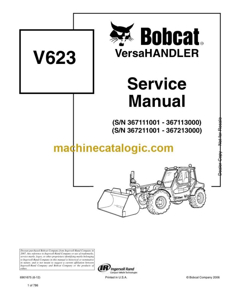
Brand: Bobcat

Model: V623 VersaHANDLER® TTC, Telescopic Handler

Book No: 6901675

Serial No: SN 367211001-367213000

Type of Document: Service Manual

Categories: ,

$ 45

Share:

Bobcat V623 VersaHANDLER® TTC, Telescopic Handler Service Manual (SN 367211001-367213000)

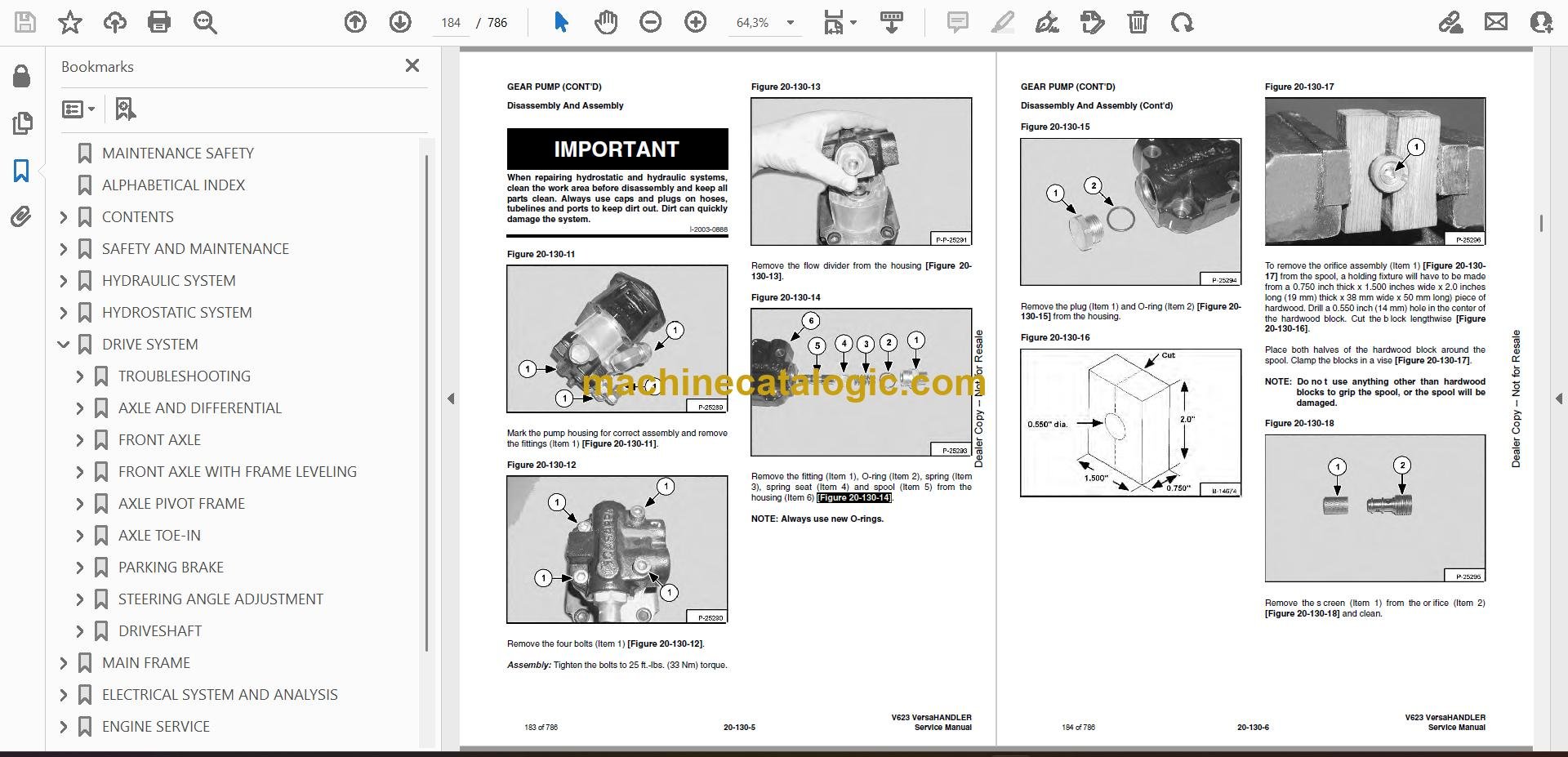
A V623 VersaHANDLER is the telehandler you see loading seed totes, placing roofing pallets, or lifting trusses where a skid-steer just won't reach. The service manual is what I grab when my truck stock and experience aren't enough and I need the exact procedure for that specific serial range. Buyers use it when they're chasing hydraulic issues, driveline problems, or electrical gremlins and don't want to guess. If you're working on a V623 in the 367211001-367213000 range, this is the book you'd expect to have on the bench or pulled up on a laptop in the mud.

What this manual helps you do

  • Diagnose hydraulic issues in the boom and stabilizers, and pressure-test circuits on the V623.
  • Trace and repair electrical faults using proper wiring diagrams for this telehandler.
  • Check and set adjustments on the telescopic boom, steering, and drive system components.
  • Follow step-by-step teardown and reassembly for major components like axles, cylinders, and pumps.
  • Verify specs after repairs so you know the machine is back within Bobcat's limits for this serial range.

Who this is for

This is for small contractors, rental fleets, shop mechanics, and owner-operators running a Bobcat V623 VersaHANDLER in the 367211001-367213000 serial block. If you just need basic operating tips or daily checks, you want the operator's handbook instead, not this service manual.

FAQ

Q: Is this a searchable PDF, and can I read the wiring diagrams clearly on a laptop or tablet?

A: These manuals are usually supplied as searchable PDFs, and the wiring diagrams are made to be zoomed so you can read pin numbers and wire colors.

Q: My V623 serial number is outside 367211001-367213000. Will this still match my machine?

A: No, this manual is targeted to that exact serial range. If yours is outside it, you should look for the correct range to avoid wrong procedures or specs.

Q: I'm just changing fluids and filters. Do I really need this manual?

A: For simple maintenance, you can get by with the operator's handbook, but for real diagnostics or component work, this is the right document.

Bottom line, if you own or service a Bobcat V623 VersaHANDLER in serial range 367211001-367213000 and plan to do real repair work, this is the correct service manual.

📘 Show Index

Table of Contents:

  • MAINTENANCE SAFETY
  • ALPHABETICAL INDEX
  • CONTENTS
    • FOREWORD
    • SAFETY INSTRUCTIONS
      • Fire Prevention
    • SERIAL NUMBER LOCATIONS
      • VersaHANDLER Serial Number
      • Engine Serial Number
      • Other Serial Numbers
    • DELIVERY REPORT
    • BOBCAT VersaHANDLER IDENTIFICATION
  • SAFETY AND MAINTENANCE
    • LIFTING AND BLOCKING THE VERSAHANDLER
      • Procedure
    • OPERATOR CAB
      • Emergency Exit
      • Cab Door
      • Cab Door Window
    • TRANSPORTING THE VERSAHANDLER
      • Procedure
    • TOWING THE VERSAHANDLER
      • Procedure
    • SERVICE SCHEDULE
      • Chart
    • AIR CLEANER SERVICE
      • Replacing Filter Element
    • ENGINE COOLING SYSTEM
      • Cleaning The Cooling System
      • Checking The Coolant Level
      • Replacing The Coolant
    • FUEL SYSTEM
      • Fuel Specifications
      • Filling The Fuel Tank
      • Fuel Filter
    • ENGINE LUBRICATION SYSTEM
      • Checking Engine Oil
      • Oil Chart
      • Replacing Oil And Filter
    • HYDRAULIC/HYDROSTATIC SYSTEM
      • Checking And Adding Fluid
      • Replacing Hydraulic/Hydrostatic Filter
      • Replacing Hydraulic Fluid
    • AXLES (FRONT AND REAR)
      • Checking Oil Level (Planetary Carrier)
      • Draining Oil (Planetary Carrier)
      • Checking Oil Level (Rear Differential)
      • Draining Oil (Rear Differential)
      • Checking Oil Level (Front Differential)
      • Draining Oil (Front Differential)
    • LUBRICATION
      • Procedure
    • TIRE MAINTENANCE
      • Wheel Nuts
      • Tire Rotation
      • Tire Mounting
    • SPARK ARRESTOR MUFFLER
    • BOOM STOP
      • Installing Boom Stop
      • Removing Boom Stop
    • ENGINE COVER
      • Opening And Closing The Engine Cover
      • Adjusting The Latch
  • HYDRAULIC SYSTEM
    • HYDRAULIC/HYDROSTATIC SCHEMATICS
    • HYDRAULIC SYSTEM INFORMATION
      • Troubleshooting Chart
      • Tightening Procedures
    • LIFT CYLINDER
      • Removal And Installation
      • Parts Identification
      • Disassembly
      • Assembly
    • BUCKET POSITIONING CYLINDER
      • Removal And Installation
      • Parts Identification
      • Disassembly
      • Assembly
    • EXTENSION CYLINDER
      • Removal And Installation
      • Parts Identification
      • Disassembly
      • Assembly
    • TILT CYLINDER
      • Removal And Installation
      • Parts Identification
      • Disassembly
      • Assembly
    • STEERING CYLINDER
      • Removal And Installation
      • Parts Identification
      • Disassembly
      • Assembly
    • DRIVE BOX
      • Parts Identification
      • Disassembly
      • Inspection
      • Assembly
    • MAIN RELIEF VALVE
      • Testing And Adjustment
      • Removal and Installation
    • QUICK TACH CYLINDER
      • Removal And Installation
      • Parts Identification
      • Disassembly
      • Assembly
    • FRAME LEVELING CYLINDER
      • Removal And Installation
      • Parts Identification
      • Disassembly
      • Assembly
    • STEERING MODE VALVE BLOCK
      • Removal And Installation
      • Parts Identification
      • Disassembly
      • Solenoid Testing
      • Assembly
    • BRAKE VALVE
      • Removal And Installation
    • GEAR PUMP
      • Removal And Installation
      • Parts Identification
      • Disassembly And Assembly
    • FAN MOTOR
      • Removal And Installation
      • Parts Identification
      • Disassembly and Assembly
    • HYDRAULIC RESERVOIR
      • Removal And Installation
    • STEERING VALVE
      • Removal And Installation
      • Parts Identification
      • Disassembly
      • Inspection
      • Assembly
    • HYDRAULIC CONTROL VALVE (S/N 367111001- 367112500 AND 367211001-367212500)
      • Removal And Installation
      • Parts Identification
      • Disassembly And Assembly
      • Frame Leveling Valve Section (Optional)
      • Auxiliary Valve Section
      • Telescoping Valve Section
      • Tilting Valve Section
      • Lifting Valve Section
      • Inlet/Outlet Valve Section
    • HYDRAULIC CONTROL VALVE (S/N 367112501- 367113000 AND 367212501-367213000)
      • Removal And Installation
      • Parts Identification
      • Disassembly And Assembly
      • End Housing Disassembly And Assembly
      • Lifting Valve Section Disassembly And Assembly
      • Tilting Valve Section Disassembly And Assembly
      • Telescoping Valve Section Disassembly And Assembly
      • Auxiliary Valve Section Disassembly And Assembly
      • Frame Leveling Valve Section Disassembly And Assembly (If Equipped)
      • Inlet-Outlet Valve Section Disassembly And Assembly
    • JOYSTICK (S/N 367112501-367113000 AND 367212501-367213000)
      • Handle Removal And Installation
      • Joystick Removal And Installation
      • Parts Identification
      • Disassembly And Assembly
  • HYDROSTATIC SYSTEM
    • HYDROSTATIC SYSTEM INFORMATION
      • Troubleshooting Chart
      • Replenishing The Valve Function
    • OIL COOLER
      • Removal And Installation
    • HYDROSTATIC DRIVE MOTOR
      • Removal And Installation
      • Parts Identification
      • Disassembly
      • Inspection
      • Assembly
    • HYDROSTATIC PUMP
      • Removal And Installation
      • Parts Identification
      • Disassembly
      • Inspection
      • Assembly
  • DRIVE SYSTEM
    • TROUBLESHOOTING
      • Chart
    • AXLE AND DIFFERENTIAL
      • General Information
      • Planetary Carrier Parts Identification
      • Planetary Carrier Disassembly
      • Planetary Carrier Inspection
      • Wheel Hub Parts Identification
      • Wheel Hub Disassembly
      • Wheel Hub Inspection
      • Steering Knuckle Parts Identification
      • Steering Knuckle Disassembly
      • Axle Housing/Drive Axle Parts Identification
      • Axle Housing/Drive Axle Disassembly
      • Brake Group Parts Identification
      • Brake Group Disassembly
      • Brake Housing Inspection
      • Differential Parts Identification
      • Differential Disassembly
      • Differential Inspection
      • Pinion Group Parts Identification
      • Pinion Group Disassembly
      • Pinion Group Inspection
      • Pinion Group Assembly
      • Differential Assembly
      • Brake Group Assembly
      • Axle Housing/Drive Axle Assembly
      • Steering Knuckle Assembly
      • Wheel Hub Assembly
      • Planetary Carrier Assembly
    • FRONT AXLE
      • Removal
      • Installation
    • FRONT AXLE WITH FRAME LEVELING
      • Removal
      • Installation
    • AXLE PIVOT FRAME
      • Removal And Installation
      • Bushing Removal And Installation
    • AXLE TOE-IN
      • Adjustment
    • PARKING BRAKE
      • Releasing The Brake For Towing
      • Re-Activating The Brake
    • STEERING ANGLE ADJUSTMENT
      • Adjustment
    • DRIVESHAFT
      • Removal And Installation
  • MAIN FRAME
    • OPERATOR CAB
      • Removal And Installation
    • OPERATOR SEAT
      • Removal And Installation
    • BOOM ASSEMBLY
      • Removal And Installation
    • INNER BOOM
      • Removal
      • Installation
    • WEAR PADS (FRONT)
      • Removal And Installation
    • WEAR PADS (REAR)
      • Removal
      • Installation
    • ENGINE COVER
      • Gas Cylinder Removal And Installation
      • Removal And Installation
    • FUEL TANK
      • Removal And Installation
    • QUICK TACH
      • Removal And Installation
    • REAR WEIGHTS
      • Removal And Installation
    • FENDER
      • Removal And Installation
    • PIVOT LINK
      • Removal And Installation
  • ELECTRICAL SYSTEM AND ANALYSIS
    • ELECTRICAL SCHEMATICS
    • ELECTRICAL SYSTEM INFORMATION
      • Troubleshooting Chart
      • Description
      • Fuses, Diodes & Relays
    • BATTERY
      • Removal And Installation
      • Servicing
      • Using A Booster Battery (Jump Starting)
    • ALTERNATOR
      • Removal And Installation
    • STARTER
      • Removal And Installation
      • Parts Identification
      • Disassembly
      • Inspection And Repair
      • Assembly
    • JOYSTICK PANEL
      • Removal And Installation
    • LIGHTS
      • Rear Removal And Installation
      • Front Removal And Installation
    • TRAVEL/SIGNAL LEVER
      • Removal And Installation
    • INSTRUMENT PANEL
      • Removal And Installation
    • SWITCH PANEL
      • Removal And Installation
    • DASH COVER/STEERING COLUMN COVER
      • Removal And Installation
    • FRONT WIPER MOTOR
      • Removal And Installation
    • TOP WIPER MOTOR
      • Removal And Installation
    • REAR WIPER MOTOR
      • Removal And Installation
    • PEDAL ASSEMBLY
      • Removal And Installation
    • BRAKE LIGHT SWITCH
      • Removal And Installation
      • Adjustment
    • INCHING SWITCH
      • Removal And Installation
      • Adjustment
    • JOYSTICK (S/N 367111001-367112500 AND 367211001-367212500)
      • Removal And Installation
  • ENGINE SERVICE
    • TROUBLESHOOTING
      • Chart
    • ENGINE SPEED CONTROL
      • Removal And Installation
      • Adjustment
    • MUFFLER
      • Removal And Installation
    • AIR CLEANER
      • Housing Removal And Installation
    • RADIATOR
      • Removal And Installation
      • Disassembly And Assembly
    • ENGINE AND ENGINE MOUNTS
      • Removal And Installation
    • ENGINE COMPONENTS AND TESTING
      • Fuel Injection Pump Removal And Installation
      • Fuel Injector Removal And Installation
      • Fuel Injector Checking
      • Checking The Fuel Lift Pump
      • Fuel Lift Pump Removal And Installation
    • ENGINE/HYDROSTAT ASSEMBLY
      • Removal And Installation
    • FLYWHEEL AND HOUSING
      • Removal And Installation
      • Ring Gear Removal
      • Ring Gear Installation
    • RECONDITIONING THE ENGINE
      • Intake Manifold Removal and Installation
      • Exhaust Manifold Removal and Installation
      • Cylinder Head Disassembly
      • Cylinder Head Removal
      • Cylinder Head Inspection
      • Cylinder Head Installation
      • Rocker Shaft Disassembly And Assembly
      • Valve Removal
      • Valve Springs Checking
      • Valve Depth Checking
      • Valve Guides Checking
      • Valve Guide Removal
      • Valve Guide Installation
      • Valves Checking
      • Cutting A Valve Seat
      • Valve Seat Assembly
      • Changing Valve Springs (With Cylinder Head Installed)
      • Valve Clearance Adjustment
      • Timing Case And Drive Assembly Description
      • Timing Cover Removal
      • Timing Cover Installation
      • Front Oil Seal Removal
      • Front Oil Seal Installation
      • Timing Case And Gear Removal
      • Timing Case And Gear Installation
      • Camshaft And Tappets Removal
      • Camshaft And Tappets Installation
      • Pistons And Connecting Rods Description
      • Pistons And Connecting Rods Removal
      • Pistons And Connecting Rods Disassembly
      • Piston Ring End Gap
      • Piston Ring Installation
      • Piston Ring Groove Clearance
      • Connecting Rod Inspection
      • Connecting Rod Bushing Replacement
      • Piston And Connecting Rod Assembly
      • Piston And Connecting Rod Installation
      • Checking Piston Height
      • Crankshaft And Bearings Description
      • Crankshaft And Bearings Removal
      • Inspection Of Crankshaft And Bearings
      • Crankshaft And Bearings Installation
      • Rear Oil Seal Removal
      • Rear Oil Seal Housing Positioning
      • Rear Oil Seal Installation
      • Checking Crankshaft End Play
      • Cooling System Description
      • Thermostat Removal and Installation
      • Thermostat Testing
      • Water Pump Removal
      • Water Pump Installation
      • Engine Lubrication System Description
      • Oil Filter Adapter Removal
      • Oil Filter Adapter Installation
      • Oil Pan Removal And Installation
      • Oil Screen And Pick-up Tube
      • Oil Pump Removal
      • Oil Pump Installation
      • Oil Pump Disassembly And Assembly
      • Oil Pressure Relief Valve Disassembly And Assembly
      • Engine Block Description
      • Engine Block Disassembly And Assembly
      • Piston Cooling Jet Removal
      • Piston Cooling Jet Installation
      • Piston Cooling Jet Alignment
      • Inspection
      • Cylinder Liner Inspection
      • Cylinder Liner Removal
      • Cylinder Liner Installation
      • Turbo Charger Troubleshooting
      • Turbo Charger Description
      • Turbo Charger Removal and Installation
  • HEATING, VENTILATION, AIR CONDITIONING
    • AIR CONDITIONING SYSTEM FLOW
      • Principals
      • Chart
    • COMPONENTS
      • Identification
    • SAFETY
      • Safety Equipment
    • REGULAR MAINTENANCE
      • Filter Element Removal And Installation
      • Compressor Drive Belt Inspection
      • Cleaning The Condenser
    • BASIC TROUBLESHOOTING
      • Poor A/C Performance
      • Compressor Drive Belt Inspection
      • Checking The Electrical System
    • GENERAL AIR CONDITIONING SERVICE GUIDELINES
      • Compressor Oil
      • Compressor Oil Check
      • Component Replacement And Refrigeration Leaks
    • SYSTEM TROUBLESHOOTING CHART
    • TEMPERATURE/PRESSURE
      • Chart
    • AIR CONDITIONING SERVICE
      • Chart
    • SYSTEM CHARGING AND RECLAMATION
      • Reclamation Procedure
      • Charging Procedure With A Manifold Gauge Set
      • Charging Procedure
    • COMPRESSOR
      • Removal And Installation
      • Compressor Clutch Disassembly
    • CONDENSER
      • Removal And Installation
    • RECEIVER/DRIER
      • Removal And Installation
    • PRESSURE SWITCH
      • Removal And Installation
    • EVAPORATOR/BLOWER UNIT
      • Removal And Installation
    • EXPANSION VALVE
      • Removal And Installation
    • HEATER ASSEMBLY
      • Removal And Installation
      • Fan Removal And Installation
      • Core Removal And Installation
  • SPECIFICATIONS
    • VERSAHANDLER SPECIFICATIONS
      • Dimensional Specifications
      • Performance Specifications
      • Engine
      • Controls
      • Drive System
      • Tires
      • Hydraulic System
      • Electrical System
      • Capacities
    • ENGINE SPECIFICATIONS
      • General
      • Cylinder Head
      • Valve Guides
      • Exhaust Valves
      • Intake Valves
      • Valve Springs
      • Rocker Shaft, Rockers And Bushings
      • Pistons And Piston Rings
      • Connecting Rods And Bearings
      • Crankshaft
      • Crankshaft Re-Grind Data
      • Main Bearings
      • Thrust Washers
      • Camshaft And Thrust Washer
      • Cylinder Block
      • Cylinder Liners
      • Fuel Injection Pump
      • Fuel Injectors
      • Fuel Lift Pump
      • Timing Case And Timing Gears
      • Oil Pump, Gear And Relief Valve
      • Turbocharger
      • Flywheel
      • Water Pump And Thermostat
      • Engine Torque
    • LOADER TORQUE SPECIFICATIONS
      • Axle
      • Boom
      • Drive Box
      • Drive Motor
      • Engine
      • Hydraulic Pump
    • TORQUE SPECIFICATIONS FOR BOLTS
      • Torque for General SAE Bolts
      • Torque For General Metric Bolts
    • HYDRAULIC CONNECTION SPECIFICATIONS
      • O-ring Face Seal Connection
      • Straight Thread O-ring Fitting
      • Tubelines And Hoses
      • Flare Fitting
      • O-ring Flare Fitting
      • Port Seal Fitting
    • HYDRAULIC/HYDROSTATIC FLUID SPECIFICATIONS
      • Specifications
    • CONVERSIONS
      • Decimal And Millimeter Equivalents
      • U.S. To Metric Conversion
  • SMR
    • V623-1
    • V623-2
    • V623-3
    • V623-4
    • V623-5

Bobcat Software

Bobcat PDF Manuals

Related Manuals

0
    0
    Your Cart
    Your cart is emptyReturn to Shop