$ 0
0
$ 0
0

Bobcat V723 VersaHANDLER® TTC, Telescopic Handler Service Manual (SN B4C311001-B4C399999)

Format: PDF (Printable Document)

File Language: English

File Pages: 843

File Size: 31.42 MB (Speed Download Link)

Brand: Bobcat

Model: V723 VersaHANDLER® TTC, Telescopic Handler

Book No: 7324187

Serial No: SN B4C311001-B4C399999

Type of Document: Service Manual

Categories: ,

$ 45

Share:

Bobcat V723 VersaHANDLER® TTC, Telescopic Handler Service Manual (SN B4C311001-B4C399999)

A V723 VersaHANDLER is the farm and yard "telehandler" that loads seed, stacks bales, and feeds trucks where a skid steer just can't reach. When one goes down, you're dead in the water for stacking, loading, or running pallet forks. The service manual is what the shop guy, field tech, or owner-operator pulls when a warning light is on, a boom function dies, or a drive issue shows up and you've only got a weekend to sort it out.

What this manual helps you do

  • Diagnose hydraulic issues in the boom, outriggers, and steering using step-by-step checks and pressure test procedures.
  • Trace and repair electrical faults with wiring diagrams and connector locations for this V723 TTC series.
  • Follow teardown and reassembly steps for cylinders, drive components, and major hydraulic blocks on the V723.
  • Check and set adjustments on linkages, boom sections, brakes, and steering so the handler runs straight and lifts right.
  • Replace and verify engine, drivetrain, and hydraulic components using the correct sequences and specs for this exact serial range.

Who this is for

This is for a V723 VersaHANDLER TTC owner, small contractor, rental fleet, or shop mechanic working on machines in the B4C311001 to B4C399999 serial range. If you just want to learn controls, daily checks, or safety info, you need the operator's handbook instead, not this service manual.

FAQ

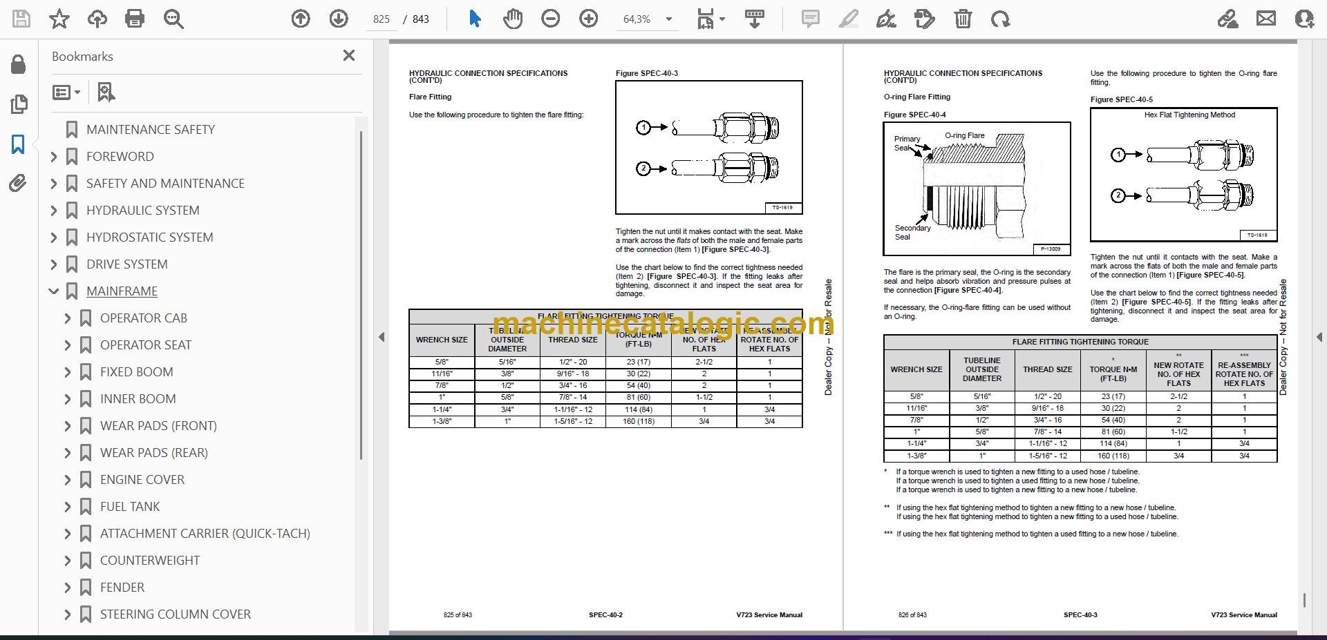
Q: Is this a searchable PDF, and can I read the wiring diagrams clearly?

A: Yes, these manuals are usually supplied as searchable PDFs, and the wiring diagrams are laid out so you can zoom in and read pin numbers and color codes.

Q: How do I know if it fits my machine?

A: Check your V723 serial number plate. If it falls between B4C311001 and B4C399999, this is the right service manual.

Q: Is this the right book if I'm doing my own repairs?

A: Yes, this is the workshop-level manual, meant for real repairs and diagnostics, not just basic operation.

If your V723 serial number is in that B4C311001-B4C399999 window and you're planning to wrench on it yourself, this is the manual you want. If the serial is outside that range, it isn't the right one.

📘 Show Index

Table of Contents:

  • MAINTENANCE SAFETY
  • FOREWORD
    • FOREWORD
    • SAFETY INSTRUCTIONS
    • FIRE PREVENTION
      • Maintenance
      • Operation
      • Electrical
      • Hydraulic System
      • Fueling
      • Starting
      • Spark Arrester Exhaust System
      • Welding And Grinding
      • Fire Extinguishers
    • SERIAL NUMBER LOCATION
      • VersaHANDLER Serial Number
      • Engine Serial Number
    • DELIVERY REPORT
    • BOBCAT VERSAHANDLER IDENTIFICATION
  • SAFETY AND MAINTENANCE
    • LIFTING AND BLOCKING THE VERSAHANDLER
      • Procedure
    • OPERATOR CAB
      • Description
      • Cab Door
      • Cab Door Window
      • Rear Cab Window
      • Cab Light
    • TRANSPORTING THE VERSAHANDLER ON A TRAILER
      • Loading And Unloading
      • Fastening
    • TOWING THE VERSAHANDLER
      • Procedure
    • SERVICE SCHEDULE
      • Maintenance Intervals
    • ENGINE AIR CLEANER
      • Replacing Filter Elements
      • Daily Check
      • Replacing Filter Elements
    • ENGINE COOLING SYSTEM
      • Cleaning
      • Checking Level
      • Removing And Replacing The Coolant
    • FUEL SYSTEM
      • Fuel Specifications
      • Biodiesel Blend Fuel
      • Filling The Fuel Tank
      • Fuel Filter
      • Removing Air From The Fuel System
    • ENGINE LUBRICATION SYSTEM
      • Checking And Adding Engine Oil
      • Engine Oil Chart
      • Removing And Replacing Oil And Filter
    • HYDRAULIC / HYDROSTATIC SYSTEM
      • Checking And Adding Fluid
      • Hydraulic / Hydrostatic Fluid Chart
      • Removing And Replacing Hydraulic Fluid
      • Removing And Replacing Hydraulic / Hydrostatic Filter
      • Removing And Replacing Hydraulic Charge Filter
      • Fill / Breather Cap
    • AXLES (FRONT AND REAR)
      • Checking And Adding Oil (Planetary Carrier)
      • Removing And Replacing Oil (Planetary Carrier)
      • Checking And Adding Oil (Rear Differential)
      • Removing And Replacing Oil (Rear Differential)
      • Checking And Adding Oil (Front Differential)
      • Removing And Replacing Oil (Front Differential)
      • Checking And Adding Oil (Reduction Box)
      • Removing And Replacing Oil (Reduction Box)
    • LUBRICATING THE VERSAHANDLER
      • Lubrication Locations
    • ATTACHMENT CARRIER
      • Inspection And Maintenance
    • TIRE MAINTENANCE
      • Wheel Nuts
      • Rotating
      • Wheel Replacement
      • Mounting
      • Pressure
    • APPROVED BOOM STOP
      • Installing The Approved Boom Stop
      • Removing The Approved Boom Stop
    • ENGINE COVER
      • Opening And Closing
    • STOPPING THE ENGINE AND LEAVING THE VERSAHANDLER
      • Procedure
    • EMERGENCY EXIT
      • Rear Window
    • VERSAHANDLER STORAGE AND RETURN TO SERVICE
      • Storage
      • Return To Service
    • LIFTING THE VERSAHANDLER
      • Procedure
    • REMOTE START TOOL (SERVICE TOOL) KIT – MEL1563
      • Remote Start Tool – MEL1563
      • Service Tool Harness Control – MEL1565
      • Service Tool Harness Communicator – MEL1566
    • REMOTE START TOOL (SERVICE TOOL) KIT – 7217666
      • Remote Start Tool (Service Tool) – 7022042
      • VersaHANDLER Service Tool Harness – 6689747
      • Computer Service Tool Harness – 6689746
      • Remote Start Procedure
  • HYDRAULIC SYSTEM
    • HYDRAULIC / HYDROSTATIC SCHEMATICS
    • HYDRAULIC SYSTEM INFORMATION
      • Glossary Of Hydraulic / Hydrostatic Symbols
      • Troubleshooting Chart
      • Tightening Procedures
    • LIFT CYLINDER
      • Removal And Installation
      • Parts Identification
      • Disassembly
      • Assembly
    • SELF LEVELING CYLINDER
      • Removal And Installation
      • Parts Identification
      • Disassembly
      • Assembly
    • SELF LEVELING CYLINDER (LOCK VALVE)
      • Removal And Installation
    • EXTENSION CYLINDER
      • Cylinder Group Removal And Installation
      • Upper Tubeline Removal And Installation
      • Extension Cylinder Removal And Installation
      • Tubeline Tray Disassembly
      • Parts Identification
      • Disassembly
      • Assembly
    • TILT CYLINDER
      • Removal And Installation
      • Parts Identification
      • Disassembly
      • Assembly
    • STEERING CYLINDER (FRONT / REAR)
      • Removal
      • Installation
      • Disassembly
      • Assembly
    • GEAR CONTROL CYLINDER
      • Removal
      • Parts Identification
      • Disassembly
      • Assembly
      • Installation
    • COLLECTOR BLOCK
      • Removal And Installation
      • Parts Identification
      • Disassembly And Assembly
    • BRAKE VALVE
      • Removal And Installation
    • GEAR PUMP
      • Steering And Valve Gear Pump Direct Test
      • Removal And Installation
      • Parts Identification
      • Disassembly And Assembly
    • FAN MOTOR
      • Removal And Installation
      • Parts Identification (Single Speed Version) (Standard)
      • Disassembly And Assembly (Single Speed Version) (Standard)
      • Parts Identification (Variable Speed Version) (Optional)
      • Disassembly And Assembly (Variable Speed Version) (Optional)
    • HYDRAULIC FLUID RESERVOIR
      • Removal And Installation
    • STEERING VALVE
      • Removal And Installation
    • HYDRAULIC CONTROL VALVE
      • Troubleshooting Chart (Solenoid Valves)
      • Valve Section Troubleshooting
      • Troubleshooting Chart (Control Valve)
      • Main Relief Valve Testing And Adjustment
      • Main Relief Valve Removal And Installation
      • Removal And Installation
      • Parts Identification
      • Disassembly And Assembly
      • Inlet-Outlet Valve Section Disassembly And Assembly
      • Lifting Valve Section Disassembly And Assembly
      • Tilting Valve Section Disassembly And Assembly
      • Telescoping Valve Section Disassembly And Assembly
      • Auxiliary Valve Section Disassembly And Assembly
      • End Housing Disassembly And Assembly
    • PORT RELIEF VALVES
      • Testing
      • Replacement Procedure
    • BOOM SUSPENSION VALVE ACCUMULATOR
      • Removal And Installation
    • AUXILIARY HYDRAULIC FLOW
      • Testing The Auxiliary Hydraulic Flow
  • HYDROSTATIC SYSTEM
    • HYDROSTATIC SYSTEM INFORMATION
      • Troubleshooting Chart
      • Replenishing Valve Function
    • OIL COOLER
      • Description
    • HYDROSTATIC DRIVE MOTOR
      • Removal And Installation
      • Parts Identification
      • Disassembly
      • Inspection
      • Assembly
    • HYDROSTATIC PUMP
      • Calibration
      • Swash Plate Calibration – Neutral Range
      • Swash Plate Calibration – Maximum Range
      • Removal And Installation
      • Parts Identification
      • Shaft Disassembly
      • Relief Valves Disassembly And Assembly
      • Charge Pump Disassembly
      • Piston Pump Disassembly
      • Solenoid Block Disassembly
      • Inspection
      • Piston Pump Assembly
      • Charge Pump Assembly
      • Solenoid Block Assembly
      • Shaft Assembly
    • CHARGE PRESSURE
      • Description
      • Testing And Adjusting
    • MULTI-FUNCTION VALVES
      • Description
      • Testing
  • DRIVE SYSTEM
    • DRIVE SYSTEM TROUBLESHOOTING
      • Chart
    • AXLE AND DIFFERENTIAL (FRONT)
      • Description
      • Planetary Carrier Parts Identification
      • Planetary Carrier Disassembly
      • Steering Knuckle And Drive Axle Parts Identification
      • Steering Knuckle Disassembly
      • Drive Axle Disassembly
      • Brake Group Parts Identification
      • Brake Group Disassembly
      • Differential Parts Identification
      • Differential Disassembly
      • Pinion Group Parts Identification
      • Pinion Group Disassembly
      • Pinion Group Assembly
      • Differential Assembly
      • Brake Group Assembly
      • Drive Axle Assembly
      • Steering Knuckle Assembly
      • Planetary Carrier Assembly
    • AXLE AND DIFFERENTIAL (REAR)
      • Description
      • Planetary Carrier Parts Identification
      • Planetary Carrier Disassembly
      • Steering Knuckle And Drive Axle Parts Identification
      • Steering Knuckle Disassembly
      • Differential Parts Identification
      • Differential Disassembly
      • Pinion Group Parts Identification
      • Pinion Group Disassembly
      • Pinion Group Assembly
      • Differential Assembly
      • Steering Knuckle Assembly
      • Planetary Carrier Assembly
    • FRONT AXLE
      • Removal And Installation
    • AXLE TOE-IN
      • Adjustment
    • PARKING BRAKE
      • Releasing The Brake For Towing
      • Adjustment
      • Brake Cylinder Removal
      • Brake Cylinder Disassembly And Assembly
      • Brake Disc Removal And Installation
      • Brake Cylinder Installation
    • STEERING ANGLE ADJUSTMENT
      • Adjustment
    • DRIVE SHAFT
      • Rear Drive Shaft Removal And Installation
      • Front Drive Shaft Removal And Installation
    • SERVICE BRAKE
      • Description
      • Bleeding The Brake Circuit
    • REAR AXLE
      • Removal And Installation
    • GEAR BOX
      • Removal And Installation
      • Parts Identification
      • Disassembly
      • Assembly
  • MAINFRAME
    • OPERATOR CAB
      • Removal And Installation
    • OPERATOR SEAT
      • Removal And Installation
    • FIXED BOOM
      • Removal
      • Installation
    • INNER BOOM
      • Removal And Installation
    • WEAR PADS (FRONT)
      • Removal And Installation
    • WEAR PADS (REAR)
      • Removal And Installation
    • ENGINE COVER
      • Gas Cylinder Removal And Installation
      • Removal And Installation
    • FUEL TANK
      • Removal And Installation
    • ATTACHMENT CARRIER (QUICK-TACH)
      • Removal And Installation
    • COUNTERWEIGHT
      • Removal And Installation
    • FENDER
      • Removal And Installation
    • STEERING COLUMN COVER
      • Removal And Installation
    • DASH COVER
      • Removal And Installation
    • JOYSTICK PANEL
      • Removal And Installation
  • ELECTRICAL SYSTEM
    • ELECTRICAL SCHEMATICS
    • ELECTRICAL SYSTEM INFORMATION
      • Glossary Of Electrical Symbols
      • Cab Harness Connectors
      • Engine Harness Connectors
      • DEF Harness Connectors
      • Mainframe Harness Connectors
      • Troubleshooting Chart
      • Description
      • Fuses And Relay Location / Identification
    • BATTERY
      • Battery Maintenance
      • Using A Booster Battery (Jump Starting)
      • Removing And Installing The Battery
    • ALTERNATOR
      • Belt Adjustment
      • Belt Checking
      • Belt Replacement
      • Removal And Installation
    • STARTER
      • Testing
      • Removal And Installation
    • LIGHTS
      • Rear Light Removal And Installation
      • Rear Light Bulb Replacement
      • Front Light Removal And Installation
      • Front Light Bulb Replacement
    • SIGNAL LEVER
      • Removal And Installation
    • DISPLAY
      • Removal And Installation
    • INSTRUMENT PANELS
      • Right Instrument And Indicator Panel Removal And Installation
      • Left Instrument Panel Removal And Installation
    • BOOM ANGLE SENSOR
      • Removal And Installation
      • Calibration
    • FRONT WIPER MOTOR
      • Removal And Installation
    • TOP WIPER MOTOR
      • Removal And Installation
    • REAR WIPER MOTOR
      • Removal And Installation
    • PEDAL ASSEMBLY
      • Removal And Installation
    • INCHING SENSOR
      • Removal And Installation
      • Calibration
    • SERVICE PC (LAPTOP COMPUTER)
      • Connecting Remote Start Tool (Service Tool) – MEL1563
      • Connecting Remote Start Tool (Service Tool) – 7217666
    • FUEL LEVEL SENDER
      • Removal And Installation
    • JOYSTICK
      • Removal And Installation
    • MAINTENANCE CLOCK
      • Description
      • Setup
      • Reset
    • RETRACT SENSOR
      • Removal And Installation
      • Adjustment
  • ENGINE SERVICE
    • ENGINE INFORMATION
      • Description
      • Specifications
      • Sensor Location
      • Torque Values
      • Troubleshooting
      • Removal And Installation
      • Compression – Testing
      • Oil Pressure Testing (At Oil Sensor On Block)
      • Oil Pressure Testing (At Turbocharger Oil Inlet)
    • ENGINE AND HYDROSTAT ASSEMBLY
      • Removal And Installation
    • ENGINE SPEED CONTROL
      • Removal And Installation
    • EXHAUST PIPE
      • Removal And Installation
    • AIR CLEANER
      • Housing Removal And Installation
    • ENGINE COOLING SYSTEM
      • Oil Cooler / Intercooler / Radiator Removal And Installation
      • Expansion Tank Removal And Installation
      • Cooling System Check
      • Cooling System Inspection
      • Water Pump Removal And Installation
      • Thermostat Housing Removal And Installation
      • Thermostat – Testing
    • LUBRICATION SYSTEM
      • Description
      • Oil Pan Removal And Installation
      • Oil Pump Removal And Installation
      • Oil Pump Relief Valve Description
      • Oil Suction Pipe Removal And Installation
      • Oil Cooler Removal And Installation
      • Oil Cooler Bypass Description
      • Remote Oil Filter Adapter Removal And Installation
      • Remote Oil Filter Head Removal And Installation
    • FUEL SYSTEM
      • Description
      • High Pressure Pump Removal And Installation
      • High Pressure Pump Drive Gear Removal And Installation
      • Fuel Temperature Sensor Removal And Installation
      • Fuel Cooler Removal And Installation
      • Fuel Bypass Valve Removal And Installation
      • Fuel Rail Assembly Removal And Installation
      • Fuel Injector Removal And Installation
    • CYLINDER HEAD
      • Intake Air Heater Removal And Installation
      • Intake Air Heater Tube Removal And Installation
      • Valve Clearance Adjustment
      • Cylinder Head Removal And Installation
      • Cylinder Head Disassembly And Assembly
      • Cylinder Head Inspection
      • Cylinder Head Top Clearance
      • Valve Step Height
      • Valve Stem Height
      • Valve Guide
      • Valve
      • Valve Spring
      • Rocker Arm Shaft Disassembly And Assembly
      • Rocker Arm Shaft Inspection
      • Push Rod Inspection
    • CRANKSHAFT AND PISTONS
      • Piston And Connecting Rod Removal And Installation
      • Piston And Connecting Rod Inspection
      • Timing Wheel Removal And Installation
      • Crankshaft Removal And Installation
      • Cylinder Block Inspection
      • Crankshaft Inspection
      • Connecting Rod Inspection
      • Engine Component Class
    • CAMSHAFT
      • Removal And Installation
      • Inspecting
    • GEARCASE
      • Gear Backlash
      • Gear End Play
      • Gear Timing
      • Idle Gear Removal And Installation
      • Idle Gear Inspection
    • TURBOCHARGER
      • Description
      • Removal And Installation
      • Inspection
    • FLYWHEEL AND HOUSING
      • Flywheel Removal And Installation
      • Ring Gear Removal And Installation
      • Housing Removal And Installation
    • EXHAUST GAS RECIRCULATION (EGR) SYSTEM
      • Description
      • Removal And Installation
      • Disassembly And Assembly
    • SELECTIVE CATALYTIC REDUCTION (SCR) SYSTEM
      • Description
      • Diesel Exhaust Fluid (DEF) / AdBlue® Level
      • DeSOX Process
      • SCR System Codes
      • Diesel Exhaust Fluid (DEF) / AdBlue® Unsatisfactory Quality
      • SCR System Component Tampering
      • EGR Impeded
      • Diesel Exhaust Fluid (DEF) / AdBlue® Dosing Interruption
      • Removal And Installation
      • Dosing Module Removal And Installation
    • DIESEL OXIDATION CATALYST (DOC)
      • Removal And Installation
    • DIESEL EXHAUST FLUID (DEF) TANK
      • Removal And Installation
      • DEF Tank Fan Removal And Installation
      • Coolant Valve Removal And Installation
      • Dosing Control Unit (DCU) Removal And Installation
      • Supply Module Removal And Installation
      • Supply Module Filter Removal And Installation
  • HEATING, VENTILATION, AIR CONDITIONING (HVAC)
    • AIR CONDITIONING SYSTEM FLOW
      • Description
      • Chart
      • Components
      • Safety Equipment
    • REGULAR MAINTENANCE
      • Filters
      • Air Conditioning Belt Adjustment
      • Belt Replacement
      • Cleaning The Condenser
      • Air Conditioning Lubrication
      • Air Conditioning Service Chart
      • Evaporator / Heater Coil
    • A/C SYSTEM TROUBLESHOOTING
      • Blower Motor Does Not Operate
      • Blower Motor Operates Normally, But Air Flow Is Insufficient
      • Insufficient Cooling Although Air Flow And Compressor Operation Are Normal
      • The Compressor Does Not Operate At All, Or Operates Improperly
      • Gauge Pressure Related Troubleshooting
      • Temperature / Pressure Chart
      • Poor A/C Performance
      • HVAC Repair And Leaks
      • Electrical System
    • SYSTEM CHARGING AND RECLAMATION
      • Reclamation And Charging With Recovery / Charging Unit
    • COMPRESSOR
      • Removal And Installation
      • Oil
      • Oil Check
      • Clutch Disassembly And Assembly
    • CONDENSER
      • Removal And Installation
    • RECEIVER / DRIER
      • Removal And Installation
    • PRESSURE SWITCH
      • Removal And Installation
    • EVAPORATOR / HEATER UNIT
      • Removal And Installation
    • THERMOSTAT
      • Description
      • Removal And Installation
    • EXPANSION VALVE
      • Removal And Installation
  • SPECIFICATIONS
    • VERSAHANDLER SPECIFICATIONS
      • Machine Dimensions
      • Performance
      • Engine
      • Controls
      • Steering
      • Brakes
      • Drive System
      • Tires
      • Capacities
      • Hydraulic System
      • Electrical System
      • Instrument Panel
    • MACHINE TORQUE SPECIFICATIONS
      • Axle
      • Boom
      • Drive Box
      • Drive Motor
      • Engine
      • Hydraulic Pump
    • TORQUE SPECIFICATIONS FOR BOLTS
      • Torque For General SAE Bolts
      • Torque For General Metric Bolts
    • HYDRAULIC CONNECTION SPECIFICATIONS
      • O-ring Face Seal Connection
      • Straight Thread O-ring Fitting
      • Tubelines And Hoses
      • Flare Fitting
      • O-ring Flare Fitting
      • Port Seal Fitting
    • HYDRAULIC / HYDROSTATIC FLUID SPECIFICATIONS
      • Specifications
    • CONVERSIONS
      • Decimal And Millimeter Equivalent Chart
      • U.S. To Metric Conversion Chart
    • SERVICE TOOLS REQUIRED
      • Remote Start Tools
      • Hydraulic Tools
      • Electrical Tools
      • Engine Tools
      • HVAC Tools
  • ALPHABETICAL INDEX
  • SERVICE SCHEDULE SYMBOLS

Bobcat Software

Bobcat PDF Manuals

Related Manuals

0
    0
    Your Cart
    Your cart is emptyReturn to Shop