BOMAG Road Finisher BF 800_C Service Manual
BOMAG Road Finisher BF 800_C Service Training,
BOMAG Road Finisher BF 800_C Hydraulic diagram
BOMAG Road Finisher BF 800_C Electric circuit diagrams
Format: PDF
Language: EN
Size: 110 mb
$ 50 Original price was: $ 50.$ 40Current price is: $ 40.
BOMAG BF 800_C Service Manual – Service Training, Hydraulic diagram
Electric circuit diagrams
1.1 Introduction 8
1.2 Safety regulations 9
1.3 General repair instructions 13
1.4 Tightening torques 25
Technical data 29
2.1 Technical data 30
Maintenance 37
3.1 General notes on maintenance 38
3.2 Fuels and lubricants 39
3.3 Table of fuels and lubricants 42
3.4 Running-in instructions 43
3.5 Maintenance table 44
E-Plan wiring diagrams 47
4.1 Understanding E-Plan circuit diagrams 48
4.2 Circuit symbols in E-Plan 57
4.3 Identification of switch blocks in the wiring diagram 60
4.4 Designation of components in the wiring diagram 61
4.5 Terminal designations in wiring diagram 62
Engine 65
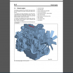
5.1 Diesel engine 66
5.2 Engine description TCD 2012 67
5.3 Lubrication oil circuit TCD 2012 / 2013 69
5.4 Coolant circuit TCD 2012 / 2013 70
5.5 Fuel system TCD 2012 / 2013 71
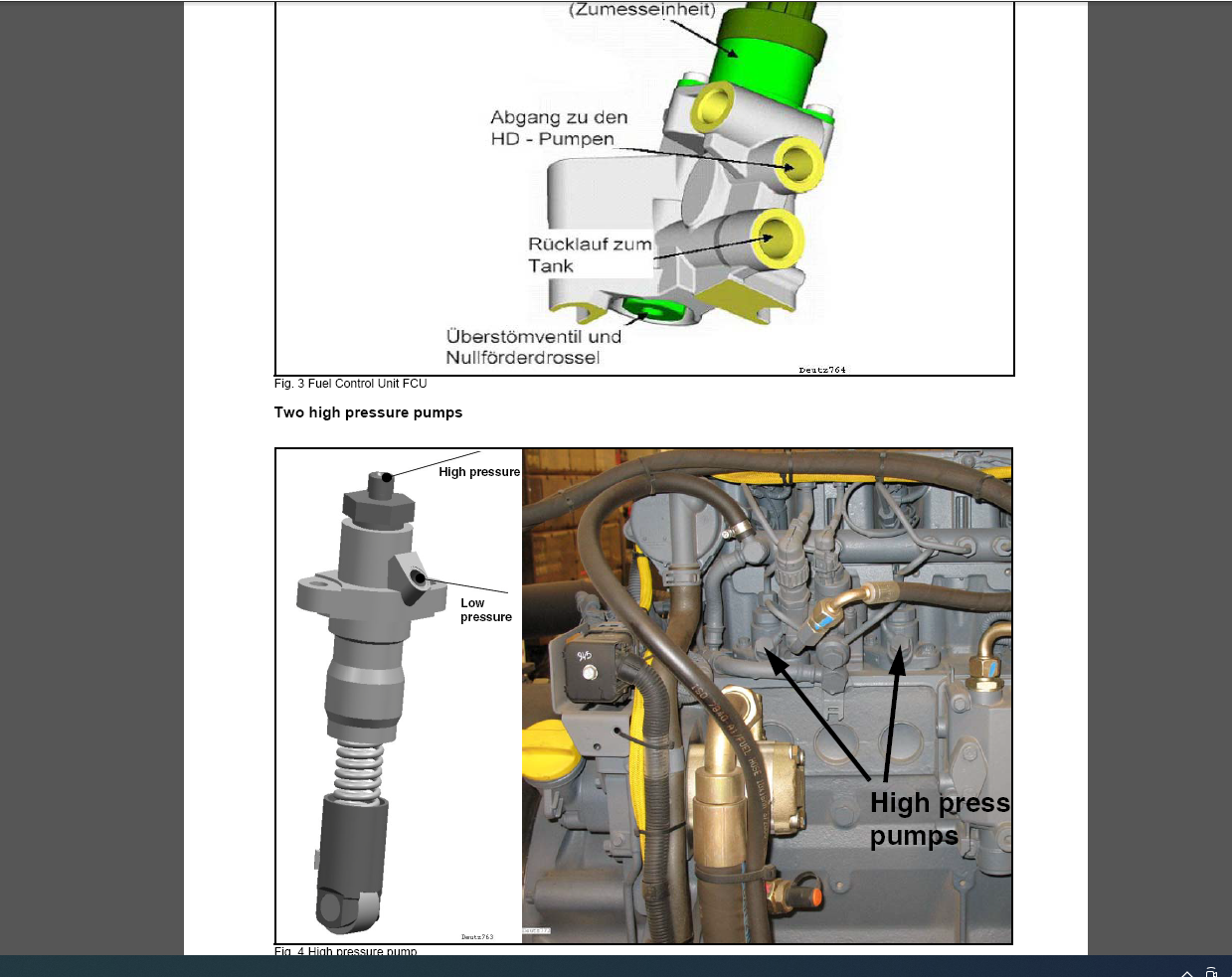
5.6 Deutz Common Rail (DCR) injection system for TCD 2012 / 2013 73
5.7 Exhaust gas recirculation TCD 2012 / 2013 77
5.8 Wastegate – charge pressure controller on TCD-engines 78
5.9 Engine problems 80
5.10 Checking the engine oil level 83
5.11 Changing engine oil and oil filter cartridge 83
5.12 Replacing the fuel pre-filter cartridge, bleed the fuel system 84
5.13 Replace the fuel filter 86
5.14 Check, clean the water separator 87
5.15 Check the coolant level 88
5.16 Replace the coolant 88
5.17 Checking the thermostat in disassembled state 89
5.18 Air filter maintenance 90
5.19 Clean the cooling fins on engine and hydraulic oil cooler 92
5.20 Intercooler, drain off oil and condensation water 93
5.21 Adjust the valve clearance 93
5.22 Checking the ribbed V-belt, replacing if necessary 94
5.23 Replace the crank case ventilation valve 95
5.24 Engine conservation 96
5.25 Special tools, Deutz engine (TCD 2012 2V) 97
Engine electrics 113
Table of Contents
6.1 EMR3 system components 114
6.2 Deutz EMR 3 – engine connections 119
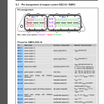
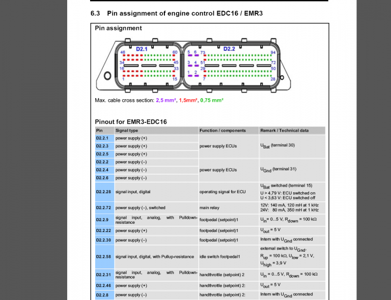
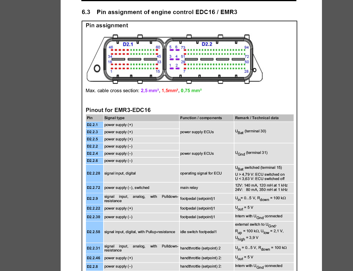
6.3 Pin assignment of engine control EDC16 / EMR3 120
6.4 Rotary speed sensor for camshaft 125
6.5 Crankshaft speed sensor 126
6.6 Rail pressure sensor 127
6.7 Fuel pressure sensor 128
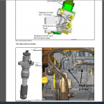
6.8 Fuel control unit 130
6.9 Injector 131
6.10 Oil pressure sensor 132
6.11 Sensor for charge air temperature and charge air pressure 134
6.12 EMR coolant temperature sensor 136
6.13 Glow plugs 138
6.14 Sensor, water in fuel 138
6.15 Air filter vacuum switch 139
6.16 Float switch, coolant tank 140
6.17 Charge control light, engine RPM-meter 141
6.18 Diagnose with SERDIA 142
6.19 Diagnose with CAN-bus 145
6.20 Diagnostics interface 146
6.21 EMR3 List of fault codes 148
6.22 Generator 219
6.23 Replacing the voltage regulator 228
6.24 Electric starter 230
Electrics 237
7.1 Service the battery, check the main battery switch 238
7.2 Starting the engine with jump leads 239
7.3 Starting with jump wires 239
7.4 Fuses 240
7.5 Fuse assignment 241
7.6 Component overview – Electrics 244
7.7 Overview of wiring looms 252
7.8 Control elements 265
7.9 View of control panel 266
7.10 Instrument cluster 268
7.11 Data collector 270
7.12 View of external operator stations 274
7.13 View of external operator stations 275
7.14 View of screed control panel 276
7.15 View of electric heating control panel 277
7.16 Functional block diagram overview of functions, complete 278
7.17 Block diagram components on CAN 279
7.18 Block diagram CAN with control elements 280
7.19 Block diagram of travel circuit 281
7.20 Block diagram material feed 282
7.21 Block diagram screed 283
7.22 Block diagram screed heating 284
7.23 Functional block diagram monitoring functions 285
Table of Contents
008 919 92 BOMAG 5
7.24 Block diagram Emergency Stop functions 286
7.25 Electronic control units 287
7.26 Checking the voltage supply for the control unit 289
7.27 Diagnostics concept 297
Error codes — general information 301
8.1 Error codes – BF800 — general information 302
Input codes 305
9.1 Input codes — Display: Function and operation 306
9.2 Input codes — automatic calibration of currents in the travel system 307
9.3 Input codes — manual calibration of currents in the travel system 310
9.4 Input codes — travel signal by push button for max. screed relief 313
9.5 Input codes — Changing the type of speed potentiometer 315
9.6 Input codes — Activating/deactivating the screed heat in low idle speed 316
9.7 Input codes — activate/deactivate the cleaning function 317
9.8 Input codes — Saving/loading TCU settings 318
9.9 Input codes — Teaching L.C.S. Function 319
9.10 Input codes — changing the tamper start and stop ramps 321
9.11 Input codes — Changing the currents for the tamper pump 324
9.12 Input codes — changing the tamper start and stop ramps 327
9.13 Input codes — Changing the currents for the vibration pump 330
9.14 Input codes — Saving/loading SCU settings 333
9.15 Input codes — Restoring factory settings of the SCU 334
9.16 Input codes — Activate/deactivate hydraulic front gate 335
9.17 Input codes — Changing the currents in the auger pumps 336
9.18 Input codes — Change the auger start / stop ramps 339
9.19 Input codes — Changing the currents in the scraper belt pumps 342
9.20 Input codes — Enable/disable lifting the auger block together with the screed
345
9.21 Input codes — Saving/loading MCU settings 346
9.22 Input codes — Restoring factory settings of the MCU 347
9.23 Input codes — driving against the closed brake 348
9.24 Input codes — showing logged errors 349
9.25 Input codes — showing logged errors with operating hours 350
9.26 Input codes — deleting the error log 351
Replacement of components 353
10.1 How to proceed when replacing components? 354
Material hopper, description 355
11.1 Material hopper and transport 356
Vibrating screed, description 363
12.1 Screed 364
Basic settings on the screed 369
13.1 Notes on the screed adjustment (type S500 & S600) 370
13.2 Bringing the straight crossfalls to zero position 371
13.3 Aligning basic screed and mobile sections 372
Assembling the screed extensions 375
14.1 Notes on assembling screed extensions 376
14.2 Assembling the screed extensions 379
Table of Contents
6 BOMAG 008 919 92
Electric screed heating, repair 391
15.1 Electric screed heating 392
15.2 Electric screed heating – commissioning 397
15.3 Faults in the electric heating 399
Travel drive, description 401
16.1 Travel system 402
Hydraulics 407
17.1 Hydraulic circuit 408
17.2 Component overview — hydraulics 410
17.3 Description of travel pump 415
17.4 View of the machine 421
17.5 Pumps for: Scraper belt, augers, vibration & tampers 422
17.6 View of the machine 429
17.7 Description of fan pump 431
17.8 View of the machine 435
17.9 Description of charge pumps 436
17.10 Check the hydraulic oil level 438
17.11 Change hydraulic oil and hydraulic oil filter 439
Hydraulics – travel circuit 443
18.1 Description of driving 444
18.2 Description of brake circuit 446
Hydraulics – material transport 449
19.1 Description of scraper belts 450
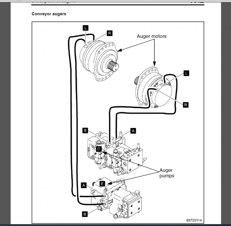
19.2 Description of augers 451
19.3 Description tamping 452
19.4 Description vibration 453
Hydraulics – Service 455
20.1 Description of fan circuit 456
20.2 Description of Service (a) 457
20.3 Description of Service (b) 458
20.4 Description of Load Control System (LCS) 459
Tests and adjustments 461
21.1 Special tools, tests and adjustments 462
21.2 Checking and adjusting the vibration 466
21.3 Checking/adjusting tamping 473
21.4 Checking/adjusting the scraper belts 484
21.5 Checking/adjusting the augers 491
21.6 Checking & adjusting the service pump/cylinder functions 497
21.7 Checking & adjusting the time for screed levelling 501
21.8 Checking/adjusting the hopper wings 503
21.9 Checking/adjusting the mobile screed 505
Circuit diagrams 507
22.1 Hydraulic diagram 509
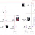
22.2 Electric circuit diagrams


