Bomag Cold Milling Machine BM 2000-60 Service Manual
Bomag Cold Milling Machine BM 2000-60 Service Training
Bomag Cold Milling Machine BM 2000-60 Wiring Diagram
Bomag Cold Milling Machine BM 2000-60 Error Code
Format: PDF
Language: EN
Size:68.7
Pages:10.90
$ 50 Original price was: $ 50.$ 40Current price is: $ 40.
BOMAG BM 2000/60 Service Manual Cold Milling Machine
Bomag Cold Milling Machine BM 2000-60 Service Manual
Bomag Cold Milling Machine BM 2000-60 Service Training
Bomag Cold Milling Machine BM 2000-60 Wiring Diagram
Bomag Cold Milling Machine BM 2000-60 Error Code
index
1.1 Introduction 10
1.2 Safety regulations 11
1.3 General repair instructions 15
1.4 Tightening torques 25 Technical data 29
2.1 Technical data 30 Maintenance 35
3.1 General notes on maintenance 36
3.2 Fuels and lubricants 37
3.3 Table of fuels and lubricants 39
3.4 Running-in instructions 40
3.5 Maintenance table 41 Electrics 45
4.1 Understanding wiring diagrams 46
4.2 Terminal designations in wiring diagram 53
4.3 Circuit symbols in the circuit diagram 55
4.4 Battery ground and analog ground 56
4.5 Processor signals 56
4.6 Current and voltage 57
4.7 Pulse width modulation, PWM 59
4.8 Characteristic of PWM solenoid valves 61
4.9 Resistance 62
4.10 Series / parallel connection 64
4.11 Ohm’s law 66
4.12 Electrical energy 66
4.13 Formula diagram 67
4.14 Metrology 68
4.15 Diodes, relays, fuses 72
4.16 Inductive proximity switches 75
4.17 Plug connectors 76
4.18 Magnetic coil plug 77
4.19 Deutsch plug, series DT and DTM 79
4.20 Telemecanique switch 86
4.21 Plugs and terminals in spring clamping technology 89
4.22 Batteries 93
4.23 Battery maintenance 95
4.24 Main battery switch, 150S1 96
4.25 Fuses in battery compartment 97
4.26 CAN BUS overview 98
4.27 ID nodes, overview and fusing 100
4.28 Control panels operator’s stand, 106B1, 106B2 and 106B3 101
4.29 Modules CR2012, operating consoles 108
4.30 Fuse, multi-function display 109
4.31 Control panel contact pressure, 100B10 and 100B11 110
4.32 Control console for auxiliary control 100B5 111
Table of Contents
BOMAG BM 2000/60 Service Manual
4 BOMAG 008 915 97
4.33 Control panel, 100B9 112
4.34 Control panel rear right, 100B3 and 100B8 114
4.35 Control panel rear left, 100B2 and 100B7 116
4.36 Control panel front right, 100B4 118
4.37 Control console front left, 100B1 120
4.38 Central electrics, 106.1B1 122
4.39 Modules CR2012, central electrics 126
4.40 Travel pump high pressure sensor, 290.1S2 127
4.41 Hydraulic oil temperature sensor, 290.1S1 136
4.42 Water sprinkling system 147
4.43 Limit switch on scraper, 214.2S1 and 214.2S2 150
4.44 Rope sensors for height control, 226.5R2 and 226.5R1 152
4.45 Rope sensors for steering, 264.6R1 and 264.6R.2 155
4.46 Proximity switches, height limitation 156
4.47 Valve block (working valve) 158
4.48 Pressure sensor for conveyor belt drive, 290.1S3 161
4.49 Temperature control valve for fan circuit, 216Y1 163
4.50 Fan circuit pressure sensor, 290.1S4 165
4.51 Clutch pressure sensor, 290.2S1 167
4.52 Pressure sensor for the scraper flap, 290.2S4 169
4.53 Pressure sensor for hold-down, 290.2S3 171
4.54 Pressure sensor for working hydraulics, 290.2S2 173
4.55 Hydraulic temperature switch, 290S4 175
4.56 Hydraulic oil filter differential pressure switch, 290S1 to 290S3 177
4.57 Coolant level sensors, 170.1S2 and 170.1S4 179
4.58 Travel speed sensor 206.7S1 181
4.59 Solenoid valve travel pump, 206.7Y1 183
4.60 Solenoid valve differential lock, 206.6Y2 184
4.61 Solenoid valve brake, 206.6Y3 186
4.62 Solenoid valve speed range selection, 206.6Y1 187
4.63 Solenoid valve conveyor belt pump, 238.9Y1 189
4.64 Modules in engine compartment, CR2031 191
4.65 Module, CR2031 192
4.66 Module CR2012 196
4.67 Electronic control units 200
4.68 Machine control CR0505 201 CAN-Bus, Parameter and Diagnose 205
5.1 CAN BUS overview 206
5.2 ID nodes, overview and fusing 208
5.3 ID-nodes, inputs 209
5.4 ID-nodes, outputs 214
5.5 Multi-function display 217
5.6 Error messages, multi-function display 219
5.7 Multi-function display, setup 220
5.8 Adjustment parameters overview 224
5.9 Menu option, Tuning Parameters 225
5.10 Menu option, Check Input Output 226
5.11 Menu option, Display Adjustment 228
Table of Contents
008 915 97 BOMAG 5
5.12 Menu option, Can-Bus 229
5.13 Menu option, Machine States 230
5.14 Menu option, RS232 232
5.15 Side Doors, Setup 232
5.16 Milling Drum 234
5.17 Steering, Joysticks 235
5.18 Steering, Pistons 236
5.19 Steering, Adjust Potentiometer 237
5.20 Steering, Central Position Calibration 238
5.21 Steering, Pistons Position Limit 239
5.22 Steering, Front-Rear link 240
5.23 Steering, Front Prop. Solenoid Valve 241
5.24 Travelling, Joysticks Potentiometer 242
5.25 Travelling, Softgear 243
5.26 Travelling, Engine Load Manager 243
5.27 Travelling, Time Ramps 244
5.28 Travelling, Var. displ. pump 245
5.29 Travelling, Var. displ. motor 246
5.30 Pause, Time In Sequence 247
5.31 Pause, Time Out Sequence 248
5.32 Columns, Levelling Wire Sensor 249
5.33 Columns, Levelling Slope Sensor 250
5.34 Columns, Speed 251
5.35 Columns, Calibration Levelling Sensor 252
5.36 Columns, Left Column Prop. Valve 253
5.37 Columns, Right Column Prop. Valve 254
5.38 Conveyor, Potentiometer 255
5.39 Conveyor, Var. Displ. Pump 256
5.40 Backdoor, Set-Up 257
5.41 Backdoor, Solenoid Valve 257
5.42 Fan 258
5.43 Fan, Solenoid Valve 259
5.44 Check Input Output, ID-node CR0505 260
5.45 Check Input Output, ID-node CR2012 262
5.46 Check Input Output, ID-node CR2012 265
5.47 Can Bus, Scan 269
5.48 Can Bus, Change Node ID 270
5.49 ID nodes, overview and fusing 271
5.50 Machine States, Page 400 272
5.51 Machine States, Page 401 275
5.52 Machine States, Page 402 277 Engine electrics 281
6.1 Engine control unit 282
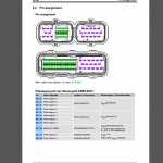
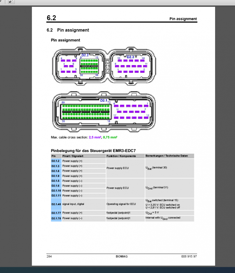
6.2 Pin assignment 284
6.3 Diagnose with SERDIA 290
6.4 CAN BUS overview 293
6.5 Diagnose with CAN-bus 295
6.6 Error messages, multi-function display 295
Table of Contents
6 BOMAG 008 915 97
6.7 Diagnostic interface, XMB 297
6.8 EMR3 List of fault codes 299
6.9 Sensors 370
6.10 Oil pressure sensor 372
6.11 Fuel temperature sensor 375
6.12 Charge air temperature – charge air pressure sensor 377
6.13 Coolant temperature sensor 380
6.14 Coolant level sensors, 170.1S2 and 170.1S4 383
6.15 Speed sensor for diesel engine 385
6.16 Preheating system 388
6.17 Sensor, water in fuel, 170.1S3 390
6.18 Air filter vacuum switch, 170.1S1 391
6.19 Generator 392
6.20 Replacing the voltage regulator 402
6.21 Electric starter 404 Engine 411
7.1 Diesel engine 412
7.2 Engine description TCD 2015 V 8 cylinder 413
7.3 Lubrication oil circuit TCD 2015 415
7.4 Coolant circuit TCD 2015 416
7.5 Fuel circuit TCD 2015 417
7.6 Injection system (MVS) TCD 2015 420
7.7 Exhaust gas recirculation TCD 2015 422
7.8 Wastegate – charge pressure controller on TCD-engines 423
7.9 Adjusting the valve clearance 425
7.10 Check the engine oil level 426
7.11 Changing engine oil and oil filter cartridges 427
7.12 Check the coolant level 428
7.13 Change the coolant 429
7.14 Checking the thermostat in disassembled state 429
7.15 Cleaning the engine 430
7.16 Check, clean the water separator 431
7.17 Change the fuel pre-filter cartridge 431
7.18 Change the fuel filter cartridge 433
7.19 Checking, replacing the generator V-belt 434
7.20 Service the combustion air filter 435
7.21 Intercooler, draining oil and condensation water 437
7.22 Check fastening of engine / turbocharger / combustion air hoses 437
7.23 Engine conservation 438
7.24 General trouble shooting chart TCD 2015 439
7.25 Special tools, Deutz engine (TCD 2015) 441 Milling drive, mechanics 461
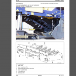
8.1 Milling drive 462
8.2 Checking, replacing the milling drum V-belt 475
8.3 Change the oil in the milling drum reduction gear 476
8.4 Oil change in milling drum bearing 476
8.5 Checking/replacing cutting tools, scraper 477
8.6 Replacing bases/holders 480
Table of Contents
008 915 97 BOMAG 7
8.7 Lubricating the milling drum 481
8.8 Lubricating the dry clutch 481
8.9 Checking the wear of the friction lining 482
8.10 Friction lining / replacing the outer discs 482 Conveyor belts, mechanics 487
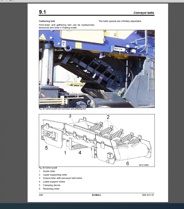
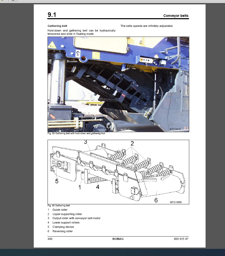
9.1 Conveyor belts 488
9.2 Checking, tightening the conveyor belts 492
9.3 Checking the safety ropes 493
9.4 Lubricating the conveyor belts 493
9.5 Folding / unfolding the loading conveyor belt 495 Travel drive, mechanics 497
10.1 Travel drive 498
10.2 Checking the track plates 502
10.3 Retightening the track shoe fastening screws 502
10.4 Checking the track drive 503
10.5 Lubricating the travel drive 505
10.6 Lubricating the steering system 505
10.7 Oil change in track drive gear 506 Pump transfer case 507
11.1 Transfer case 508
11.2 Check the oil level in the pump drive gear 511
11.3 Change the oil in the pump drive gear 511 Hydraulics 513
12.1 Service Training BOMAG Road Milling Machines – Hydraulics 514
12.2 Fault display 517
12.3 Travel System – Service Training 522
12.4 Conveyor belt drive 553
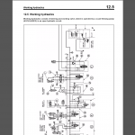
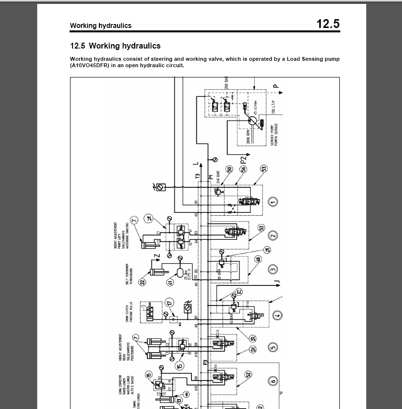
12.5 Working hydraulics 559
12.6 Fan drive 569
12.7 Electric pump for auxiliary control (additional valves) 575 Suppliers documentation 581
13.1 Steering and working pump 583
13.2 Travel pump 613
13.3 Conveyor belt pump 715
13.4 Travel motor 773
13.5 Travel gear 827
13.6 Conveyor belt motor 897
13.7 Sprinkling pump 915 Circuit diagrams 939
14.1 Hydraulic diagram B2630030 941
14.2 Wiring diagram DE012004
