BM 1000/30-2/1200/30-2/1300/30-2 SERVICE MANUAL
BM 1000/30-2_PB/1200/30-2_PB/ 1300/30-2_PB SERVICE MANUAL
BOMAG Cold Milling Machine BM 1000/30-2 Service Manual PDF
BOMAG Cold Milling Machine BM 1000/30-2 Service Training
BOMAG Cold Milling Machine BM 1000/30-2 Wiring diagram ( electric diagrams ) – Hydraulic Diagram
Format: PDF
Language : EN – RU
Size: 73.5 mb
$ 50 Original price was: $ 50.$ 40Current price is: $ 40.
BOMAG BM1200/30-2 Service Manual
1.1 Introduction 8
1.2 Safety regulations 9
1.3 General repair instructions 13
1.4 Tightening torques 23 Technical data 27
2.1 Technical data 28 Maintenance 37
3.1 Fuels and lubricants 38
3.2 Running-in instructions 40 Electrics 41
4.1 Designation of components in the wiring diagram 42
4.2 Terminal designations in wiring diagram 43
4.3 Battery ground and analog ground 45
4.4 Current and voltage 45
4.5 Pulse Width Modulation (PWM) 48
4.6 Logical base gates 50
4.7 Resistance 53
4.8 Series / parallel connection 55
4.9 Ohm’s law 57
4.10 Electrical energy 57
4.11 Formula diagram 58
4.12 Metrology 59
4.13 Diodes, relays, fuses 63
4.14 Telemecanique switch 66
4.15 Plug connectors 68
4.16 Magnetic coil plug 68
4.17 Deutsch plug, series DT and DTM 70
4.18 Plugs and terminals in spring clamping technology 75
4.19 Inductive proximity switches 79
4.20 Batteries 80
4.21 Battery service 84
4.22 Starting with jump wires 85
4.23 Main fuse 86
4.24Fuses 86
4.25 Component overview 88
4.26 Control elements 89
4.27 View of operator’s stand 89
4.28 View rear right hand control panel (B4) 90
4.29 View rear left hand control panel (B3) 91
4.30 View front right hand control console (B7) 92
4.31 View front left hand control console (B5) 93
4.32 View control panel for auxiliary control / limp home control (B10) 94
4.33 Multi-function display (MFD) 95
4.34 Levelling control console, general 97
4.35 Levelling control console, description 98
Table of Contents
4 BOMAG 008 917 61
4.36 Viewing switching states of switches and valves 100
4.37 Work parameters for engine load and height control 104
4.38 Rope sensors for height control, C22 and C24 109
4.39 Operating conditions for height regulation 110
4.40 Rope sensor, front steering, 264R1 116
4.41 Cable sensor, rear steering, C16 117
4.42 Operating conditions for rear steering 119
4.43 Height limitation, rear 125
4.44 Operating conditions for rear posts 126
4.45 Limit switch on scraper, C48 and C49 128
4.46 Functional conditions for scraper 130
4.47 Water sprinkling system 133
4.48 Operating condition for sprinkling system 135
4.49 Differential pressure switch for hydraulic oil 136
4.50 Speed sensor, C53 138
4.51 Operating conditions for travel drive 140
4.52 Functional conditions for hold-down 148
4.53 Functional conditions right side plate 150
4.54 Functional conditions for milling drum drive 152
4.55 Functional conditions for conveyor belts 153
4.56 Engine speed sensor, C8 155
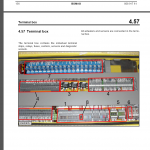
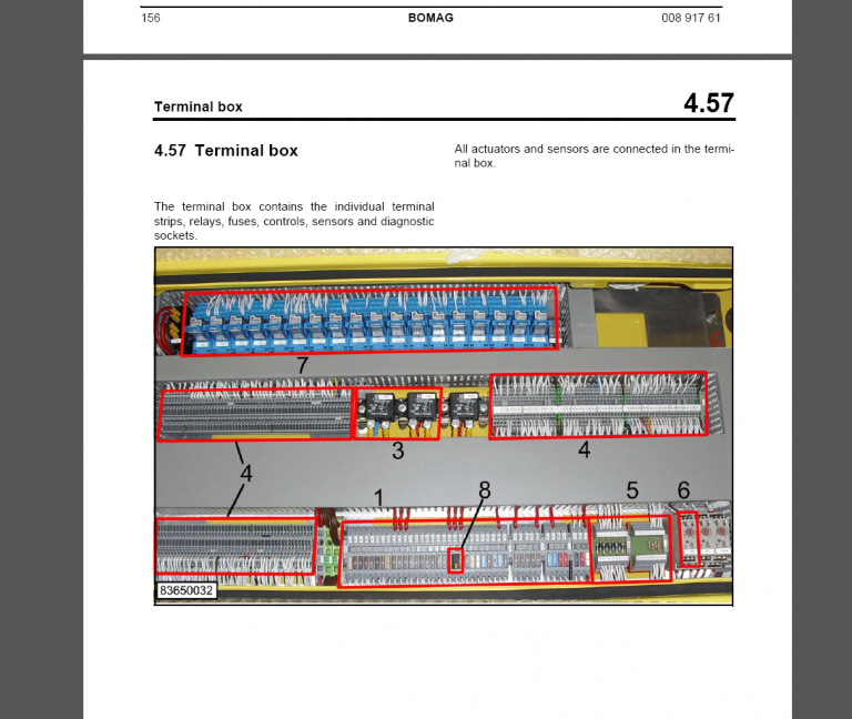
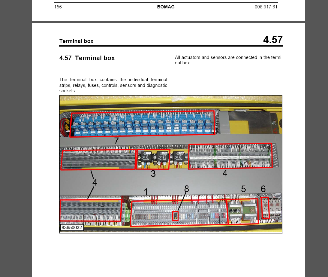
4.57 Terminal box 157
4.58Fuses 160
4.59 Pin assignment for control 161
4.60 Generator 163
4.61 Generator repair 168
4.62 Electric starter 172
4.63 Repair of starter 178 Engine 183
5.1 General information on diesel engine 184
5.2 Engine attachment parts 186
5.3 Engine electrics 188
5.4 Checking the cylinder head ground cable 192
5.5 Engine diagnostics lamps, H8 and H9 193
5.6 General notes on flashing codes 195
5.7 Table of flashing codes 196
5.8 Check the engine oil level 197
5.9 Change engine oil and oil filter cartridge 198
5.10 Check, clean the water separator 199
5.11 Change the fuel pre-filter cartridge 199
5.12 Replace the fuel filter cartridge 200
5.13 Checking the combustion air filter 201
5.14 Service the combustion air filter 202
5.15 Check the coolant level 204
5.16 Checking the condition of the coolant hoses 204
5.17 Change the coolant 205
5.18 Clean the cooling fins on engine and hydraulic oil cooler 205
5.19 Checking, tensioning the V-belt for the generator system 206
Table of Contents
008 917 61 BOMAG 5
5.20 Cleaning the crankcase ventilation 207
5.21 Check the engine mounts 207
5.22 Checking the valve clearance 208
5.23 Engine problems 209 Milling drive, description 213
6.1 Milling drive 214 Milling drive, repair 223
7.1 Checking, replacing the milling drum V-belt 224
7.2 Change the oil in the milling drum reduction gear 225
7.3 Oil change in milling drum bearing 225
7.4 Lubricating the milling drum 226
7.5 Lubricating the dry clutch 226 Milling drum, repair 227
8.1 Repair overview milling drum 228
8.2 Replacing tool holders 229
8.3 Check/replace cutting tools, scraper 230 Milling unit, description 235
9.1 Description of milling unit 236 Travel drive, description 245
10.1 Travel system 246 Travel drive, repair 251
11.1 Checking the track plates 252
11.2 Retightening the track plate fastening screws 252
11.3 Check the track drive 253
11.4 Lubricating the travel drive 256
11.5 Lubricating the steering system 257
11.6 Lubricating the posts 258
11.7 Oil change in track drive gear 259 Conveyor belt, description 261
12.1 Conveyor belts 262
12.2 Folding / unfolding the loading conveyor belt 265 Conveyor belt, repair 267
13.1 Checking, tightening the conveyor belts 268
13.2 Checking the safety ropes 269
13.3 Lubricating the conveyor belts 270 Hydraulics 273
14.1 Hydraulic circuit 274
14.2 Component overview — hydraulics 276
14.3 Description of travel pump 279
14.4 View of the machine 286
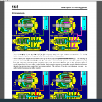
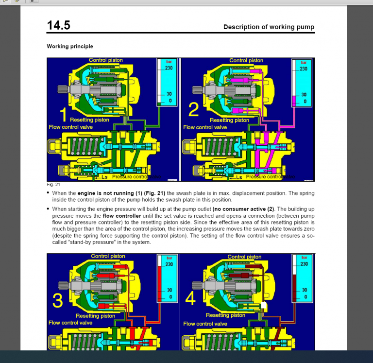
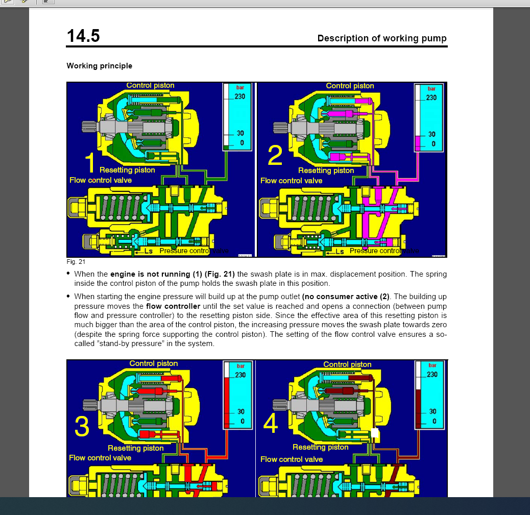
14.5 Description of working pump 287
14.6 View of the machine 291
14.7 Description of conveyor belt pump 292
14.8 View of the machine 299
14.9 Troubleshooting axial piston pumps 301
14.10 Description of fan pump 304
14.11 View of the machine 306
Table of Contents
6 BOMAG 008 917 61
14.12 Desxcription of travel motor BOSCH REXROTH 307
14.13 View of the machine 309
14.14 Check the hydraulic oil level 310
14.15 Clean the cooling fins on engine and hydraulic oil cooler 310
14.16 Changing hydraulic oil and breather filter 311
14.17 Changing the hydraulic oil filter 312 Hydraulics – travel circuit 313
15.1 Description of driving 314
15.2 Description of crawler system 315
15.3 Description of steering 316 Hydraulics – milling operation 319
16.1 Description of clutch 320
16.2 View of the machine 321
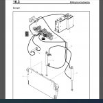
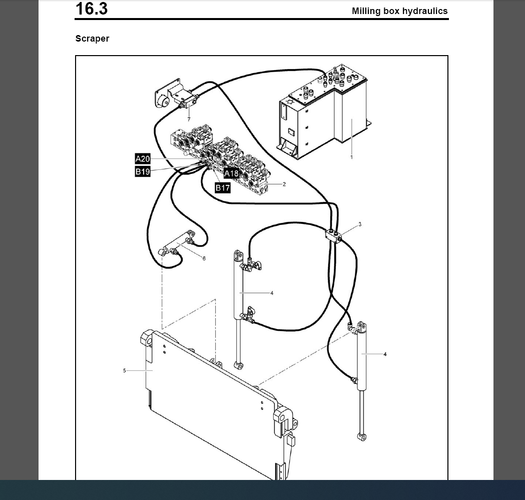
16.3 Milling box hydraulics 322
16.4 View of the machine 325 Hydraulic cylinder 329
17.1 Repairing hydraulic cylinders 330 Tests and adjustments 333
18.1 Special tools, tests and adjustments 334
18.2 Checking/adjusting the travel pump 338 Suppliers documentation 343
19.1 Steering/working pump 345
19.2 Travel pump 371
19.3 Conveyor belt pump 409
19.4 Travel motor 467
19.5 Milling drive 521
19.6 Travel gear 595
19.7 Conveyor belt motor 651
19.8 Sprinkling pump 669
19.9 Steering valve 693
19.10 Clutch – milling drive 727 Circuit diagrams 747
20.1 Hydraulic diagram 749
20.2 Electric circuit diagrams
