BOMAG BW 211D-40 SERVICE MANUAL
Bomag Single drum roller BW 211D-40 Service Training PDF
Single drum roller BW 211D-40 Wiring Diagrams
Bomag BW 211D-40 Single drum roller PDF manual repair
Format: PDF
Language: En –
Size:120 MB
$ 50 Original price was: $ 50.$ 40Current price is: $ 40.
BOMAG BW 211D-40 Service Manual Pdf
Bomag Single drum roller BW 211D-40 Repair Manual , Wiring Diagram,
Introduction 8
Safety regulations 9
General repair instructions 14
Tightening torques 26 Technical data 31
Technical data 32 Maintenance 41
General notes on maintenance 42
Fuels and lubricants 43
Table of fuels and lubricants 47
Running-in instructions 48
Maintenance chart 49 Connection overview 51
Connection overview 52 Tests and adjustments 55
Special tools, tests and adjustments 56
Checking the rotation speeds 60
Checking / adjusting the neutral positions of the travel pump 62
Pressure tests in the travel circuit 64
Checking / adjusting the vibrator shaft speeds 66
5.6 Pressure measurements in the vibration circuit 67
Check the leakage rate of the vibration motor 68
Pressure test in steering circuit 69 Flushing and bleeding 71
Special tools for flushing 72
Flushing – general 77
Flushing schematic travel circuit (distribution travel pump) 79
Flushing the travel circuit (travel pump distribution) 81
Flushing schematic travel circuit (distribution axle motor) 87
Flushing the travel circuit (axle motor distribution) 92
Flushing schematic for vibration drive 97
Flushing the vibration circuit 98
Bleeding the travel circuit 102
Bleeding the vibration circuit 104 Caddy wiring diagrams 107
7.1 Understanding circuit diagrams 108
7.2 Circuit symbols in the circuit diagram 113
7.3 Identification of switch blocks in the Caddy wiring diagram 114 E-Plan wiring diagrams 115
8.1 Understanding wiring diagrams 116
8.2 Circuit symbols in the circuit diagram 125
8.3 Identification of switch blocks in the wiring diagram 128 Electrics 129
9.1 Designation of components in the wiring diagram 130
9.2 Terminal designations in wiring diagram 131
Table of Contents
4 BOMAG 008 911 63
Battery ground and analog ground 133
Current and voltage 133
Resistance 135
Series / parallel connection 137
Ohm’s law 139
Electrical energy 140
Formula diagram 141
Metrology 142
Diodes, relays, fuses 146
Telemecanique switch 149
Plug connectors 152
Magnetic coil plug 153
Deutsch plug, series DT and DTM 155
Plugs and terminals in spring clamping technology 160
Inductive proximity switches 164
Angle sensors 165
Acceleration transducer 168
Batteries 169
Battery maintenance 174
Main battery fuse 175
9.23 Starting with jump wires 175
9.24 Generator 176
9.25 Replacing the voltage regulator 185
9.26 Electric starter 187
9.27 Operator’s stand, old design 193
9.28 Operator’s stand, new design 195
9.29 Cabin 197
9.30 Fuses, old design 198
9.31 Fuses, new design 199
Electronic control units 200
Checking the voltage supply for the control unit 203
Diagnostics concept 211 582 502 15 dust protection / 582 502 16 gasket 215
Assembling the dust protection 216 Electronic modules 221
BEM, BOMAG Evib-meter 223
Electrics module A68 287
Electric module K04 295
Electric module A72 299
Electric module A108 305 Speedometer Module 309
Speedometer module 310 Service Training 313
Service Training 315 Engine 379
Diesel engine, general 380
14.2 Service side 381
Table of Contents
008 911 63 BOMAG 5
Starter side 382
Lubrication oil circuit 383
Oil pressure switch and low oil pressure circuitry 385
14.6 Check the engine oil level 386
14.7 Changing engine oil and oil filter cartridges 387
14.8 Coolant circuit 389
14.9 Coolant temperature switch 391
14.10 Disassembling and assembling the coolant temperature switch 392
14.11 Replacing the thermostat 393
14.12 Checking the thermostat in disassembled state 394
14.13 Check the coolant level 395
14.14 Change the coolant 395
14.15 Checking the anti-freeze concentration 396
14.16 Clean the cooling fins on engine and hydraulic oil cooler 397
14.17 Three-phase generator 398
14.18 Fuel supply 400
14.19 Injection system 403
14.20 Injection pump replacement during service 404
14.21 Injection valve replacement during service 413
14.22 Checking / repairing injection valves 416
14.23 Fuel filter 421
14.24 Check, clean the water separator 423
14.25 Change the fuel pre-filter cartridge 423
14.26 Change the fuel filter cartridge 425
14.27 Checking the compression 425
14.28 Check, adjust the valve clearance 426
14.29 Boost fuel solenoid valve 428
14.30 Engine shut-down solenoid 429
14.31 Air filter 430
14.32 Cleaning, changing the dry air filter cartridge 431
14.33 Heating flange on engine 433
14.34 Checking the heating flange control 436
14.35 Electric throttle control 437
14.36 Engine monitoring 439
14.37 Engine 442
14.38 Special tools, Deutz engine (BFM 2012) 444 Air conditioning system 457
15.1 Physical basics 458
15.2 Refrigerant R134a 461
Compressor oil / refrigeration oil 462
Working principle of the air conditioning system 463
Monitoring devices 463
Description of components 464
Measuring the compressor oil level 470
Checking the magnetic clutch 470
Inspection and maintenance work 471
Checking, replacing the refrigerant compressor V-belt 472
Air conditioning service (old design) 473
Table of Contents
6 BOMAG 008 911 63
15.12 Service the air conditioning 475
15.13 Drying and evacuation 478
15.14 Emptying in case of repair 478
15.15 Leak test 479
15.16 Filling instructions 480
15.17 Trouble shooting in refrigerant circuit, basic principles 483
15.18 Trouble shooting, refrigerant circuit diagram 487
15.19 Trouble shooting procedure 488
15.20 Steam table for R134a 498 Cabin assembly 503
16.1 Preparations 505
16.2 Cabin assembly 506
16.3 Final function tests and checks 511 Replacing the cab window panes 513
17.1 Assembly of window panes 514
17.2 Special tools, cabin windows 515
17.3 Auxiliary materials 516
17.4 Removing and installing the window pane 518 Drum 523
18.1 Special tools, drum, single drum rollers 524
18.2 Repair overview for drum 526
18.3 Removing and installing the drum 533
18.4 Repairing the drum 538
18.5 Disassembling and assembling the change-over weight 571
18.6 Changing the rubber buffers and adjusting the pretension 574 Oscillating articulated joint 577
19.1 Special tools, oscillating articulated joint (BW177 to BW 216) 578
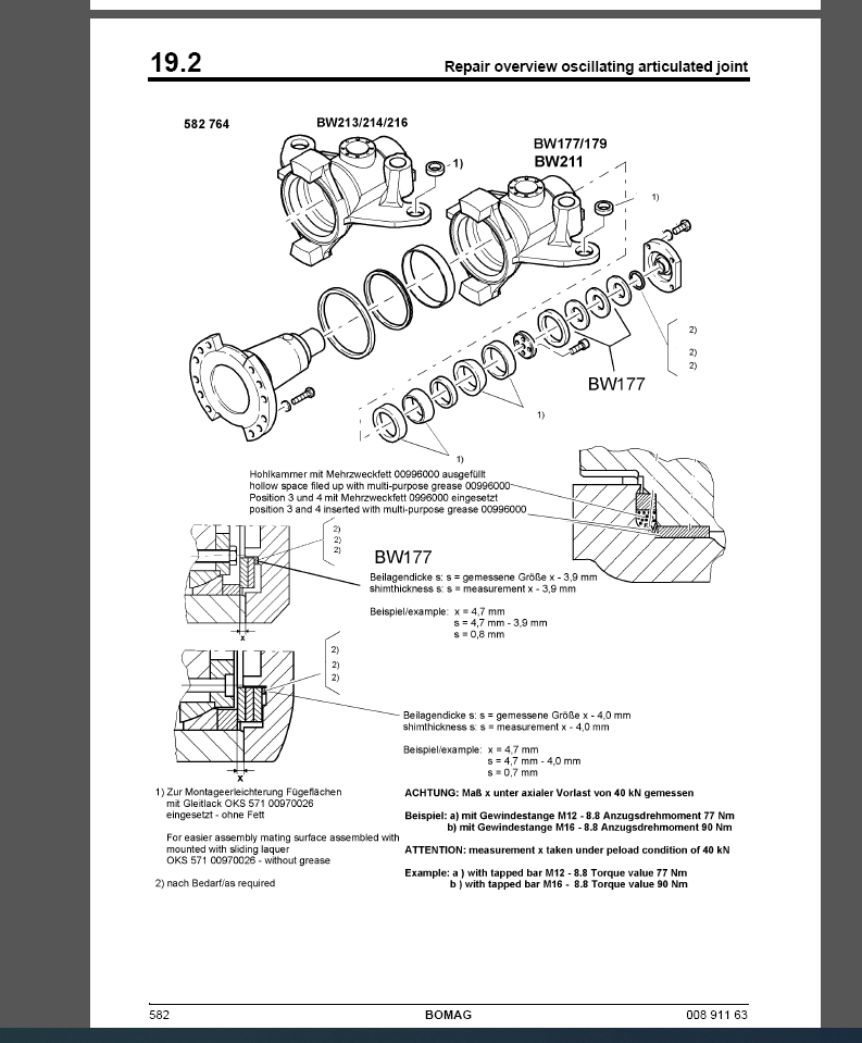
19.2 Repair overview oscillating articulated joint 580
19.3 Removing and installing the oscillating articulated joint 584
19.4 Dismantling the oscillating articulated joint 586
19.5 Assembling the oscillating articulated joint 591 Suppliers documentation 601
20.1 Travel pump 603
20.2 Vibration pump 757
20.3 Drum drive 827
20.4 Vibration motor 903
20.5 Axle drive motor 927
20.6 Steering valve 1009
20.7 Axle 1043 Circuit diagrams 1165
2 Hydraulic diagram 581 202 10 1167
