$ 0
0
$ 0
0

Bobcat 2000 Loader Articulated Service Manual (SN 502111001-502199999)

Format: PDF (Printable Document)

File Language: English

File Pages: 354

File Size: 11.27 MB (Speed Download Link)

Brand: Bobcat

Model: 2000 Loader Articulated

Book No: 6566180

Serial No: SN 502111001-502199999

Type of Document: Service Manual

Categories: ,

$ 45

Share:

Bobcat 2000 Loader Articulated Service Manual (SN 502111001-502199999)

On a real job, a Bobcat 2000 articulated loader is the yard mule and material handler, running around tight sites the way a small Cat or Deere loader would. The service manual is what you grab when you're past basic maintenance and into real repair work. Shops and owner-operators use it when they're chasing hydraulic issues, rebuilding components, or sorting out electrical gremlins. If you're trying to keep a used machine alive without guessing, this is the book you work from.

What this manual helps you do

  • Diagnose hydraulic and hydrostatic problems, then check pressures and flows against Bobcat specs
  • Trace, test, and repair wiring using proper schematics for this 2000 articulated loader
  • Follow teardown and reassembly steps for cylinders, drive components, and major mechanical assemblies
  • Set and verify adjustments on linkages, brakes, steering, and hydraulic controls after repair
  • Troubleshoot engine-related issues as they tie into the loader's systems, sensors, and safety circuits

Who this is for

This is for small contractors, rental fleets, owner-operators, and shop mechanics who are actually wrenching on a Bobcat 2000 Loader Articulated in the listed serial range. If you just need operating instructions or daily service points, you want the operator's handbook instead, not this service manual.

FAQ

Q: Is this a searchable PDF, and can I read the wiring diagrams clearly?

A: These manuals are usually scanned or native PDFs that you can search, zoom, and print, and the wiring diagrams are laid out for screen or paper use.

Q: Does it cover my exact machine?

A: It is meant for Bobcat 2000 Loader Articulated units in serial range 502111001 to 502199999, so you'll want your serial plate to match that range.

Q: Is this the right document if I'm doing real repairs, not just maintenance?

A: Yes, this is the workshop-level service manual, the one you'd use for diagnostics, teardown, and reassembly, not just fluid changes.

Bottom line: If your 2000 articulated loader's serial number falls in 502111001-502199999 and you're doing actual repair work, this is the right manual. If not, skip it.

📘 Show Index

Table of Contents:

  • MAINTENANCE SAFETY
  • CONTENTS
    • FOREWORD
    • SAFETY INSTRUCTIONS
      • Safety Is your Responsibility
      • Before You Operate The Bobcat Loader
      • Safe Operation needs A Qualified Operator
    • FIRE PREVENTION
    • SERIAL NUMBER LOCATIONS
      • Loader Serial Number
      • Engine Serial Number Locations
    • ARRIVAL CONDITION REPORT
    • DELIVERY REPORT
    • BOBCAT LOADER IDENTIFICATION
  • PREVENTIVE MAINTENANCE
    • SERVICE SCHEDULE
    • LIFT ARM STOP
    • FRAME LOCK
    • LIFTING AND BLOCKING THE LOADER
    • REAR DOOR
      • Door Latch Adjustment
    • AIR CLEANER
    • FUEL SYSTEM
      • Filling The Fuel Tank
      • Fuel Filter
      • Removing Air From The Fuel System
    • ENGINE LUBRICATION SYSTEM
      • Engine Oil And Filter Replacement
    • ENGINE COOLING SYSTEM
      • Coolant Level
      • Coolant Replacement
    • ALTERNATOR BELT ADJUSTMENT
    • ELECTRICAL SYSTEM
      • Electrical System Service
      • Using An Extra Battery (Jump Starting)
      • Battery Replacement
    • HYDRAULIC / HYDROSTATIC SYSTEM
      • Hydraulic/Hydrostatic Fluid Reservoir
      • Checking And Adding Fluid
      • Hydraulic Fluid Replacement
      • Hydraulic / Hydrostatic Filter Replacement
    • SPARK ARRESTOR MUFFLER
    • FRONT & REAR AXLES
    • U-JOINTS
    • TIRE MAINTENANCE
      • Wheel Nuts
    • LOADER LUBRICATION
    • BACK-UP ALARM
    • OPERATOR CAB
  • HYDRAULIC SYSTEM
    • HYDRAULIC / HYDROSTATIC SCHEMATICS
    • TROUBLESHOOTING
    • HYDRAULIC SYSTEM INFORMATION
      • 37° Flare Connections
      • Straight Thread O-Ring Fitting
      • Tubelines And Hoses
    • PORT BLOCK SERVICE
      • Bronze (40 Micron) Filter Replacement
      • Neutral By-Pass Valve Replacement
      • Cold Oil By-Pass Valve Replacement
    • OIL RESERVOIR
      • Oil Reservoir Removal
      • Oil Reservoir Installation
    • HYDRAULIC CONTROL VALVE (S/N 12999 & BELOW)
      • Hydraulic Control Valve Removal
      • Hydraulic Control Valve Disassembly
      • Inlet Section
      • Tilt Section
      • Lift Section
      • Auxiliary Section (For Older Style Control Valves)
      • Auxiliary Section (For Control Valves Equipped With Adjustable Detent)
      • Auxiliary Detent Adjustment
      • Hydraulic Control Valve Assembling
      • Hydraulic Control Valve Installation
    • HYDRAULIC CONTROL VALVE (S/N 13001 & ABOVE – MELROE VALVE)
      • Hydraulic Control Valve Removal
      • Hydraulic Control Valve Disassembly
      • Hydraulic Control Valve Inspection
      • Hydraulic Control Valve Assembling
      • Hydraulic Control Valve Installation
    • HYDRAULIC MAIN RELIEF VALVE
      • Hydraulic Main Relief Valve Testing
      • Hydraulic Main Relief Valve Replacement
      • Hydraulic Main Relief Valve Adjustment (S/N 12999 & Below)
      • Hydraulic Main Relief Valve Cleaning (S/N 13001 & Above)
      • Hydraulic Main Relief Valve Adjustment (S/N 13001 & Above)
    • HYDRAULIC PUMP
      • Checking Hydraulic Pump Pressure
      • Hydraulic Pump Removal
      • Hydraulic Pump Disassembly
      • Hydraulic Pump Inspection
      • Hydraulic Pump Assembling
      • Hydraulic Pump Installation
      • Checking Steering Relief Pressure
    • HYDRAULIC CYLINDERS
      • Checking Lift And Tilt Cylinder Seals
      • Checking Steering Cylinder Seals
      • Lift Cylinder Removal
      • Lift Cylinder Installation
      • Tilt Cylinder Removal
      • Tilt Cylinder Installation
      • Steering Cylinder Removal
      • Steering Cylinder Installation
      • Hydraulic Cylinder Disassembly
      • Hydraulic Cylinder Assembly
    • STEERING CONTROL VALVE
      • Steering Control Valve Removal
      • Steering Control Valve Disassembly
      • Steering Control Valve Inspection
      • Steering Control Valve Assembling
      • Steering Control Valve Installation
  • HYDROSTATIC SYSTEM
    • TROUBLESHOOTING
    • SERVO CONTROL
      • Servo Control Neutral Adjustment
      • Servo Control Removal
      • Servo Control Disassembly
      • Servo Control Assembling
      • Servo Control Installation (S/N 13033 & Below)
      • Servo Control Installation (S/N 13034 & Above)
    • FOOT PEDAL, PEDAL LOCK SYSTEM AND CENTERING MECHANISM
      • Foot Pedal Angle Adjustment
      • Seat Bar Assembly (S/N 13092 & Above)
      • Pedal Lock Cable
      • Centering Mechanism Removal
      • Centering Mechanism Spring Adjustment
        • S/N 13091 & Below
        • S/N 13092 & Above
      • Centering Mechanism Spring Replacement
        • S/N 13091 & Below
        • S/N 13092 & Above
      • Centering Mechanism Installation
      • Checking The Neutral Safety Switch
      • Neutral Safety Switch Adjustment
      • Micro Switch Adjustment
    • CHARGE PRESSURE AND REPLENISHING VALVES
      • Checking Charge Pressure
      • Checking Orifice In Charge Tubeline
      • Replenishing Valves
    • HYDROSTATIC PUMP
      • Hydrostatic Pump Removal
      • Hydrostatic Pump Disassembly
      • Hydrostatic Pump Inspection
      • Hydrostatic Pump Assembling
      • Hydrostatic Pump Installation On The Manifold Block
      • Hydrostatic Pump Installation
      • Hydrostatic Pump Start-Up Procedure
    • HYDROSTATIC MOTOR
      • Hydrostatic Motor Removal
      • Hydrostatic Motor Disassembly
      • Hydrostatic Motor Inspection
      • Hydrostatic Motor Assembly
      • Manifold block Disassembly
      • Manifold Block Assembling
      • Hydrostatic Motor Installation
      • Hydrostatic Motor Start-Up
      • Emergency Tow Valve
  • DRIVE SYSTEM
    • TROUBLESHOOTING THE DRIVE SYSTEM
    • DRIVE SHAFT
      • Drive Shaft Removal
      • Drive Shaft Installation
    • REAR AXLE
      • Rear Axle Removal
      • Rear Axle Installation
    • FRONT AXLE
      • Front Axle Removal
      • Front Axle Installation
    • AXLE AND DIFFERENTIAL DISASSEMBLY AND ASSEMBLY
      • Hub Removal
      • Hub Installation
      • Differential Assembly Removal
      • Ring Gear Removal
      • Ring Gear Installation
      • Clutch Plate Removal
      • Clutch Plate Installation
      • Drop Gear And Pinion Shaft Removal
      • Assembling Procedure Explanation
      • Checking Differential Assembly End Play (WITHOUT Pinion Shaft Installed)
      • Pinion Shaft Bearing Installation
      • Pinion Shaft Installation
      • Setting Pinion Shaft Position (Using Tool – Pinion Shaft NOT Installaed)
      • Setting Pinion Bearing Pre-Load
      • Differential Assembly Installation & Checking End Play (Pinion Shaft Installed)
        • Checking Gear Backlash
    • PARKING BRAKE (S/N 13060 & BELOW)
      • Description
      • Parking Brake Adjustment
      • Parking Brake Cable Removal
      • Parking Brake Cale Installation
      • Parking Brake Removal Fromm The Hydrostatic Motor
      • Parking Brake Installation On The Hydrostatic Motor
    • HYDRAULIC BRAKE (DUSCO) (S/N 13061 & ABOVE)
      • Description
      • Brake Removal (Dusco)
      • Brake Servicing (Dusco)
      • Brake Installation (Dusco)
      • Removing Air From The Brake System (Dusco)
      • Brake Valve Removal
      • Brake Valve Service
      • Brake Valve Installation
    • BRAKE (SY*TEC)
      • Removal And Installation
      • Disassembly And Assembly
  • MAIN FRAME
    • OPERATOR CAB
      • Operator Cab Removal
      • Operator Cab Installation
    • BOB-TACH
      • Checking Bob-Tach Wedges
      • Bob-Tach Removal
      • Bob-Tach Installation
    • FLOORPANEL
      • Floorpanel Removal
      • Floorpanel Installation
    • SEAT AND SEAT PLATE
      • Seat And Seat Plate Removal
      • Seat And Seat Plate Installation
    • FUEL TANK
      • Fuel Tank Removal
      • Fuel Tank Installation
    • DOORS
      • Rear Door Removal
      • Rear Door Installation
      • Side Door Removal
      • Side Door Installation
    • LOADER DISASSEMBLY AND ASSEMBLY
      • Seperating The Sections
      • Connecting The Sections
    • LIFT ARMS
      • Lift Arm Removal
      • Lift Arm Installation
  • ELECTRICAL SYSTEM
    • ELECTRICAL SCHEMATICS
    • ELECTRICAL SYSTEM
      • Description
    • TROUBLESHOOTING
    • BATTERIES
      • Checking The Batteries
      • Battery Safety Procedures
    • DIODES
      • Checking The Diodes
      • Diode Replacement
    • ALTERNATOR
      • Checking The Alternator
      • Alternator Removal
      • Alternator Service
      • Alternator Installation
    • STARTER
      • Checking The Starter
      • Starter Removal
      • Starter Service
      • Starter Installation
  • ENGINE SERVICE
    • ENGINE SERVICE (S/N 12999 & BELOW)
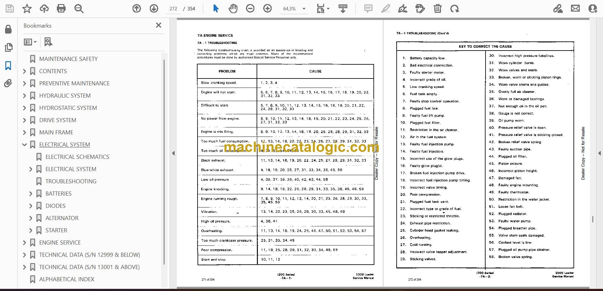
      • TROUBLESHOOTING
      • CHECKS AND ADJUSTMENTS
        • Oil Pressure
        • Valve Clearance
        • Engine Compression
        • Servicing The Air Cleaner
        • Throttle Linkage Adjustment
      • FUEL SYSTEM AND TIMING
      • FUEL FILTERS
        • Replacing The Final Fuel Filter Element
        • Cleaning The Water Filter Trap
      • REMOVING AIR FROM THE FUEL SYSTEM
      • FUEL LIFT PUMP
        • Checking The Lift Pump
        • Removing The Lift Pump
        • Installing The Lift Pump
      • FUEL INJECTION PUMP
        • Removing The Fuel Injection Pump
        • Installing The Fuel Injection Pump
        • Timing The Fuel Injection Pump (Using Dial Indicator)
        • Timing The Fuel Injection Pump (Using The Timing Tool)
        • Checking The Timing Mark On The Flange Injection Pump
      • FUEL INJECTOR NOZZLES
        • Removing Fuel Injector Nozzles
        • Checking Fuel Injector Nozzles
        • Installing Fuel Injector Nozzles
      • ENGINE
        • Removing The Engine
        • Installing The Engine
      • BLOWER HOUSING SHIELD
        • Removing The Blower Housing Shield
        • Installing The Blower Housing Shield
      • RADIATOR AND OIL COOLER ASSEMBLY
        • Cleaning Radiator And Oil Cooler Assembly
        • Removing Radiator And Oil Cooler Assembly
        • Installing Radiator And Oil Cooler Assembly
      • ENGINE BLOWER HOUSING
        • Installing The Engine Blower Housing
      • SPARK ARRESTOR MUFFLER
        • Cleaning The Muffler
        • Removing The Muffler
        • Installing The Muffler
      • CYLINDER HEAD
        • Removing The Cylinder Head
        • Removing Valves
        • Reconditioning The Valves And Valve SEATS
        • Installing Valve Guides
        • Checking Valve Springs
        • Combustion Chamber Inserts
        • Aligning Cylinder Head Surfaces
        • Installing Valves
        • Disassembling The Rocker Arms
        • Checking The Rocker Arms
        • Assembling The Rocker Arms
        • Installing The Cylinder Head
      • RECONDITIONING THE ENGINE
      • PISTONS AND CONNECTING RODS
        • Removing Pistons
        • Disassembling Pistons
        • Inspecting The Pistons
        • Installing Pistons To Connecting Rod
        • Installing Piston Assembly In The Engine Block
        • Installing New Pistons
      • CYLINDER LINERS
        • Checking Liners
        • Installing Liners
      • MAIN BEARINGS
        • Removing The Main Bearings
        • Installing The Main Bearings
        • Crankshaft End Play
      • CRANKSHAFT
        • Removing The Crankshaft
        • Checking The Crankshaft
        • Installing The Crankshaft
      • REAR MAIN BEARING OIL SEAL
        • Installing The Oil Seal
      • TIMING CASE AND GEARS
        • Removing The Timing Case Cover
        • Installing The Timing Case Cover
        • Removing The Front Seal
        • Installing The Front Seal
        • Removing The Idler Gear and Hub
        • Inspecting The Idler Gear And Hub
        • Installing The Idler Gear And Hub
        • Removing The Camshaft Gear
        • Installing The Camshaft Gear
        • Removing The Fuel Injection Pump
        • Installing The Fuel Injection Pump
        • Removing The Crankshaft Gear
        • Removing The Timing Case
        • Installing The Timing Case
        • Removing Camshaft And Tappets
        • Inspecting Camshaft And Tappets
        • Installing Camshaft And Tappets
      • LUBRICATION SYSTEM
        • Description Of The Lubrication System
        • Checking Engine Oil
        • Replacing Engine Oil And Filter
      • OIL PAN
        • Removing The Oil Pan
        • Installing The Oil Pan
      • OIL PUMP
        • Removing The Oil Pump
        • Disassembling The Oil Pump
        • Checking The Oil Pump
        • Assembling The Oil Pump
        • Installing The Oil Pump
      • OIL FILTER
        • Removing The Oil Filter
        • Disassembling The Oil Filter
      • COOLING SYSTEM
        • Belt For The Alternator And Water Pump
        • Coolant Level
        • Removing Coolant From The Cooling System
      • WATER PUMP
        • Removing The Water Pump
        • Disassembling The Water Pump
        • Checking The Water Pump
        • Assembling The Water Pump
        • Installing The Water Pump
      • THERMOSTAT
        • Removing The Thermostat
        • Checking The Thermostat
        • Installing The Thermostat
      • FLYWHEEL
        • Removing The Flywheel
        • Replacing The Flywheel Ring Gear
        • Installing The Flywheel
    • ENGINE SERVICE (S/N 13001 & ABOVE)
      • TROUBLSHOOTING
      • CHECKS AND ADJUSTMENTS
        • Serial Number
        • Oil Pressure
        • Valve Clearance
        • Check Engine Compression
      • FUEL SYSTEM AND TIMING
        • Fuel Filter
        • Removing Air From The Fuel System
        • Fuel Injection Pump
        • Removing The Fuel Injection Pump
        • Installing The Fuel Injection Pump
        • Timing The Fuel Injection Pump
        • Fuel Injector Nozzles
        • Removing The Fuel Injector Nozzles
        • Checking The Fuel Injector Nozzles
        • Installing The Fuel Injector Nozzles
        • High Pressure Fuel Lines
        • Glow Plugs
      • ENGINE AND ATTACHING PARTS
        • Removing The Engine
        • Installing The Engine
        • Blower Housing Shield
          • Removal
          • Installation
        • Engine Coolant Radiator
          • Removal
          • Installation
        • Engine Blower Housing
          • Removal
          • Installation
        • Engine Muffler
          • Removal
          • Installation
        • Oil Cooler
          • Removing The Oil Cooler
          • Installing The Oil cooler
      • CYLINDER HEAD
        • Removing The Cylinder Head
        • Removal Of The Valves
        • Reconditioning The Valves And Valve Seats
        • Installing The Valve Guides
        • Checking Valve Springs
        • Combustion Chamber Inserts
        • Cylinder Head Inspection
        • Installation Of The Valves
        • Reconditioning The Rocker Arms
          • Disassembly
          • Checking
          • Assembly
        • Installing The Cylinder Head
      • RECONDITIONING THE ENGINE
        • Pistons And Connecting Rods
          • Removal
          • Disassembly
          • Inspection
        • Installation Of Piston To Connecting Rod
        • Installation Of Rings On The Piston
        • Installing Piston Assembly In The Engine Block
        • Cylinder Liners
          • Checking
          • Installation
        • Main Bearings
          • Removal
          • Installation
        • Crankshaft End Play
        • Crankshaft
          • Removal
          • Checking
          • Installation
        • Rear Main Bearing Oil Seal
      • TIMING CASE AND GEARS
        • Timing Case Cover
          • Removal
          • Installation
        • Front Seal
          • Removal
          • Installation
        • Idler Gear And Hub
          • Removal
          • Inspection
          • Installation
        • Camshaft Gear
          • Removal
          • Installation
        • Fuel Injection Pump Gear
          • Removal
          • Installation
        • Crankshaft Gear
        • Timing Case
          • Removal
          • Installation
        • Camshaft And Tappets
          • Removal
          • Inspection
          • Installation
      • LUBRICATION SYSTEM
        • Description Of The Lubrication System
        • Oil Pan
          • Removal
          • Installation
        • Oil Pump
          • Removal
          • Disassembly
          • Checking
          • Assembly
          • Installation
        • Oil Filter And Adapter Housing
        • Removal
        • Installation
      • COOLING SYSTEM
        • Alternator And Water Pump Belt
        • Water Pump
          • Removal
          • Installation
        • Thermostat
          • Removal
          • Testing The Thermostat
          • Installation
      • FLYWHEEL
        • Removal Of The Flywheel
        • Replacement Of The Flywheel Ring Gear
        • Installation Of The Flywheel
  • TECHNICAL DATA (S/N 12999 & BELOW)
    • LOADER SPECIFICATIONS
      • Specifications
      • Engine
      • Loader Hydraulics
      • Electrical
      • Drive System
      • Capacities
      • Tires
    • ENGINE SPECIFICATIONS
      • Cylinder Head Dimensions
      • pistons And Connecting Rod Dimensions
      • Cylinder Block And Liners Dimensions
      • Crankshaft And Main Bearings Dimesions
      • Timing Cse, Camshaft And Drive Dimensions
      • Oil Pump Dimensions
      • Cooling System And Water Pump Dimensions
      • Fuel System Specifications
      • De-Rating For Altitude
      • Engine Bolt Torque
      • Grinding Specifications For Crankshaft
      • Crankshaft Regrinding Data
    • HYDRAULIC SYSTEM
    • HYDROSTATIC SYSTEM
    • DECIMAL AND MILLIMETER EQUIVALENTS
    • U.S. TO METRIC CONVERSION
    • STANDARD TORQUE SPECIFICATIONS FOR BOLTS
  • TECHNICAL DATA (S/N 13001 & ABOVE)
    • LOADER SPECIFICATIONS
      • Specifications
      • Engine
      • Loader Hydraulics
      • Electrical
      • Drive System
      • Capacities
      • Tires
    • ENGINE SPECIFICATIONS
      • Cylinder Head Dimensions
      • Pistons And Connecting Rod Dimensions
      • Cylinder Block And Liner Dimensions
      • Crankshaft And Main Bearing Dimensions
      • Timing Case, Camshaft And Drive Dimensions
      • Oil Pump Dimensions
      • Cooling System And Water Pump Dimensions
      • Fuel System Specifications
      • De-Rating For Altitude
      • Engine Torque
      • Grinding Specifications For Crankshaft
      • Crankshaft Regrind Data
  • ALPHABETICAL INDEX
  • SERVICE MANUAL REVISIONS
    • 2000-1
    • 2000-2
    • 2000-3
    • 2000-4

Bobcat Software

Bobcat PDF Manuals

Related Manuals

0
    0
    Your Cart
    Your cart is emptyReturn to Shop