Format: PDF (Printable Document)
File Language: English
File Pages: 862
File Size: 59.24 MB (Speed Download Link)
Brand: BT
Model: 8FBRE14 ,8FBRE16, 8FBRE18, 8FBRE20, 8FBRE25
Part No: 7510400-040
Type of Document: Repair Manual
$ 40
1 – Table of contents
2 – General introduction
2.1 How to use this manual
2.2 Warning symbols
2.3 Pictograms
3 – General safety rules
3.1 Work safety
3.2 Electrical system
3.3 Safe lifting
4 – Descriptions of functions
4.1 Chassis 0000
4.2 Motors 1000
4.3 Drive gear – 2000
4.4 Brake system 3100
4.5 Steering system 4000
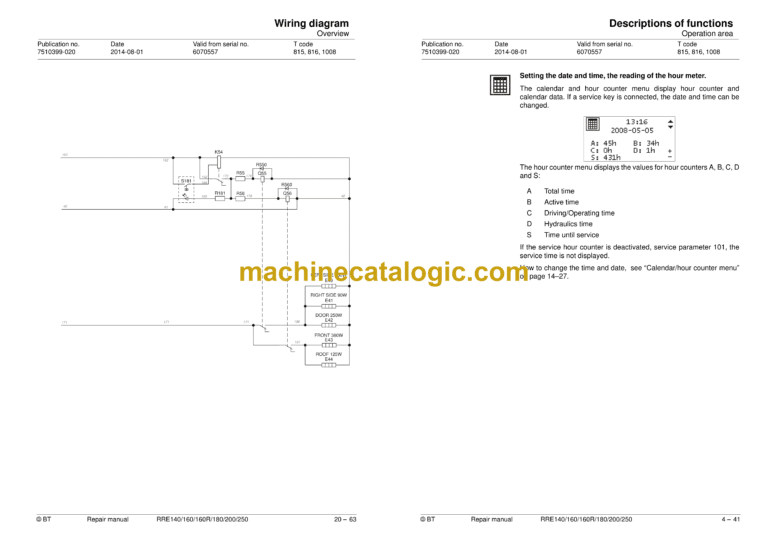
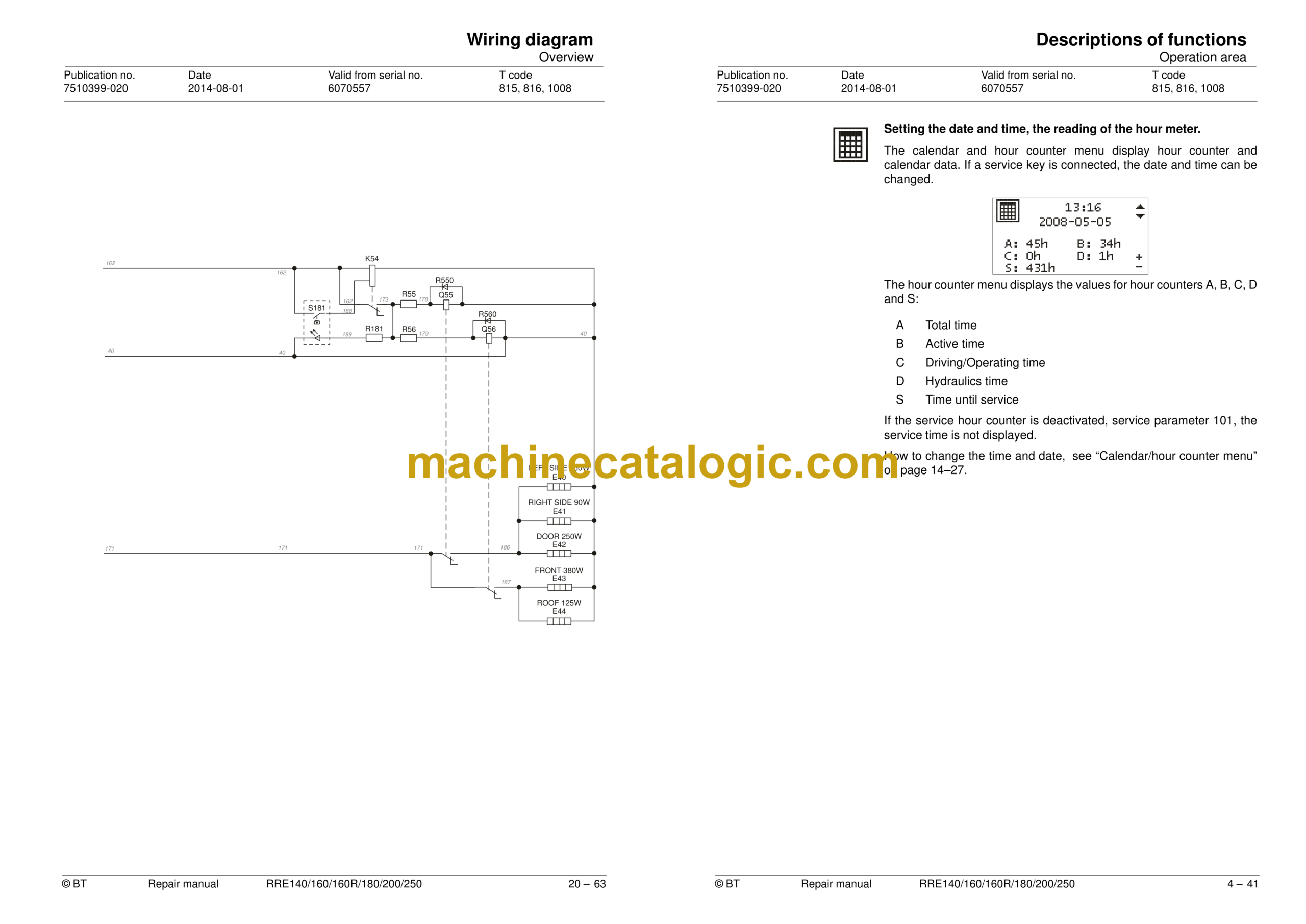
4.6 Operation area
4.7 sensors and sensors (5800)
4.8 Operation and connection sequences
4.9 Functions
4.10 Height preselector, description of function
4.11 Hydraulic system 6000
4.12 Mast 7000
4.13 Lifting devices
4.14 Accessories 9000
5 – Parameters
5.1 General
5.2 Displaying/changing parameters
5.3 Operator parameters
5.4 General service parameters
5.5 Service parameters, travel functions
5.6 Service parameters, hydraulics
5.7 Service parameters, CID
5.8 General factory parameters
5.9 Factory parameters, activation of options
5.10 Factory parameters, calibration
6 – Installation
6.1 Transporting the truck
6.2 Transporting the mast
6.3 Transporting the truck
6.4 Commissioning
7 – Maintenance
7.1 Introduction, maintenance
7.2 Safety precautions for maintenance work
7.3 Maintenance instructions
7.4 Checks for cracks
7.5 Periodic maintenance
7.6 Maintenance instructions
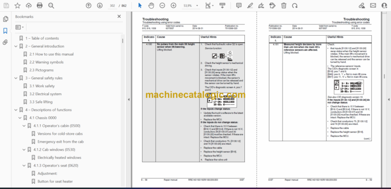
8 – Troubleshooting
8.1 Abbreviations used in this section
8.2 Truck help functions
8.3 Initial troubleshooting
8.4 Troubleshooting using blocking symbol
8.5 Troubleshooting using error codes
8.6 Troubleshooting without indications
9 – Frame/Chassis 0000
9.1 General
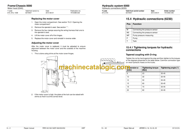
9.2 Motor hood (0340)
9.3 Battery compartment components (0390)
9.4 Operator’s cabin (0500)
9.7 Operator’s compartment (0600)
9.8 Operator controls (mechanical) C0640
9.9 Overhead guard/roof C0810
9.10 Finger/foot guards C0820
9.11 Operator protection C0840
9.12 Safety equipment (0800)
10 – Motors 1000
10.1 Motor sensors
10.2 Pump motor (1710)
10.3 Steering motor and steering unit (1730)
10.4 Fan motor/fan (1740)
10.5 Drive motor (1760)
11 – Drive gear 2000
11.1 General
11.2 Repair- and serviceability
11.3 Measures
12 – Brake and wheel 3000
12.1 Travel brake system (3100)
12.2 Single disk brake support arm
12.3 Parking brake (3300)
12.4 Drive wheel (3530)
12.5 Wheel studs (3530)
12.6 Support arm wheel (3550)
13 – Steering system 4000
13.1 Electric steering wheel (4310)
13.2 Steering reference sensor (4350)
13.3 Steering bearings (4380)
14 – Electrical system 5000
14.1 Battery (5110)
14.2 LID (5200)
14.3 Replacing pedals (5300)
14.4 Control console (5510)
14.5 Magnetic sensor (5850)
14.6 Parameter settings
14.7 PIN menu
14.8 Calibrations
14.9 Replacing the wiring harness
14.10 main computer unit MCU (A5)
15 – Hydraulic system 6000
15.1 Hydraulic hygiene
15.2 Hydraulic unit (6100)
15.3 Main valve (6210)
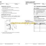
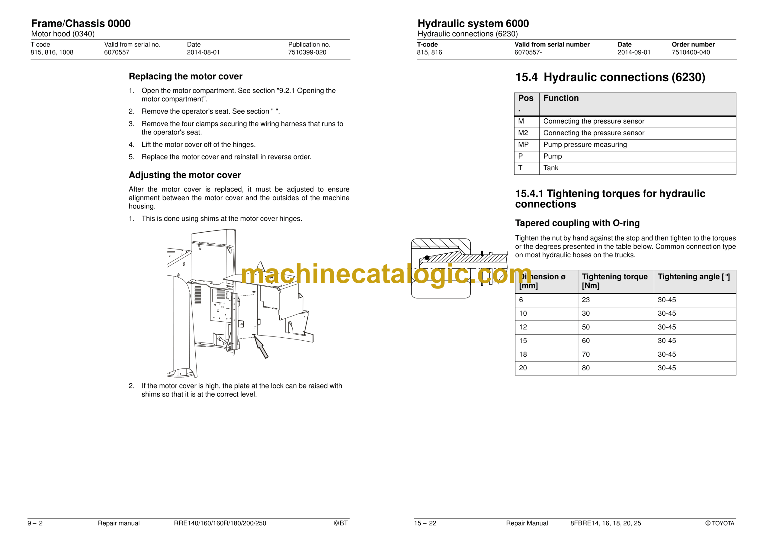
15.4 Hydraulic connections (6230)
15.5 Hydraulic system, mast (6300)
15.6 Main lift cylinder 6610
15.7 Free lift cylinder (6620)
15.8 Reach cylinder (6650)
15.9 Fork tilt cylinder (6660)
15.10 Cab tilt cylinder (6660)
15.11 Sideshift cylinder (6670)
16 – Mast/Lift system 7000
16.1 General
16.2 Checking the chain
16.3 Lubricating the chain
16.4 Adjustment
16.5 Main mast 1.6-2.5 t (7100)
16.6 Main lift chain system (7120)
16.7 Reach carriage (7190)
16.8 Lifting devices (7400)
16.9 Fork carriage
16.10 Fork spread unit
16.11 Fork extensions with adjustable fork length
16.12 Manual telescopic forks
16.13 Hydraulic telescopic forks
17 – Peripherals – 8000
17.1 Introduction
18 – Optional equipment – 9000
18.1 Introduction
19 – Appendix “Destruction instructions”
19.1 General
19.2 Marking of plastics
19.3 Pressure vessels
19.4 Sorting categories
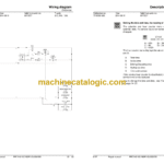
20 – Wiring diagram
20.1 Components
20.2 Component location
Figure 7 (Reach carriage wiring harness)
Figure 8 (Level/position meter)
Figure 9 (seat)
Figure 10 (DC/DC)
Figure 11 (Driver position wiring harness)
Figure 12 (Extra hydraulic function(s))
Figure 13 (Travel alarm)
Figure 14 (Roof wiring harness)
Figure 15 (Roof)
Figure 16 (Sound system)
Figure 17 (Forks camera)
Figure 18 (Battery harness)
Figure 19 (Fuse box)
Figure 20 (LID)
Figure 21 (Mast wiring harness)
Figure 22 (Fork carriage wiring harness)
Figure 23 (Reach carriage wiring harness options)
Figure 24 (Working light wiring harness)
Figure 25 (Extra outlet DC)
Figure 26 (T.W.I.S.)
Figure 27 (Shock Switch / Impact Manager)
Figure 28 (Heated windows CC)
Figure 29 (Cabling driver position CC)
Figure 30 (Heater CC)
Figure 31 (Cab heater wiring harness CC)
Figure 32 (Safety switch for door CC)
Figure 33 (Cab tilt wiring harness)
Figure 34 (Control panel)
Figure 35 (Control panel)
Figure 36 (Steering arm)
Figure 37 (MCU)
Figure 38 (Control motor)
Figure 39 (Main valve block)
Figure 40 (Li-ion wiring harness)
20.3 Cable connections and terminal posts
20.4 Fuse box A9
20.5 Overview
20.6 Details up to and including serial no. 6206800
20.7 Detailed diagram cold-store cab
21 – Hydraulics schematics
21.1 Main valve unit
21.2 Hydraulic diagrams
22 – Tools
22.1 AMP connectors
22.2 MQS connectors
22.3 CPC contacts
22.4 Other tools
23 – Appendix “Service data and grease specifications”
23.1 General tightening torques
23.2 Lubricants specification
24 – Technical data
Mast, maximum weight and maximum height