Format: PDF (Printable Document)
File Language: English
File Pages: 756
File Size: 51.78 MB (Speed Download Link)
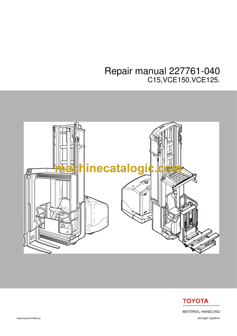
Brand: BT
Model: C15,VCE150,VCE125
Part No: 227761-040
Type of Document: Repair Manual
$ 40
1. Table of content
2. General introduction
2.1 How to use this manual
2.2 Warning symbols
2.3 Pictograms
3. General safety rules
3.1 Work safety
3.2 Electrical systems
3.3 Safe lifting
3.4 Truck modifications
4. Truck installation
4.1 General
4.2 Tool list
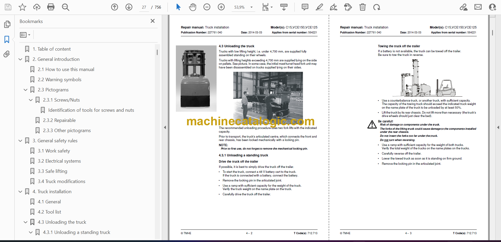
4.3 Unloading the truck
4.4 Preparations for commissioning
4.5 Installation in narrow aisle
5. Preparations for transport
5.1 General
5.2 Tool list
5.3 Dismantling the truck
5.4 Laying down the truck
5.5 Loading the truck
6. P2 (T code 712) – C15, VCE150
6.1 Preventive maintenance – Maintenance schedule
6.2 Correct inspection procedure
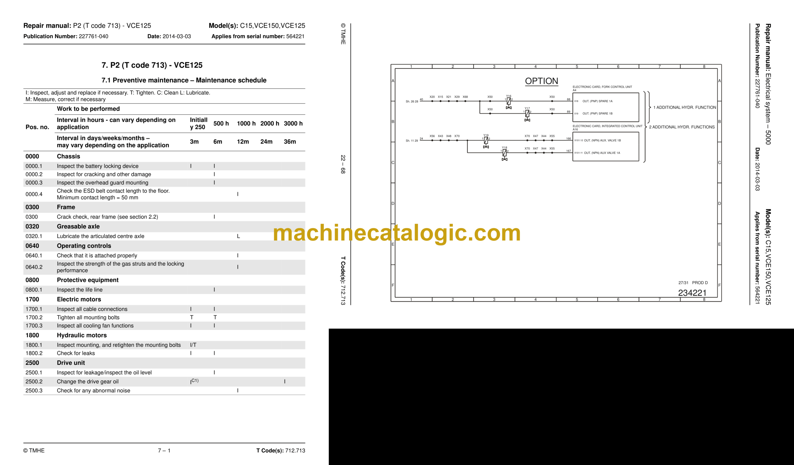
7. P2 (T code 713) – VCE125
7.1 Preventive maintenance – Maintenance schedule
7.2 Correct inspection procedure
8. P3 (T code 712) – C15, VCE150
8.1 Oil and grease specifications
9. P3 (T code 713) – VCE125
9.1 Oil and grease specification –
10. Tools – P4
10.1 Super Seal contact
11. Frame pivot – 0320
11.1 Removal/reassembly of rear chassis, including bearings
11.2 Replacing the bearing frame links
12. General tightening torque – 0400
12.1 Galvanised, non-oiled bolts
12.2 Untreated, lubricated bolts
12.3 Tightening torques
13. Electric AC pump motor – 1710.1
13.1 General
13.2 Disassembled pump motor
13.3 Disassembly and assembly of the pump motor
13.4 Replacing the ball bearing
13.5 Assembly instruction for the external temperature sensor
14. Electric DC pump motor – 1710.2
14.1 General
14.2 Disassembled pump motor
14.3 Disassembly and assembly of the pump motor
14.4 Replacing the ball bearing
15. Electric drive motor – 1760
15.1 General
15.2 Disassembled drive motor
15.3 Disassembly and assembly of the drive motor
15.4 Replacing the ball bearing
15.5 Assembly instruction for the external temperature sensor
16. Drive unit/gear – 2550
16.1 General
16.2 Components/data of the drive unit and gear
16.3 Replacing the drive motor/drive gear
16.4 Oil level check/replacement
16.5 Repairs
17. Brake system – 3100
17.1 General
17.2 Description of functions
17.3 Electro-mechanical disc brake, drive motor
17.4 Replacing the brake unit and dismantling the brake unit to replace the friction disc
17.5 Disc brake with multiple discs, support arms
18. Wheels – 3500
18.1 Drive wheels – 3530
18.2 Support arm wheels – 3550
19. Steering system – 4000
19.1 General
19.2 Function description
19.3 Troubleshooting
20. Steering cylinder – 4160
20.1 Instructions for checking for internal leaks
20.2 Recommended procedure
20.3 Remedial actions
20.4 Removing a steering cylinder from the truck
20.5 Fitting a steering cylinder on the truck
20.6 Repairs to the front steering cylinder mount
21. Wire guidance system – 4500
21.1 Wire guidance
21.2 Wire guidance components
21.3 General description of the function
21.4 “Best practice” for adjusting the wire guidance.
21.5 Parameters
21.6 Warning and error codes
22. Electrical system – 5000
22.1 General
22.2 Main Computer Unit, MCU (A5)
22.3 Fork computer unit, FCU (A4)
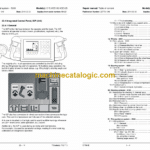
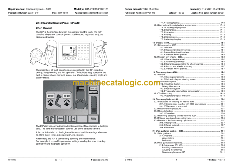
22.4 Integrated Control Panel, ICP (A16)
22.5 AC regulators, ACTL (A1), ACTR (A31) and ACH (A2)
22.6 DC regulator, DCHI (A32)
22.7 Parameters
22.8 Diagnostics and troubleshooting
22.9 Hand-held terminal 1307
22.10 Electric system, overview
22.11 Symbol list and electric wiring diagram
22.12 Component List
22.13 Component location
22.14 Functional description, General
22.15 Functional description, starting, driving, steering and braking
22.16 Electrical description of the hydraulic functions
22.17 Turret head unit (T code 712)
22.18 Shuttle fork unit (T code 713)
22.19 Display
23. Parameters – 5700
23.1 General
23.2 Accessing parameters
23.3 Truck parameters
24. Calibration – 5700
24.1 General
24.2 Calibration of the ICP controls – “CONTROLS”
24.3 Calibration of steering – “STEERING”
24.4 Calibration of wire guidance – “WIRE”
24.5 Calibration of the turret head fork unit functions – “FORKS” (T code 712)
24.6 Calibration of Shuttle fork (T code 713)
24.7 Calibration of weight indication – “WEIGHT”
24.8 Calibration of B cylinder pressure – “PRESSURE”
24.9 Learn status codes – FCU
25. Error codes – 5700
25.1 General
25.2 Warning and error codes
25.3 Warning and error codes, description
25.4 Extra logging functions
26. Hydraulic system – 6000
26.1 General
26.2 Hydraulic cleanliness
26.3 Symbols
26.4 Cabin lifting
26.5 Fork units and steering
26.6 Extra hydraulic function (T code 712)
26.7 Operations/repair
27. Hydraulic tank – 6110
27.1 Replace the hydraulic oil
27.2 Replacing the tank
27.3 Installing a new tank
28. Hydraulic pump – 6140
28.1 General
28.2 Bleeding the hydraulic pump
28.3 Replacing the hydraulic pump for main lift (A1, A2)
28.4 Replacing the hydraulic pump for steering and fork hydraulics (B)
28.5 Troubleshooting internal leakage in the hydraulic pump for steering and fork hydraulics (B)
29. Accumulators – 6280
29.1 Charging of the lifting and steering accumulators
29.2 Measuring the pressure in the steering accumulator
30. Main lift cylinder – 6610
30.1 Replacing the seal in the B cylinder
31. Main mast and mast – 7100
31.1 Setting the cab and mast stoppers
32. Main lift chain system – 7120
32.1 General
32.2 Checking the chain setting
32.3 Checking the chain
32.4 Cleaning
32.5 Lubrication
32.6 Adjusting chains
33. Initial mast/Turret head fork unit – 7200
33.1 General description
33.2 Assembly/disassembly of the initial mast
33.3 Inspection and replacement of belts used for fork traversing
33.4 Friction plate adjustment
33.5 Parallel adjustment of forks
34. Shuttle fork – 7800
34.1 Assembly of the shuttle fork
34.2 Maintenance
34.3 Replacing the shuttle forks
34.4 Measures
35. Magnet installation in narrow aisle – 8100
35.1 General
35.2 Magnetic Sensor Switch Positions
35.3 Standard Magnet Positions – Rail and Wire Guided
35.4 Aisle indication – method of operation
35.5 Aisle End Brake
36. Wire guidance equipment – 8200
36.1 General
36.2 Generator
37. Height preselection – 9390
37.1 General
37.2 Parameters
37.3 Programming
38. Appendix A: Technical update
38.1 AC pump motor, C code 1710, main lift
38.2 AC drive motor, C code 1760
38.3 Motor controllers, C code 5460, ACTL (A1), ACTR (A31) and ACH (A2) generation 5
38.4 New pivot point/steering potentiometer for C15, VCE150A and VCE125ASF
38.5 Wiring diagram VCE150 (T code 712) from serial number 6213314
38.6 Wiring diagram VCE125ASF (T code 713) from serial number 6213314
39. Index
